This week, we learned how to make circuit boards by soldering components onto MCBs made on a desktop milling machine.
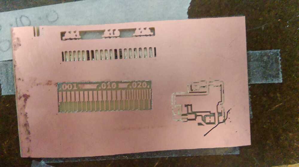
To familiarize myself with the machine, I decided to mill a spacing test pattern with the 1/64" tool. I cleaned the board and the sacrificial layer, carefully applied double sided tape, made sure I was running the correct local version of the mods server, put in the right tool and precisely set the origin. I then pressed go and watched the machine cut. End result: Something had gone very wrong!

I hadn't restarted the mods application after the previous user, and it had been left with the settings for the 1/32" cut-through pass. I had failed to notice this, so the machine had thought it was using a 1/32" bit and cutting through the board.
After a short break for a class, I came back and tried again, making sure the correct defaults were selected. This time, the test came out nearly perfectly:
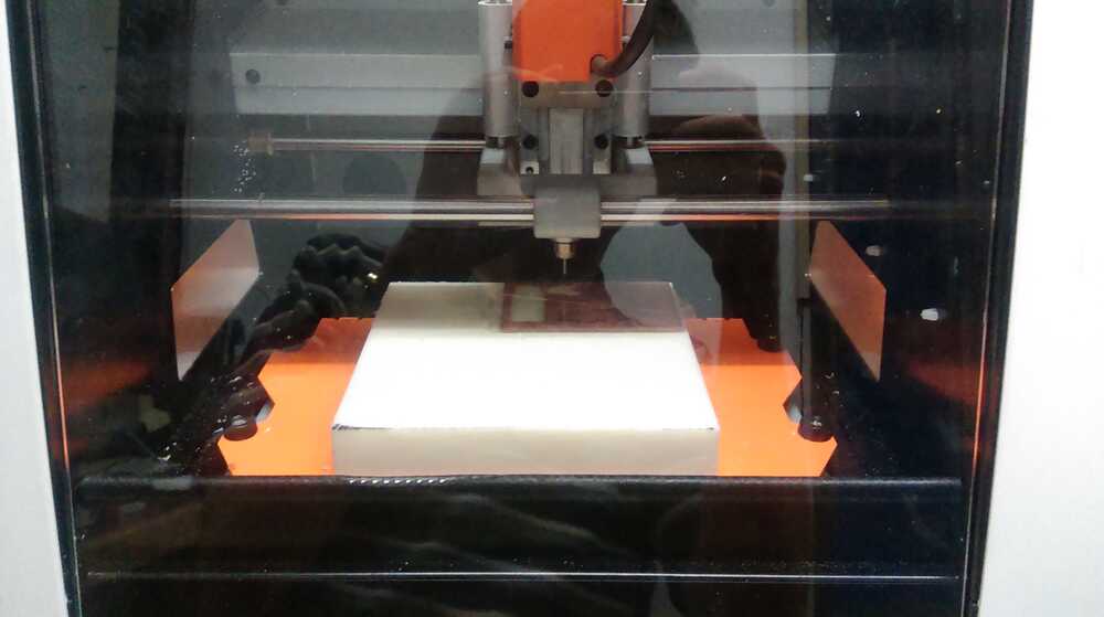
So I uploaded the traces file for Brian's FabTinyISP ATtiny45 in circuit programmer and started the machine up (again checking for the correct settings). Just to be safe, I made two boards so that I could afford to make mistakes while soldering. Here is the machine in action:
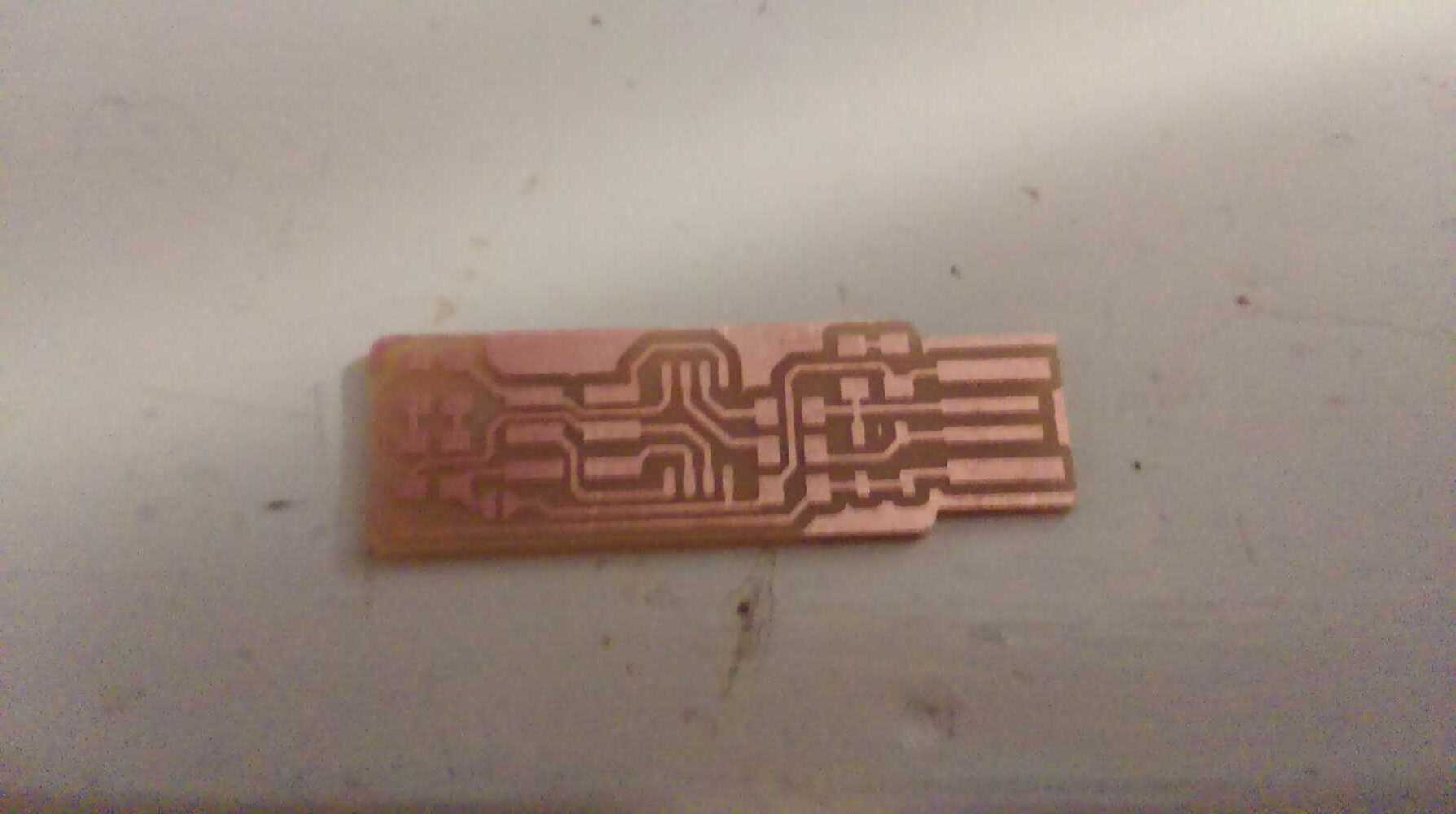
And here is the final result of the milling
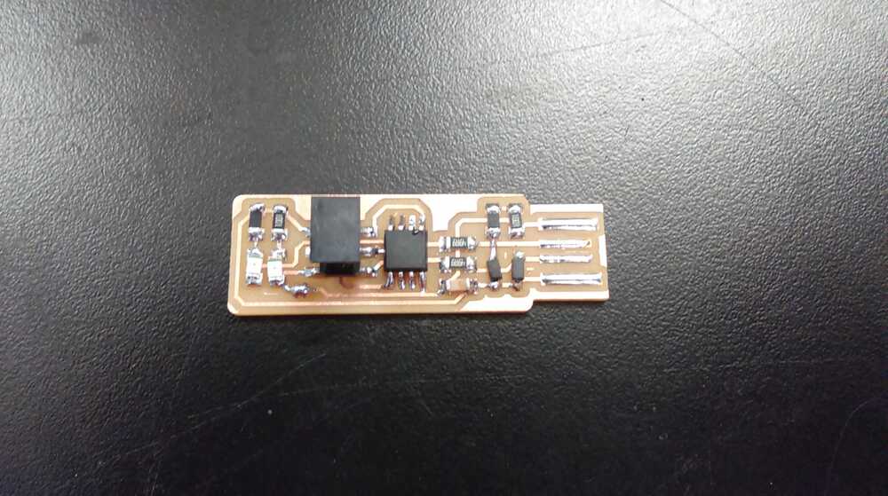
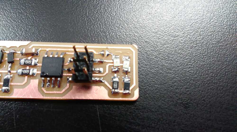
This part went pretty smoothly, and there's not much to say (or show). Somehow I did end up with two red LEDs (I think someone else must have put a strip of red LEDs in the green box). Lesson: test your LEDs before soldering them. I did improve the USB contacts with solder, and I also put three layers of adhesive vinyl (from the vinyl cutter stock) on the back to improve the USB fit. Here is the final product of the soldering stage:
This part was the most complicated, mostly since I decided to do this part on my own Windows laptop instead of using the fab shop linux computer. Don't fear though! There are very thorough instructions here.There are a lot of steps, but everything is well-explained and worked for me on the first try. You should know your Windows system fairly well if you want to try this though.
I also decided to use another FABTinyISP to program mine, which was a cool sort of recursion. There were a few working ones in the fab shop, so I grabbed one and ran the commands
The only hiccup worth mentioning came when I tried to check whether my device was working as a USB device before setting the final fuses. When I plugged it directly into my laptop, nothing showed up in my device manager, and it didn't matter which USB port I used. I went and tested it on the shop Linux machine, and it showed up nicely, and I could have been satisfied with that, but I decided to troubleshoot my system. After some Google searches, I figured out a solution, explained below
Basically, the problem is that Windows doesn't actually have its USB ports on all the time, as a power-saving measure. When you plug in a standard USB device, the device interacts with the USB port in some way that can 'wake the port up' so that the computer can start interacting with the device. Our FabTinyISP boards, however, because they are sort of hacking the USB protocol, can't wake up the USB ports properly, so the computer never turns on the USB ports.
Happily, there is a (somewhat awkward) solution to this:
Having figured that out, I finished the programming and desoldered the jumper bridge. Now I have my own programmer that is ready to program all of the other controllers I make!