This week we learned how to design circuits.
I decided to use KiCad for the design part of this week's project, as I like being comfortable with free, open-source tools so that I can continue to use them once I lose access to academic licenses. The documentation provided with KiCad was very thorough and helpful in learning to use the tools.
My plan was to make a version of the Hello_world tiny44 FTDI board that would have an extra button and LED for limited user interaction. First, I had to make a schematic showing the components and connections I wanted for my circuit. You may notice that I forgot to add a resistor in series with my LED.
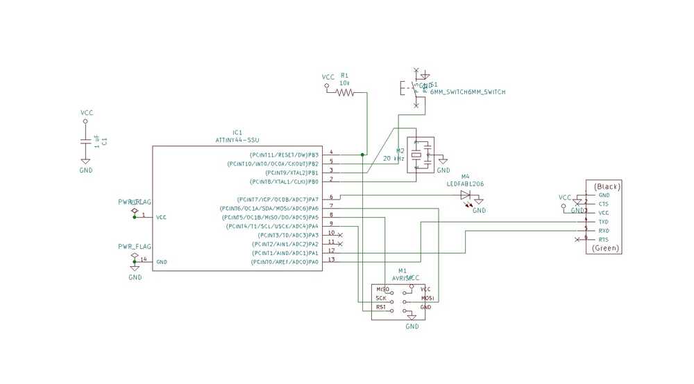
Next I had to create a netlist and assign my component footprints. I used the fab component library for my components and footprints. The KiCad library, at least seems messy, with seeming duplicates and no documentation, so next time I'll try using a Digikey or built-in library, but it worked this time.
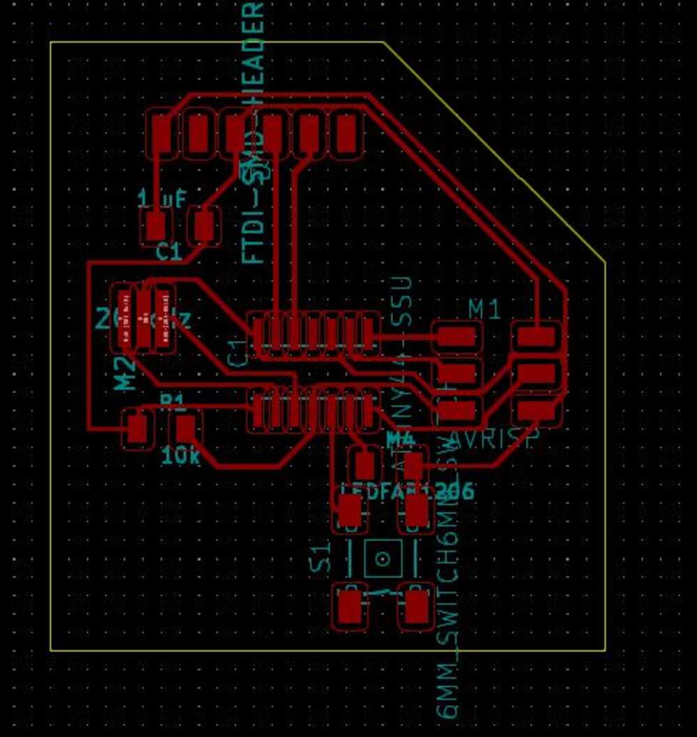
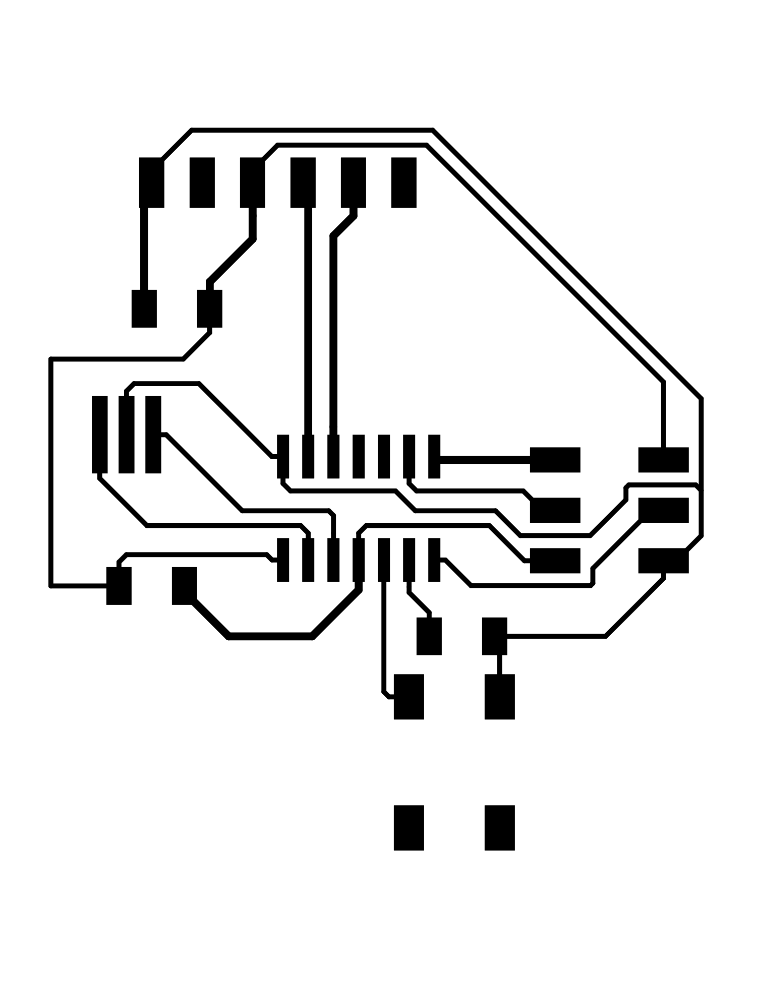
The hardest part was actually laying out the PCB. I opted to do this all manually so that I could get a feel for what goes in to trace routing. I used 0.25 mm traces, with 0.5 mm clearance (to give a bit of room beyond the minimum of 0.397 mm for our 1/64" endmill). I first routed everything without the extra button and LED and then used forward annotation from the schematic to add in these two extra components (notice anything missing still?). Here is the end result:
I then exported svg files for milling. The mods program I used to communicate with the milling machine (see week 2 for details) needed a PNG input, so I first tried converting the files using ImageMagick. My first mills, however were failures.
There were so many things wrong with the first boards that it was a bit hard to troubleshoot, but here are some things I figured out:
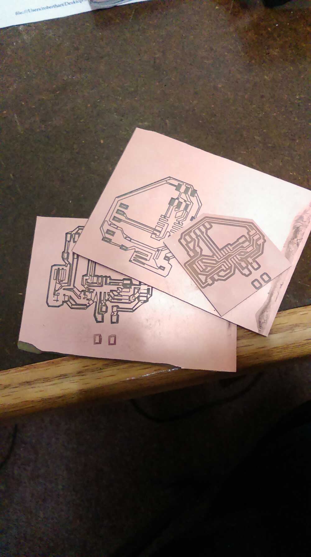
Finally, I figured out how to make my board correctly! (see the good board on top of my two bad cuts)
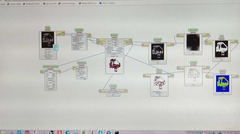
Here is a picture of the mods workflow using the low dpi PNG. Notice the strange pattern in the machine path result that doesn't really follow the input pattern.
And here are the final PNG files that I used for the correct milling run:

I then soldered the components on. It was at this point that I realized I had forgotten the current-limiting resistor for my LED. Rather than start again, I decided to try some post-production modification by cutting a trace with a razor blade and soldering the necessary resistor over the gap. This seemed not to cause any short circuits, so I went ahead with testing.
For programming the board with the Hello World program, I used the files and rough instructions provided on the embedded programming part of the course website. These were meant for a linux/mac environment using Python 2.x, while I was attempting to do the programming on Windows 10 using python 3.7, so I had to adapt the instructions moderately.
First, I saved the various code and makefiles and compiled them as the first instruction specified:
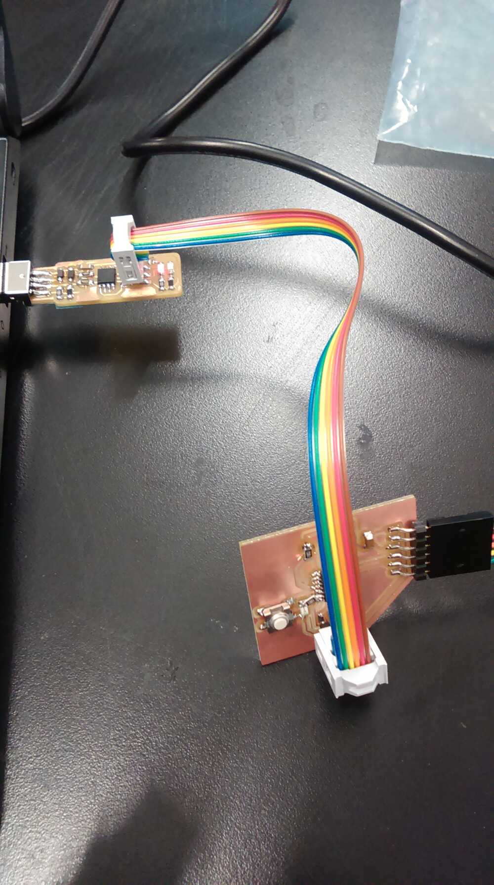
Next, I plugged my board into my computer using an FTDI to USB cable, plugged a fabTinyISP into my computer, and connected them via their ISP headers. I then programmed the board. Here, I used the described commands, but omitting the 'sudo' before the command.
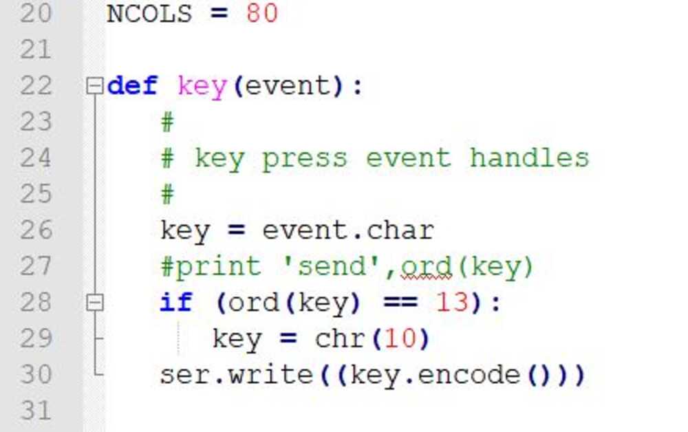
In order to run the last command to interface with my new board, I had to find and save term.py, a piece of python code written by Neil that gives you a terminal-like interface to a serial connection. This code, however, was written for a Python 2.x environment, and I wanted to run it using my Python 3.7 environment. I therefore had to make a few changes in the code:
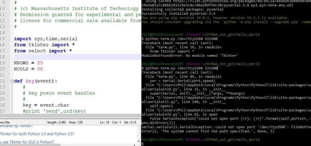
At this point, I had a working python script for the terminal, but it still wouldn't run, since I was missing the PySerial package required to interface with the serial port. I therefore used the built-in pip package installer to install this library.
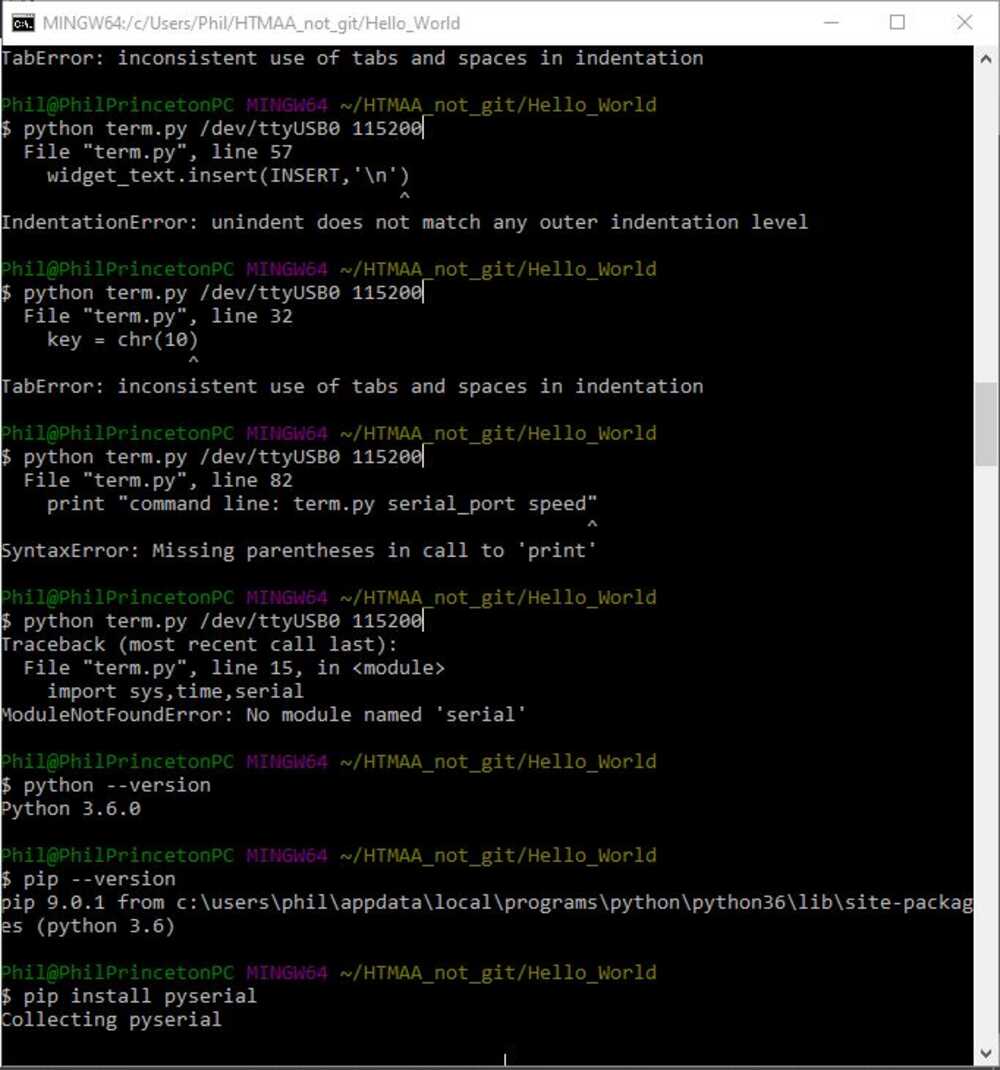
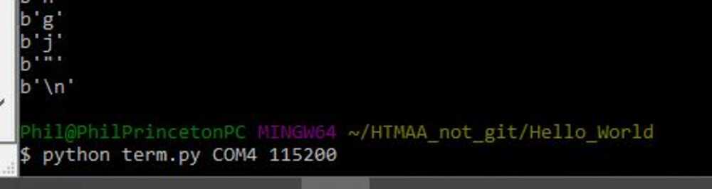
Now I was almost ready to run the terminal, but I couldn't just copy and paste the command from the linux/mac instructions because port naming is different in Windows. I therefore had to determine what port my device was plugged into. I did that as follows:
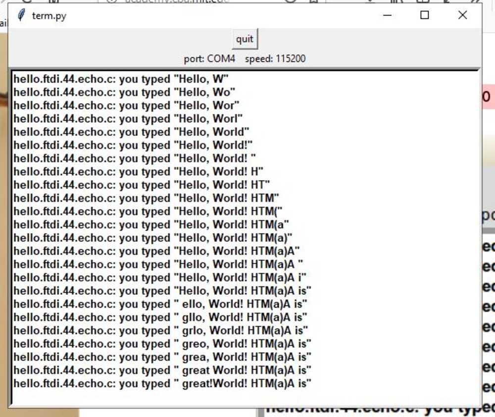
I tested how big of a memory the chip had available to store my messages by writing "Hello, World! HTM(a)A is great!" As you can see in the following image, the buffer starts overwriting itself from the beginning after 24 characters.
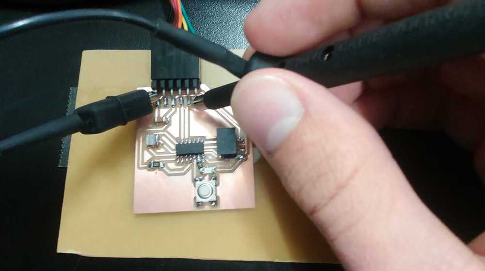
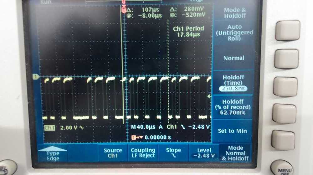
As a last step, I tried to use an oscilloscope to view the signal passing in and out of the TTY connector on the board. By turning off autoscroll on the oscilloscope, I was able to capture a view of the signal.