Week 3
Let's go home
Objective
The goal of this week was to make an in-circuit programmer.
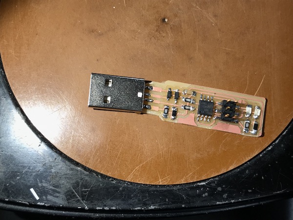
I used an ATtiny45 to build to the FabTinyStar!
PCB: Printing a Circuit Board
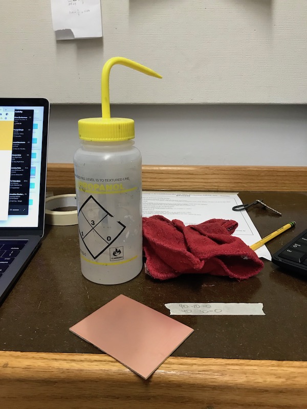
I picked up a nice piece of blank single-side circuit board, cleaned it with some isopropanol and a cloth, and also wiped down the sacrificial layer of the Roland SRM-20 mill that I'm using for printing my circuit board.
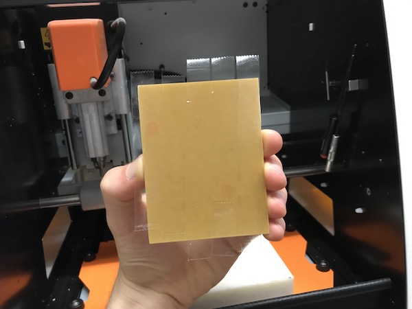
I added some double-sided tape to the back of the board (making sure that it didn't crease or overlap) and pressed it firmly down on the sacrificial layer. This is to make sure that the mill has a perfectly flat surface to work on. If it's not flat, the copper might not get removed on all parts of the board.
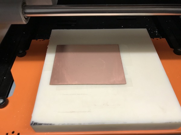
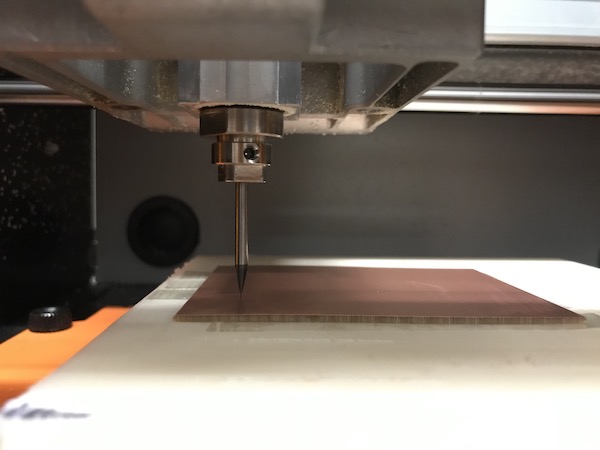
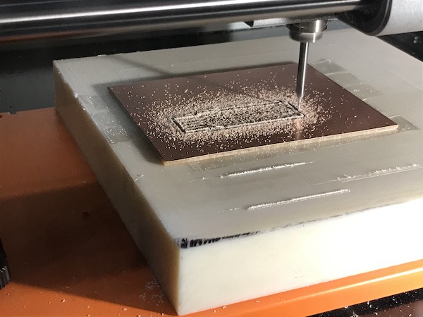
After I placed the board on the sacrifical layer, I changed the bit of the mill to the bit with 1/64" width. I then set the origin of the drill (using the local Roland SRM-20 mod) so that it would be in the lower-left corner of where I wanted my circuit to be printed. From here, I lowered the bit to the board carefully, making sure that the tip didn't fall and break. When I level the bit to the surface of the board, I tightened the screw so that the bit would stay stable.
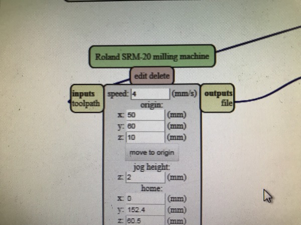
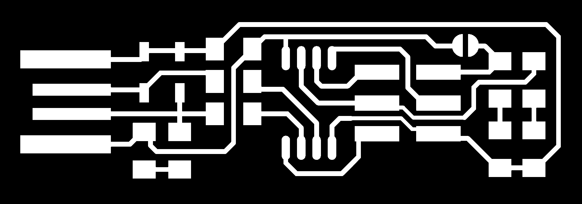
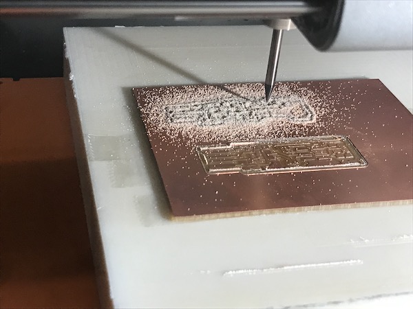
Next, I uploaded the png of the circuit design to the Roland SRM-20 mod, calculated the path for the mill, and then sent the file to the machine to mill!
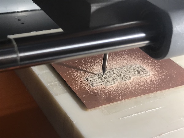
I vaccuumed the debris from the cut.
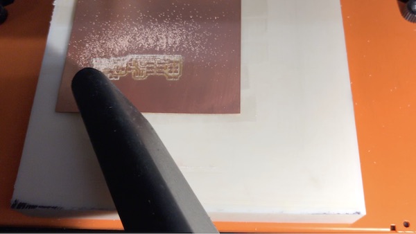
Then I changed the bit to the 1/32" width bit and repeated the same process to cut the outline (png) of the circuit board.
But this was my downfall! Because I never changed the setting on the mod to use the default cut settings for the 1/32" mill outline.
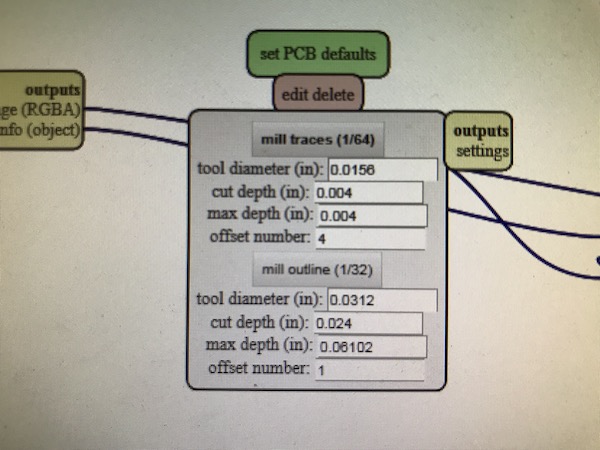
Because of this, when I removed the circuit board from the machine, the cut wasn't deep enough and it only made an outline.
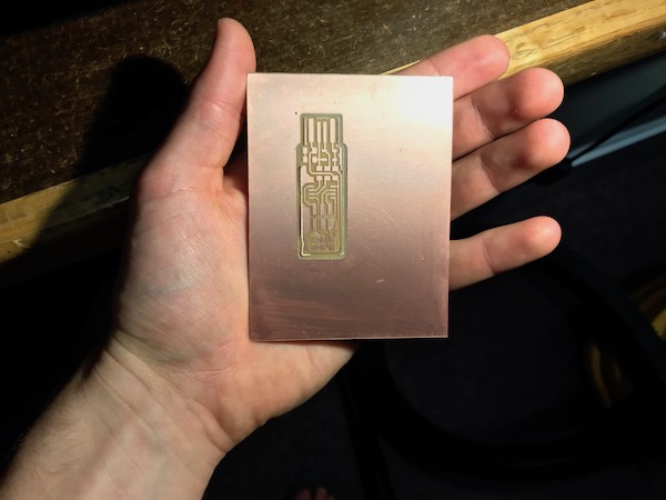
And now that I removed the board, I wasn't able to recut the outline on the same area because I wouldn't be able to align it correctly.
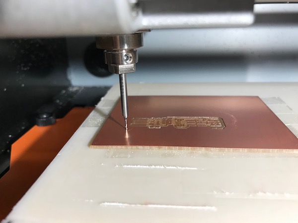
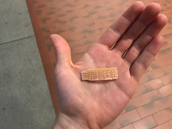
So, I redid the original 1/64" cut of the traces on a different section of the board. After this, I switched the bit and changed the setting on the mod to the 1/32" mill outline and finally got the circuit board all cut out!
Soldering
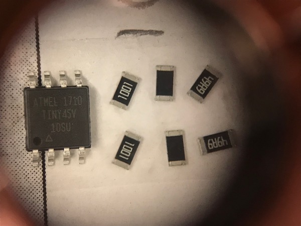
In order to build the processor, I needed all the right ingredients! Or should I say components? The components needed for the FabTinyStar are:
- 1x ATtiny45
- 2x 1kΩ resistors
- 2x 499Ω resistors
- 2x 49Ω resistors
- 2x 3.3v zener diodes
- 1x red LED
- 1x green LED
- 1x 100nF capacitor
- 1x 2x3 pin header
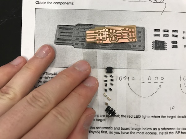
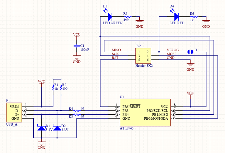
For figuring out where to place each component, I referenced the two different representations of the circuit below that Brian included on this webpage.
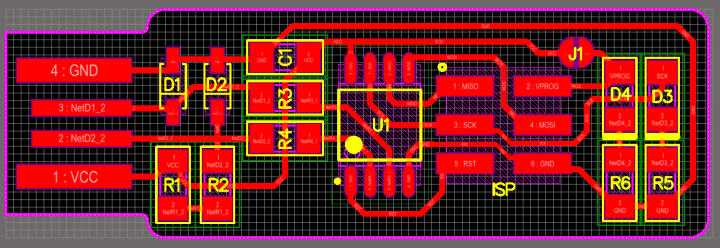
I started soldering in the middle of my circuit board by beginning with the 100nF capacitor and the two 49Ω resistors. If I started with the ATtiny45 or the 2x3 pin header, it might have been too difficult to place the other components.
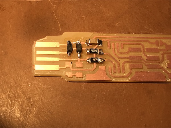
The first few components I soldered were not too beautiful. The solder cooled in sharp, bitter, angry formations.
But when I got to that 1kΩ resistor, I finally got that round, smooth, clean, shiny solder!
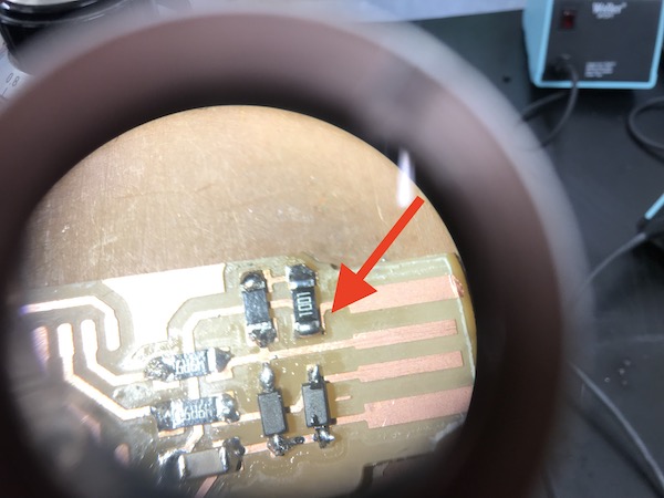
After that, I just kept soldering until I finished the whole circuit.
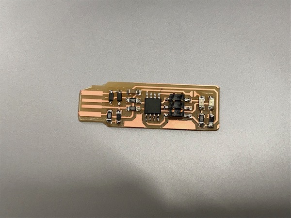
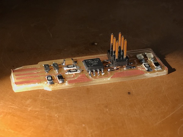
Then, I attached a USB head to the board.
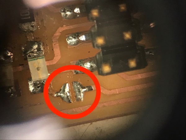
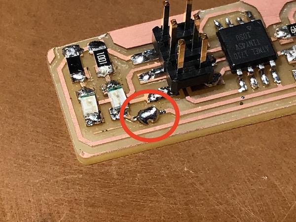
And finally, I soldered a bridge between two copper pieces on the board that weren't yet touching so that the 2x3 pin header could be used to program the ATtiny45.
Programming the Microcontroller
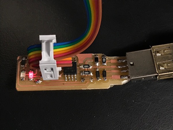
Time to start programming! I plugged the USB of my board into a USB port which was connected to a computer. The red LED lit up, which meant that power was running through the circuit. I also connected my 2x3 pin header to another 2x3 pin header on a different programmer that was already sit up. This programmer was also connected to the computer through a USB.
I downloaded the firmware (fts_firmware_bdm_v1.zip) needed to program my board.
I unzipped it, and made sure the .hex file was made that would be used to program the ATtiny45. From here, I ran make flash to program the memory of the controller with the contents of the .hex file. Then, I ran make fuses to set up all the fuses.To check that everything worked, I unplugged both my board the programmer I used to program my board. Then I plugged my board back in and typed in the command lsusb in the terminal window. It showed my programmer, "Multiple Vendors USBtiny"!
Seeing that everything was working, I used some desoldering braid to remove the solder that connected the bridge on the board. This way the ATtiny45 will not be able to receive input from the 2x3 header in the future.