david gil
Art Design and the Public Domain | 2020
Harvard Graduate School of Design
final project
Color Theory
concept
Color Theory was created during a semester long research in Art, Design and Public Domain at Harvard’s Kennedy School, Graduate School of Design, Science Center and at the Media Lab at MIT. It is intended to fill the practices of painting and film with both cosmological and social content. Instead of applying paint with a brush to a solid surface or shooting a film inspired by real life events, Color Theory is a performative interdisciplinary art project using one of the most fragile forces of the universe, gravity, as a visual representation of the gradient colors of a new form of modernity, which according to sociologist Zygmunt Bauman, is embodied by undesirable “vagabonds” or refugees, the weakest social segment in today’s world.
In a time in history where the omnipresence of screens constantly bombarding real-time highly mediatized global traumas using reality television tactics has led to a certain degree of lawful lawlessness, some sort of isolating compulsive engagement in rewarding manipulated full-color “realities” and anchored the foreigner into the sphere of collective cultural, racial and ideological fear. Forced out of his/her own public space, by chaos and war, the already traumatized refugee is pushed to the invisible boundaries of the city and forced into further social and psychological withdrawal.
Color Theory mathematically decomposes SMPTE color bars to metaphorically adjust the saturation, chrominance and luminance of today’s Liquid Modernity. It questions our perception of a screened reality where just like free-falling liquid color traces a geodessic straight line, the foreigner traces the shortest path between otherness and social stigmatization.
film
fabrication
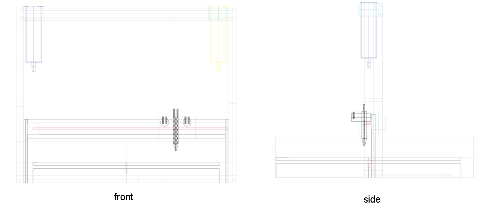
In collaboration with Tobias Putrih and Graham Yeager, I used traditional methods to fabricate a painting mechanism composed of a metallic welded frame, a steel scissor jack and a series of medical syringes. Initially, the mechanism is actuated manually, but with the help of Robert Hart, I fabricated and coded an Arduino board to electronically actuate the painting.
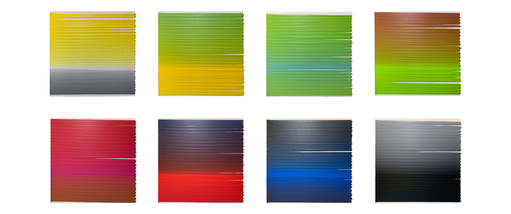
27 syringes are aligned next to each other to cover the entire width of the 18x18x1.5 inches canvas. The nozzle of each syringe measures 0.4 millimeters. 108 individual geodesic lines are needed, and the dripping process needs to be repeated four times for full coverage. The painting mechanism is anchored to the wall and the canvas is moved 0.3 millimeters after each dripping process.
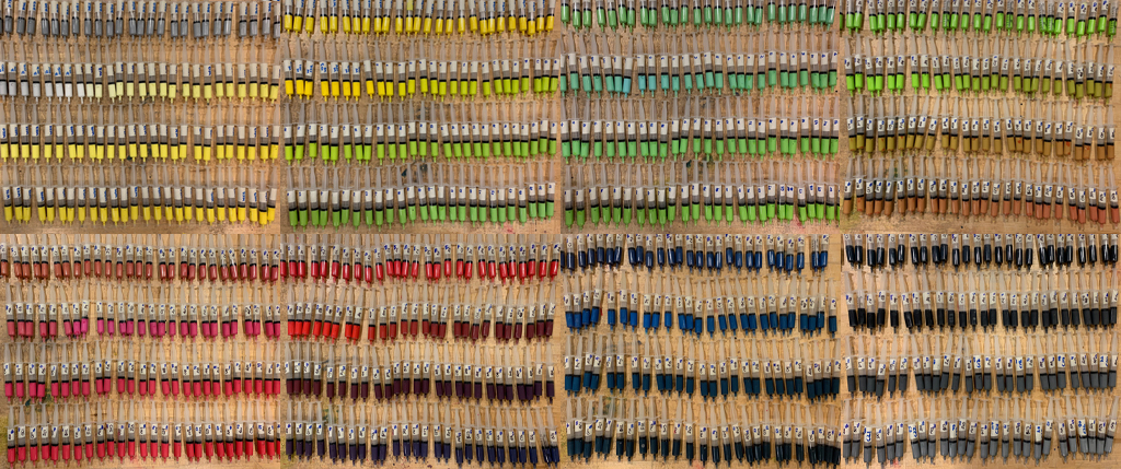
To cover the entire length of the canvas, each syringe needs to be loaded with 3.5 milliliters of liquid paint. To play it safe, 5 milliliters are used. A manual mixing process is designed to mathematically create a gradient of color going form 100% color A in the first geodesic line to 100% color B in the 108th one. With 1% waste, calculations indicate that the original mix need to be started with 300 milliliters of 100% color A. The first syringe is loaded 5 milliliters, then 3 milliliters of color B are added to the mix and manually rotated to blend color mix. The process is repeated 107 times. Since each syringe is loaded with 5 milliliters and only 3 milliliters are added, the amount of original mix gradually decreases as syringes are loaded in this continuous manual mixing process. When the 107th syringe is loaded, there is no more mix left. The 108th syringe is loaded with 100% color B.
Each syringe is labeled with a numbered 1-108 to keep track of color gradients and with a group (A,B,C,D) corresponding to a the dripping order. The canvas is primed with white paint and left to dry. Then the painting mechanism is loaded with group A. The first set of liquid paint is released followed by a 8 hour drying time. Then group C, B and D are executed until the canvas is completely covered by geodesic lines.
proposal
For How to Make Almost Anything, I would like to expand Color Theory and to digitally fabricate an enhanced version integrating rotation (the curve) and an electronically controlled mixing process.

updated proposal
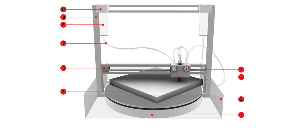
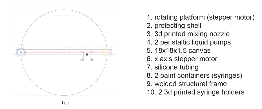
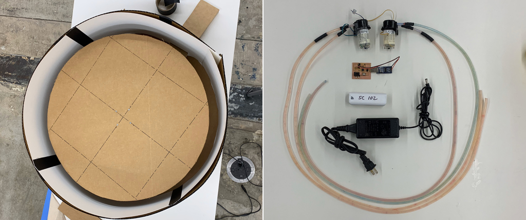
In my original draft, I imagined the painting mixing nozzle and the rotating mechanism to be integrated into one unique unit. After more thought, I realized that unifying these two mechanical actuations would be an unnecessary complex task. I observed the Prusa 3d printers available in the lab and concluded that the heating plate is completely independent of the 3-axial movement of the nozzle. I followed this example and updated the design of the project. It would be now composed of two independent mechanisms but held together by one unique structure, just like the Prusa 3d printers. The whole project now included :
1. A rotating platform actuated by a stepper motor. This platform would allow me to paint canvas measuring at least 18x18 inches.
2. A 3d printed mixing nozzle connected to two peristaltic liquid pumps mounted to a x-y axis also actuated by a stepper motor.
3. 2 suspended paint containers attached by 3d printed holders to a metal welded structural frame
4. A protecting shell that would capture spilling paint from splattering all over the place.
centrifuge painting prototype
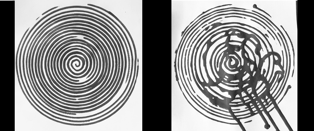
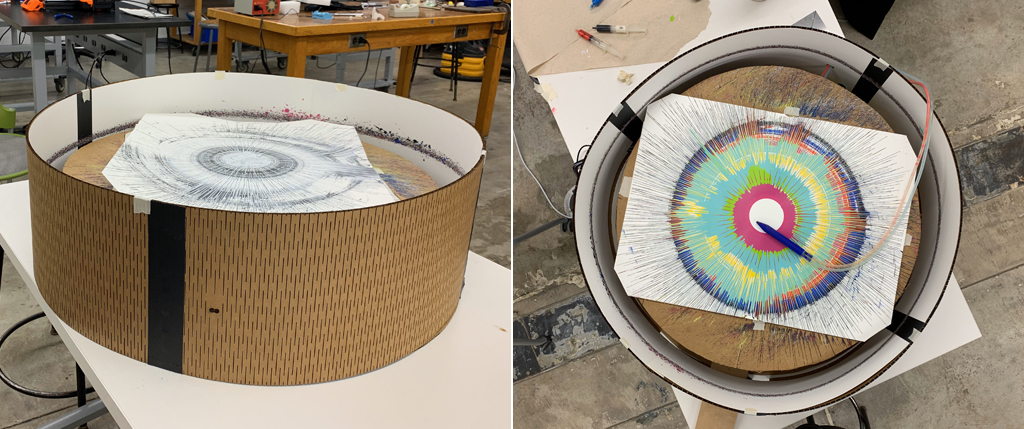
I visited Graham at CBA’s lab to share with him my updated design and to play creative ping pong as to the best approach to furthering my research. He advised me to use the pottery wheel machine available in the lab to make a centrifuge painting prototype. We used colored ink paint. The first prototype was made with the pottery wheel positioned in the horizontal plane at low speed, the result was a regular spiral drawing. We then placed the wheel in the vertical plane for a second trial and used the same speed. The result is very similar to the first, except that irregular paint drips started forming as the drawing was executed. I then asked if we could speed up the machine to the maximum limit of the pottery wheel and we made two other drawings (horizontal and vertical), which visually showed the effect of centrifugal force on liquids on the canvas. This is exactly what I was looking for and focused my ongoing research on this direction.

3d printed mixing nozzle
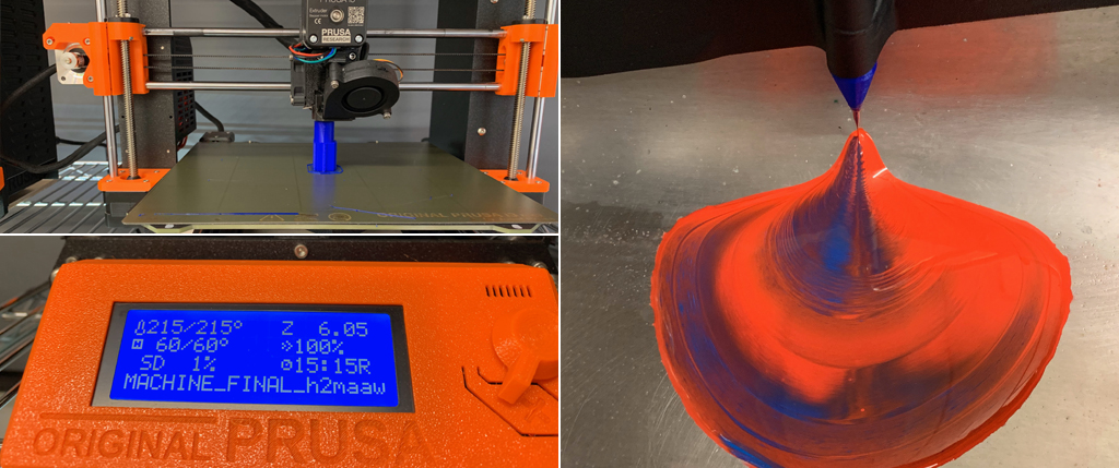
I showed Rob the prototype paintings and explained to him the new direction of the project. My objective was to create a series of centrifugal paintings and to integrate the gradients of colors I have experimented with last semester with with Tobias Putrih. To do this, he advised me to work on a nozzle design that would allow two manually injected liquids to mix. He proposed the shape to be cylindrical and that inside I created crisscrossing channels that we allow the paint to mix either by gravity or by some form of mechanical actuation (we will come back to this). I used Rhino to extrude the nozzle and to create the channels. I saved the files in STL format and then imported them into Prusa slicer to launch the 3d printing job, which took over 13 hours. After the nozzle was printed, I attached two 0.6mm soft silicone tubes and manually injected first water and then 2 different color paint. The result was not perfect, but beautiful. More research is needed on microfluids in order to perfect the mixing design.
3d printed paint containers
I also designed two paint containers that included a system to hold each of the pumps. I used rhino and exported the file into STL format to slice it, but when I opened the STL file, the base of the paint containers appeared square instead of round, as originally intended. I tried recreating the design using a different path, but every time I exported it, it gave me the same error. At the end, following some advice from my classmates, I selected the entire 3d design, exploded it, joined it and grouped it. This time, the file was successful. I used Prusa slicer and 3d printed both containers. Each file took 10 hours.

board design and programming
In parallel I followed Robs advice to look into output week in order to find a board that could help me synchronize two peristaltic liquid pumps to turn on and off at different intervals. We opted to base my board design from Neil’s speaker mosfet board and to add two 5V peristaltic pumps as well as one switch to turn the power on and off. I downloaded Neil’s sample and used illustrator and color lines to understand how the different elements were connected and listed the different components needed :
Tiny 45
2 Mosfet
5V DC peristaltic liquid pumps
Regulator 5 volts
Capacitor 1uF
Resistor 10h
2 2x2 headers
5.5mm/2.1 plug
2x3 header
switch
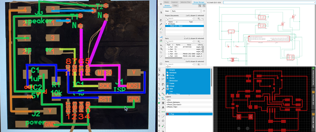
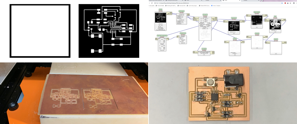
Once I understood how the components on the board were interconnected, I used Eagle to create a schematic. This process was complex and time consuming. Just understanding the name of each component in the library was a whole adventure. With a final design in hand, I went to the milling machine to take care of milling the board on a single sided coper sheet. The first couple of trials were unsuccessful because I used double sided tape to adhere the sheet to the cutting bed, but the moment the machine started milling, the double-sided taped sheet came off. This had happened a couple of times before, so I decided to add painters’ tape all around the edge of the coper sheet. This time, the milling process was carried out until the end; however, the 0.165 millpoint was defective. I had to restart the process. I then took care of soldering. We then wrote a simple extrusion Arduino file and programmed it to the board.
//Define Pin color A and B
int motorPinA = 0;
int motorPinB = 1;
int SpeedA;
int SpeedB;
void setup()
{
//Set the PWM Motor pin as an output
pinMode(motorPinA, OUTPUT);
pinMode(motorPinB, OUTPUT);
}
void loop() {
digitalWrite(motorPinA, HIGH);
digitalWrite(motorPinB, LOW);
delay(5000); //Hold it!
digitalWrite(motorPinA, LOW);
digitalWrite(motorPinB, HIGH);
delay(5000); //Hold it!
}
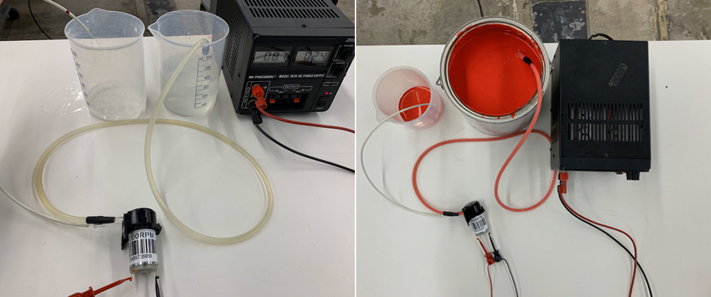
peristaltic liquid pumps and mixing
When we tried using the pumps for some reasons, there was a power issue because the pumps had difficulty alternating between on and off. We tried other simple DigitalWrite code strategies, but the problem persisted. Unfortunately, one of the mosfets burnt. Rob helped me create a bridge using wiring to go around the problem and to see if we could figure out how to fix the power issues. At this point he suggested we should render the Tiny45 independent of the 12V power that was feeding the pumps. We added an external 5V battery power source to the tiny using one of the 2x2 headers which was initially intended for a potentiometer and reprogramed the board. This time the motors were working better, but after we measured amperage, we realized that the motors worked better at 9V than 12V. So we changed the power source. At this point we were ready to try the pumps first using water and then using paint. Trails with water worked but they did not allow us to conclude if both pumps were synched as we wanted, so we moved to try with paint. I must have done something wrong because this time it was the pump header than burnt.
I went back to the milling machine and to soldering to make another board and to try with 2 color paint. Something I realized when using the pumps with color paint, is that cleaning them is a bit messy and time consuming. But the pumps need to be cleaned as I did not want the paint to dry inside the mechanism and damage the pumps. The only solution I found was to carefully feed the pumps with maximum current and water until the translucid flexible silicone tubes were clean. This process took me 15 minutes each time.
I this point, I made an excel file to come up with a mathematical formula that would allow me to alternate turning the motors on and off to attain the creative vision I was hoping for. My objective was for the entire loop to last 2 minutes. I wanted the loop to start with 100% color A and 0% color B and then as time increased for color A to decrease and color B to increase, until in minute 2, I would have 0% color A and 100% color B. I then type this code using Arduino and uploaded it into the board. When I tried it, the motors were not responding correctly. I shared my difficulties with Rob, who proposed me to go back to a simpler code, which I did. After a couple of trials, we got the pumps properly working.

Welding
I went into further design details in rhino. By this time, machine week challenge had already passed, obliging me to simplify the number of degrees of freedom as I was not going to have time to successfully make the entire machine as I envisioned it. Since I wanted to have a high speed rotation bead, we concluded with Rob, that it would not be ideal to use a stepper motor. We looked into available motors in the science center and found an old sewing machine motor that could work with my original concept. I took the sewing machine motor to CBA’s lab to ask Graham for advice as to how to safely extend it for it to allow me to add a cardboard circle measuring 25.5” in diameter. We decided to cut the lightest piece of metal we could find and to gently weld it to the motor. I had a little bit of difficulty welding because of material properties, but the first trial was apparently successful.
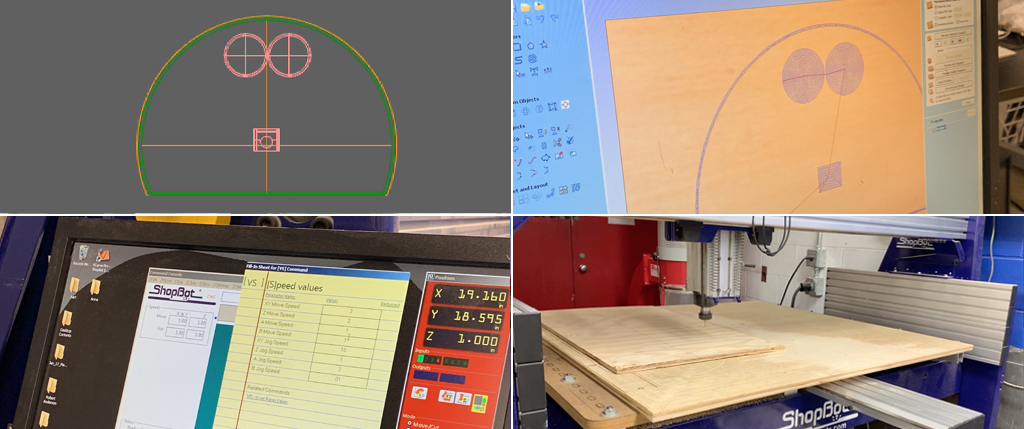
shopbot
With the motor in hand and a stable rotating plate, I returned yet again to rhino in order to extrude a base that would allow me to anchor the motor to the ground. Since the rotational speed of the motor was quite high, I opted to design the base using a piece of wooden Oriented Strand Board. This way, the weight of the wood would counterbalance the rotational speed of the motor and would hold the entire machine in place without the whole machine shaking. I designed 0.3mm pockets to allow all the elements of the machine to be placed in the right place including the motor, two paint containers and the protecting shell. With Rob I programmed both the pocket path and the cutting pat using Aspire and went to the basement lab to proceed to cut the wood using the large ShopBot. However, the machine was sending error messages due to issues we were not able to fix before the deadline, and so we opted to abandon milling the base in wood.
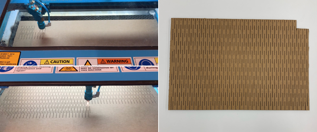
laser cutting
I returned to the lab and cut both the base and the rotating plate in carton board manually. The reason being that since I wanted to be able to paint 18x18” canvas, I needed to cut a 25.5” circle and the maximum size I could cut in Harvard’s laser cutter is 24”. I also found a piece of wood to safely attach the sewing machine motor and to clamp it fixed to the table and safely spin at full speed. This last-minute change, forced me to review yet again the entire design. I designed a pattern that would allow me to laser cut the protecting shell out of 0.3mm cardboard and curve it in a perfect circle. The first trial that I made was unsuccessful because I did not extend the pattern all the way to the edges. The second trial was successful.
integration
Since I had spent so much time in rhino figuring out how all the elements were going to work together, once each of the pieces were successfully executed, it seemed easy for the whole to come together in an organic way, however a series of problems started to emerge.
First, the little piece I welded the metallic plate to the sewing machine motor became loose and eventually broke. I had to go back to CBA’s lab to find alternative strategies to weld the plate. Back in Harvard lab, I assembled the newly welded motor to the painting machine and succeeded to execute a first painting by manually injecting paint using 10ml syringes. The result was beautiful. I opted to make another manually injected trial using black and white, but for some reason, at midnight, the sewing the machine motor stopped working in the process and there was no way of turning it back on.
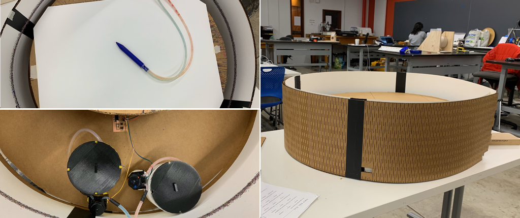
To stay focused, I decided to work on integrating the pumps and the paint containers. I tried adding water to the 3d printed containers, but 3d printed pla IS NOT hermetic. I chose to get two plastic cups, fill them with paint and placed them inside the 3d printed containers. Then, I installed the pumps, connected them to the board and powered the entire mechanism. One of the pumps was working perfectly, but the other one failed to suction paint. I removed the pumps, cleaned them and dissembled the tubbing and realized that I needed a filtering system as small pieces of solidified paint were blocking the pump. For this I used a 3x3cm piece of fine fabric mesh to each of the suctioning silicone tubes.
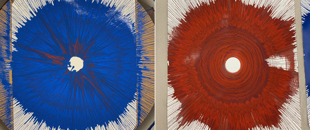
The next day, I spoke to Rob about the problem with the sewing machine motor. After inspection, he concluded that I had simply burnt it. He was generous enough to find another sewing machine motor, which I then had to take again to CBA’s lab and take care of soldering for a third time. Back to Harvard lab and only a couple of hours away from final presentation, I was finally able to do a first fully integrated trial. For the first trial I added blue to paint container and pump A and red to paint container and pump B, the result is a painting with dominant blue color. I then switched the colors, and made a second trial, the resulting paint shows dominant red color. This means that for some reason, there is still an issue with regularly pumping the paint, as my original code turned each pump on and off at identical intervals. Some further research is necessary to better control paint mixing. Also some for future research, I would like to add a x-y axis to the painting machine in order to mechanically control nozzle movement and speed. However, I am satisfied with the final result and extremely grateful to How to Make Almost Anything for giving me the opportunity of integrating its community.
what does it do?
Color Theory IV is an ongoing body of work I have been developing since 2011. For How to Make Almost Anything I created centrifugal painting device which is going to help me further my research.
who's done what beforehand?
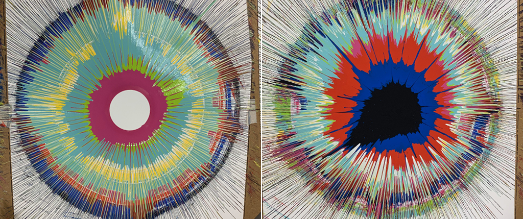
Robotic painting machines are not new. Many different iterations have been developed in the past, including commercial printers or robotic paint systems largely used in the car industry for exemple. Damian Hirst experimented with centrifugal drawing in 2002 (I saw the half of the moon). In 2011, Benjamin Grosser exposed an interactive robotic painting machine that uses artificial intelligence to tell the robot to make its own artistic decisions. The machine is equipped with camera, microphone, mixer, speakers, projector, oil paint, canvas and a custom software. The robot is programmed to listen to the environment and transforms what it hears into art, which allows collaboration with musicians. Another approach is Dixit Algorizmi Gallery in 2017, which developed a series of sketching robots equipped of cameras and robotic arms that sketch portraits using advanced algorithms. In 2019, Liu Xiaodong proposed a robotic painting machine that used images set to a webcam and abstracted it on the canvas.
what did you design?
My design intention is to start the painting at the largest point of the circle using 100% color A and then as the circle becomes smaller, it gradually mixes a decreasing percentage of color A with an increasing percentage of color B. In that way, the smallest point of the circle, at the end of the painting, only 100% color B is used.
For this, I designed two independent mechanisms. The first one is a set of two solenoid pumps which are programed to alternate at different intervals. The paint then goes through a mixing chamber. The paint is then released on a rotating surface. For the future, I would like to integrate an X axis to perfectly control the release of paint and to potentially actuate painting processes and speeds using some form of sensing mechanisms. I would also like to grow in size.
what materials and components were used? where did they come from? how much did they cost?
1.75 mm PCL filament. Ebay. $12.99
4 sheets 24x18 of 0.3mm Cardboard
2 peristaltic liquid pumps 5V to 6V DC power. Adafruit. $25
Tiny 45. Fablab. $1.50
2 Mosfet. Fablab. $0.26 each
Regulator 5 volts. Fablab. $0.45
Capacitor 1uF. Fablab. $0.05
Resistor 10h. Fablab. $0.01
2x2 header or 5.5mm/2.1 plug. Fablab. $0.66
2x3 header. Fablab. $0.60
Bouton. FabLab. $0.84
0.6mm clear silicone soft tubing. Amazon. $7.39
9v power cord. Amazon. $7.99
10x01 one sided coper board. Harvard Lab
USB battery. Harvard Lab
sewing machine motor and cables. Harvard Lab
Gaffer tape. Harvard Lab
Watercolor paper. Harvard Lab
3x3cm of Micro tulle fabric. Harvard Lab
what parts and systems were made? what processes were used?
Global 2d and 3d design. Rhino
Paint containers. 3d printed
Mixing chamber and Nozzle. 3d printed
Microcontroller board design, milling, soldering and programming
Peristaltic pumps Coding using Arduino
Laser cut : exterior shell
ShopBot using Aspire : base (big ShopBot was having problems so we had to abort milling)
Rotating plate motor : metal cutting and welding
what questions were answered? how was it evaluated? what are the implications?
There were a lot of complications. I designed the project around a wooden based which included subtractive method of fabrication. The piece to mill did not fit in the small ShopBot in the science center, therefore, we had to use the big one in the basement. Unfortunately, the machine was sending a lot of error messages, so we decided to abort fabrication. This changed the entire design, which had to be redesigned in rhino. Once everything was fabricated, and three trial paintings were executed already, the motor of the rotating table burnt without possible repair. We had to look for another motor and redo the welding and follow the entire process a second time (actually a third because the first welded piece broke off due to weight). Then the coding of the pumps was also complex, the first board designed, burnt. A second board had to be milled and soldered. However, the pumps were having difficulty turning on and off at different intervals. So we had to provide current to the tiny 45 independently and the pumps only worked “correctly” when supplied with 9 volts instead of 12 volts. I am still not fully satisfied with the mixing process; further research is needed. Also for the coding, I had initially calculated a two minute choreographed program to allow a gradual gradient of colors; however, this never worked and we had to return to a more simple 50%-on / 50%-off program, but I have the impression that one pump is always more dominant than the other, which means that they potentially still have difficulty sharing power. All this said, the result is interesting.