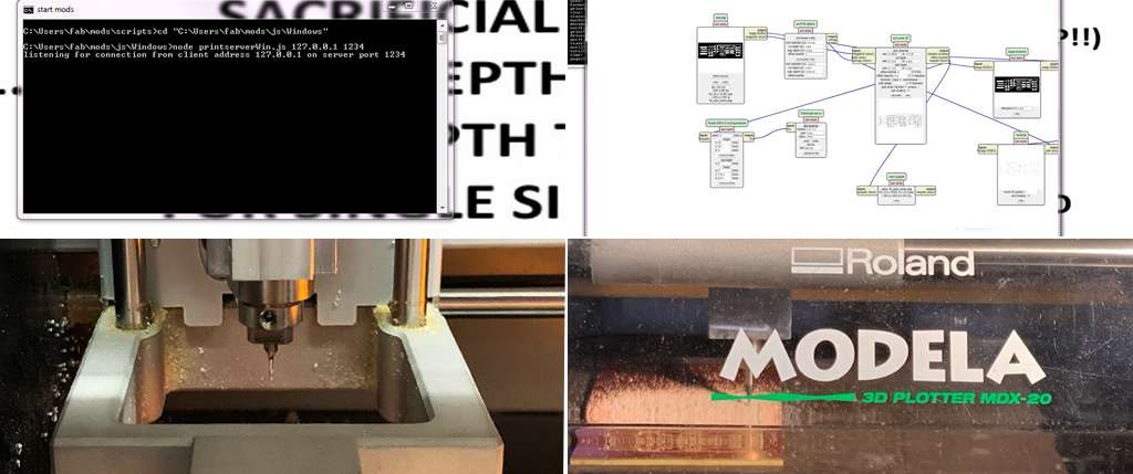
The process started in the Science Center lab. I experimented using a Roland SRM-20 and Roland MDX-20 milling machines. They both have very similar methods. I run Modserver in order to connect the milling machine to both the computer and the server. I then run the local mods program PCB_Harvard_SRM20, and opened the Web socket windows connected to the server, which has already parametrized the specific cutting instructions. I requested the machine to “move to origin” to make sure it was synchronized.
I then added double sided tape to the single sided circuit board to be cut and placed it strongly on the sacrificial layer installed in the milling machine. The process that follow was done in two steps, first I had to mill the design of the circuit board using a 1/64 tool and then I cut the board to the desired shape using a 1/32 tool. I first imported the .png file contining the desing to be milled, made sure that the 1/64 toolpath was chosen and calculated. I used the screwdriver to insert the 1/64 tool into the machine making sure it was higher than needed. Clicked on “move to origin” to see where the tool would land on the circuit board, and changed x and y axis coordinates to avoid waste. I then gently released the 1/64 tool until it touched the board and tighten it. The board was ready to be milled, I launch the process. The machine took care of the miling.
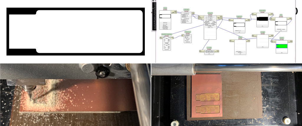
After it was done, I used the vacuum cleaner to remove waste material. Changed the milling tool to the 1/32 cutting tool and imported the .png cutting file following the same procedure. Back to origin, I made sure to select the 1/32 cutting file parameters in the server pre-parametrized web socket, calculated it and launch the cutting process. Once it finised, I removed waste material with the vacuum cleaner and repeated the entire process three times.
soldering
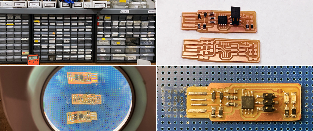
With the circuit boards cut, I proceeded to cleaning them using alcohol and ra rag. I then used sanding paper to clean up loose copper fibers and eliminated with a knife copper elements that were not needed for the in-circuit programmer. I selected the different components: 1x ATtiny 45 or QTtiny85, 2x 1k Ω resistor, 2x 499 Ω resistor, 2x 49 Ω resistor, 2x 3.3v Zener diods, 1x red LED, 1x 100nF capacitor, 1x 2x3 pin head.
With all the patience in the world, at first I tried using the microscope to better control the soldering process, but I was not able to clearly see what I was doing. After unvoluntarely remocing the coper surface due to over exposure to heat and damaging two boards, I decided to work with a lit magnifier glass available in the lab. This time I felt I had more control. I first added a small amount of solder on the board and then using the tweezers, I carefully put in place the component. This was the most challenging part of the process as the components are very small. Held from one side, it was easier to correctly attached the other side and then to go back to the first side to add some extra solder. I followed the entire diagram to solder all the elements. When I tried connecting the programmer to my computer, the red LED did not lit. After getting help from Rob, I realized I had not created the bridge to temporarily feed current to the pin to allow the programmer to be programmed.
programming
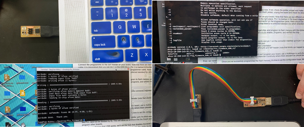
To install the software, I installed CrossPack in my mac and tried to follow the instructions on the terminal, but for some reason, the programmer was not being recognized. We therefore decided to use the lab’s computer. I connected the an already programmed programmer directly to the computer and used an USB extension cable to connect my programmer. At this time the red LED in my programmer lit. I then connected the ISP headed on my board and the USB programmer and in the terminal, I typed “makefile” to import. The computer recognized the programmer. I the typed “make flash” and “avrdude” and “make fuses”. At this point, the programmer was supposed to be already programmed, I double checked in ma device manager / USB devises and in fact my programmer was recognized. Installing the software was not a very clear process and I don’t think I would be yet able to do this on my own in the future. I finished the process by removing the temporary soldered bridge.