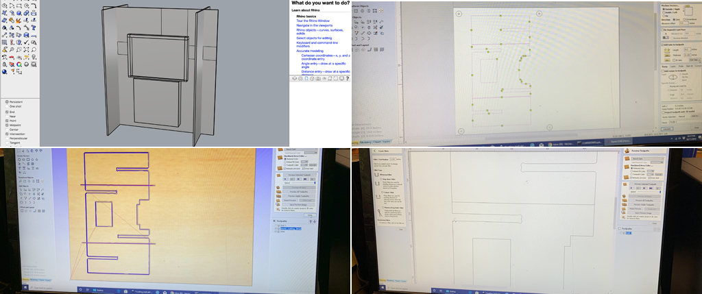
I started by sketching the design using Rhino. To avoid wasting material and to test my joint calculations, I opted to first fabricate a miniature prototype. I exported the rhino file in .DXF format. I opened a new file in Aspire, which is the software that generates the toolpaths of the ShopBot in Harvard’s lab. The software asked me to enter the exact dimensions of the piece of wood. Since, OSB is a raw uneven material, I used a caliper to identify the average width. I entered 26”x18”x0.435”, pressed OK and The new file was created. I then imported my .DXF file and placed it in the right corner to minimize material waste.
drill path
I created a drilling path for 4 screw holes measuring 0.4 making sure they were placed outside of the geometry and away from the cutting path. The role of these screws is to securely fix the material on the machine during the cutting process. I specified 0.438 as drilling width (a little bit bigger than the actual material) and the end mill (up flute + speed). Then I calculated to process the job, previewed the path in 3d, named the path and saved it in a flash drive.
milling path
After I went back to the 2d view, selected the entire geometry to make sure it is closed, and then started designing the profile milling path. In the sub-menu, I chose in the fillet options, the T-bone finishing for internal square angles, and normal for external square angles. This to facilitate assembly. I defined the cutting path to 0.438 (also little bit bigger than the actual material), 3 time path milling process, selected the path outside of the geometry and added tabs (avoiding strategic corners) to hold the individual in place during the milling process. Then I previewed the job in 3d, named it and saved the tool path in a flash drive.

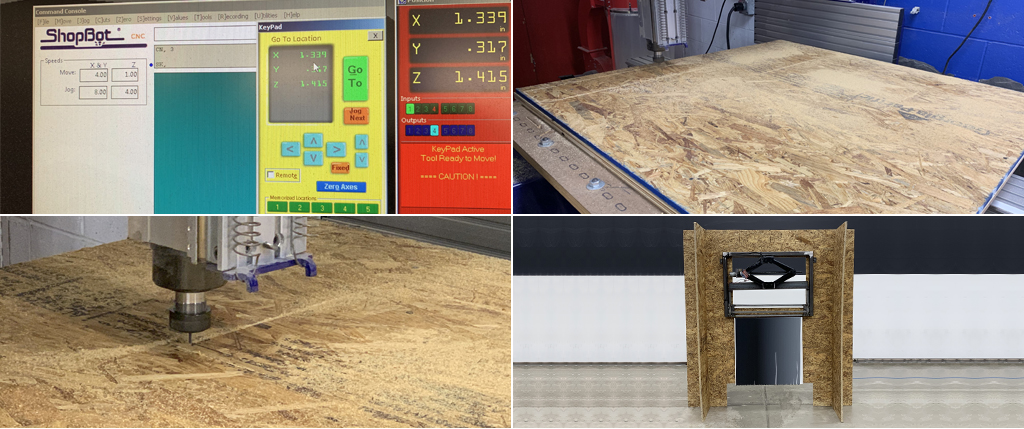
shopbot : miniature prototype
I then went to the smaller ShopBot, turned the key and turned the machine on, made sure the mill end was correct and installed the piece of 26”x28” wood on the bed. I launched the ShopBot program, clicking on the yellow box I opened the axis controllers and using the arrows I positioned the mill the closest possible to the right corner of the material. I set x and y axis to zero. Then I placed the mill towards the center of the piece of wood to zero the z axis. Then, I place the mill at the origin. For security, I placed two screws on the outer reaches of my piece of wood, to hold the material. Then I double click on the file to bring it into the ShopBot, placed the safety guard and click start. The first time, I launched the machine, I received a VS-Setting to Lower Limit (.05)! error message. After troubleshooting, we realized that the speed of the path was incorrect because I used Aspire in a computer that had not been initially set for our exercise. With the help of the Science Center team, we fixed the issue and this time the machine successfully run the drill path. I then inserted the screws, imported the cutting file and run the file in the air to double check the cutting path. I then launched the milling path. Finished, I vacuumed the extracted wood dust, unscrew the prototype parts form the ShopBot and proceeded to assembly. My calculation for the joints was good. I therefore proceeded to adapt my file to the 4’x4’ ShopBot in the basement of the Science Center.

shopbot : size-one prototype
With the geometry at the right scale and after measuring the width of the material to be cut, I created both the drill and the filling paths using Aspire and saved them in a flash drive. Then, we went to the basement, imported the files to the ShopBot, zeroed our x, y and z axis, installed a piece of 4’x4’. For securing reasons, we decided to run the drilling path in the air and to mark them using a marker and to drilled 4 screws avoiding the marked points to hold the material in place. At this point we realized that the ShopBot was not recognizing the parametrized speed, probably due to incompatible updates in the software. We proceeded to introduce the correct speed (18000) manually into the program and launched a second test. This time, the speed was perfect. We launched the drilling path and followed the same procedure as the miniature prototype. After both pieces of wood were successfully cut, and the ShopBot vacuumed and cleaned, I returned to 102 lab, assembled the pieces and installed the painting mechanism and canvas making sure it was leveled.