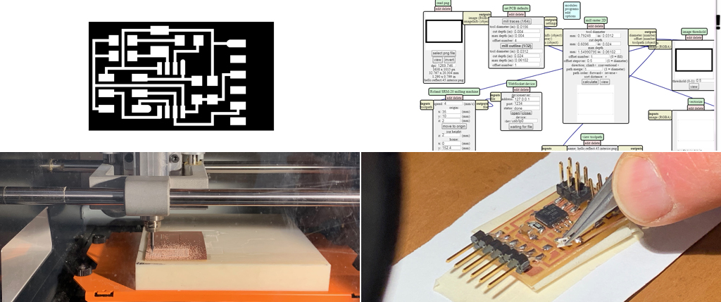
This weeks project consisted in milling, soldering and programming a microcontroller board in order to read some form of input. I chose to use a phototransistor to read to amount of light using 45 tiny microcontroller, and for an LED to turn on and off depending on the amount of light the transmitter was reading. I started by saving the traces and interior of the baord and listing the components I would be using : 2 resistors 10k, 1 capacitor 1uF, 1 tiny 45 microcontroller, 1 LED light, 1 ISP 2x3 header, and FTDI connector. I then went to mill both the interior and traces of the board using the standard procedure. Once milled I proceeded to solder the components on the board and then I plugged my programmer into the computer to try to program the board.
coding
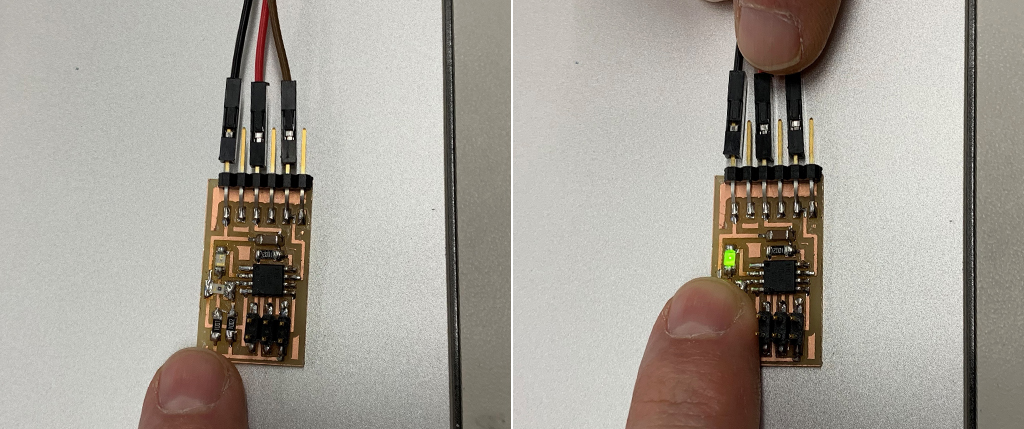
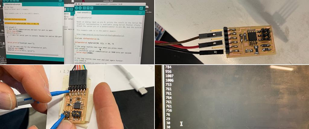
I used Arduino libraries to compose my own code. The goal was for the phototransmitter to read light. When a certain measurement of light was reached, I wanted the green LED light to be turned on. Doing the programing, I understood that the phototransmitter read around 400-500 at normal lighting conditions. And as we covered the phototransmitter to eliminate the light the measurement went up to 850-1000. I therefore decided that when the phototransmitter read 900, the LED would turn on. Once my code was written, I was ready to program
/*
AnalogReadSerial
Reads an analog input on pin 0, prints the result to the Serial Monitor.
Graphical representation is available using Serial Plotter (Tools > Serial Plotter menu).
Attach the center pin of a potentiometer to pin A0, and the outside pins to +5V and ground.
This example code is in the public domain.
http://www.arduino.cc/en/Tutorial/AnalogReadSerial
*/
#include
SoftwareSerial mySerial(1, 2); // RX, TX
// the setup routine runs once when you press reset:
void setup() {
// initialize serial communication at 9600 bits per second:
mySerial.begin(9600);
pinMode(3, OUTPUT);
}
// the loop routine runs over and over again forever:
void loop() {
// read the input on analog pin 0:
int sensorValue = analogRead(A2);
// print out the value you read:
mySerial.println(sensorValue);
delay(1); // delay in between reads for stability
digitalWrite(3, HIGH); // turn the LED on (HIGH is the voltage level)
delay(1000); // wait for a second
digitalWrite(3, LOW); // turn the LED off by making the voltage LOW
delay(1000); // wait for a second
}
programming
I plugged my programmer and attached it to the new board to upload the code. I received a lot of different error messages. At this moment, I realized I had used an infrared phototransmitter, and that I had solder the LED light heading the wrong direction. I removed these two components and solder the correct ones in the right direction and went back to Arduino. I then went back to the programming phase. This is challenging, because even if code is correctly written and components correctly soldered, error messages are common, most of the time due to connectivity. One of the error messages was the fact that the clock needed to be reset and burn the bootloader. After many trials, the board was programed and the readings were correct.