Introduction:
This week we were tasked with cutting using a vinyl cutter and a laser cutter. We were given a lot of freedom on what this would look like. For this week, I was inspired by retro and old-timey space themes, and wanted to center my work around that.
Vinyl Cutting
Plan: A retro name laptop sticker
I loved the retro family of fonts, and wanted to spruce up my laptop this year with my name.
Workflow
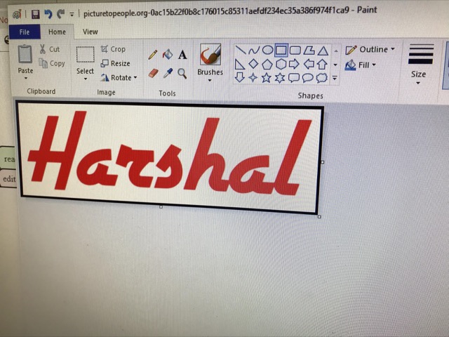
I began with looking up online text to transparent PNG generator. I found this, and it had the retro font I liked (Airstream).
I took this PNG and added a box around it in Paint, to make it easier to remove from the vinyl after cutting.
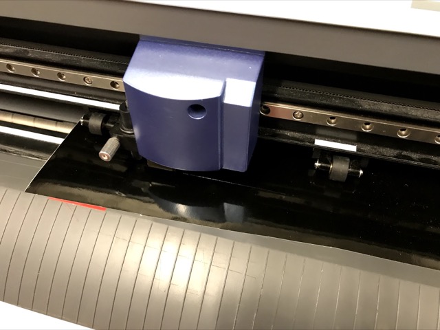
I then used the CBA Mods tool to get it on the vinyl cutter. I used the default settings for all parameters, to form a baseline.

Then I was ready to go, and sent the command to the printer.
I realized the default setting of 50 strength was not good enough. The transfer paper did not pull off all the vinyl.
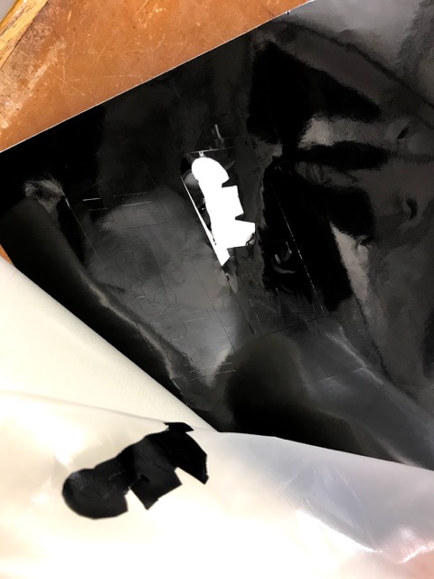
I then changed the cut strength to 75. That also did not do the job, and ended up at a strength of 100.
Sticker Transfer
Using a bit of transfer paper, I got the rectangle with the letters off the vinyl backing.
The rectangle was very helpful with this step, as everything came off in one go
Thanks to the rectangle, I had an intermediary step where I could take the rectangle off on the transfer paper, not on the laptop.
Weeding from the transfer paper was a simple task, and the transfer paper let me bend and move parts to make it easier.
Some small bits did not cut properly, but I think that was because of the challenging geometry of the text.
I then stuck it to my laptop with no problems!
What I would do differently
Laser Cutting
Plan: A build your own capsule
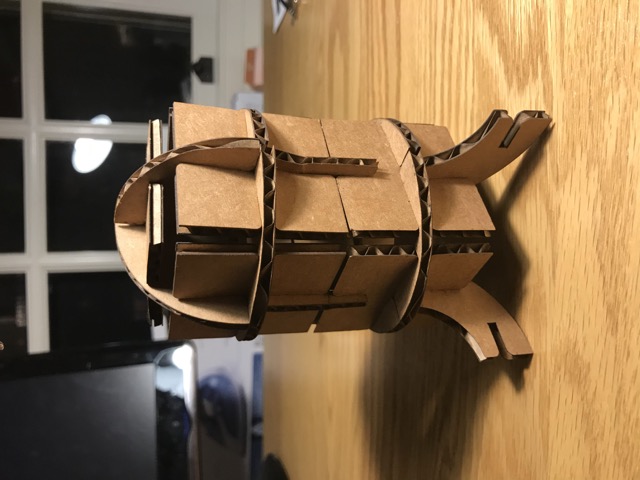
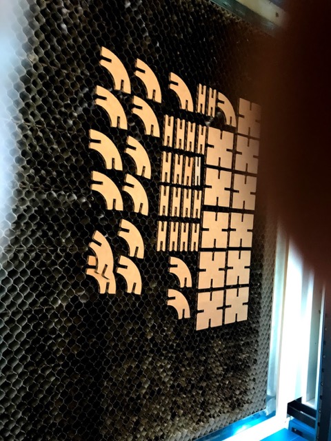
On the retro theme, I wanted to make a customizable time capsule, where you can change the size, and hide things inside. I was inspired by the following picture:
To ensure that it was customizable, I began thinking about the types of "pieces" this would need.
Kerf Testing
However, before doing all of this, I decided to figure out the kerf.
I began by designing a kerf measuring comb. Each interval was of an increasing dimension. The idea was that I would cut two of these combs, and see which dimension gave the best fit between the combs. I centered the dimensions by measuring the cardboard to get an estimate of the thickness.
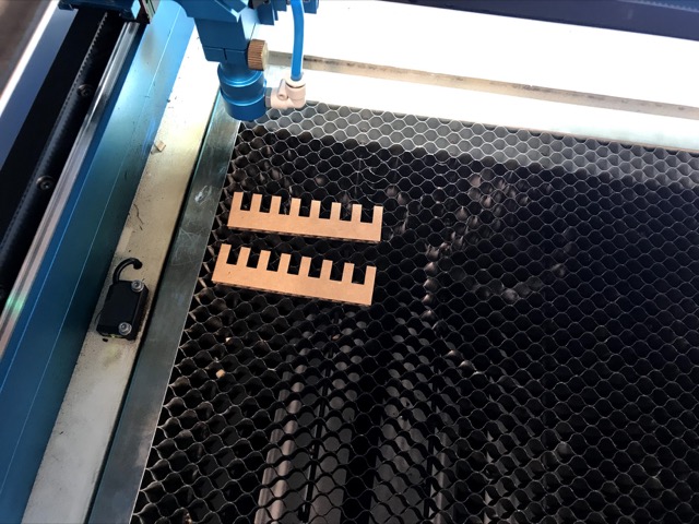
After cutting the above two combs, I realized I had read the ruler wrong, and had centered the slot dimensions around 0.25 inches instead of 0.125 inches. This was extremely embarrassing. I redid the sketch and cut two more combs out.
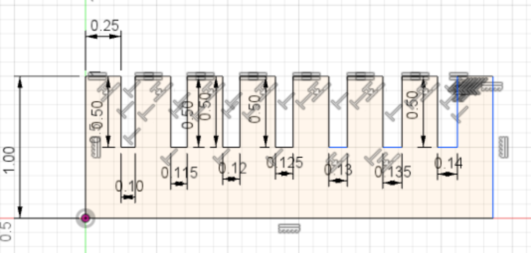

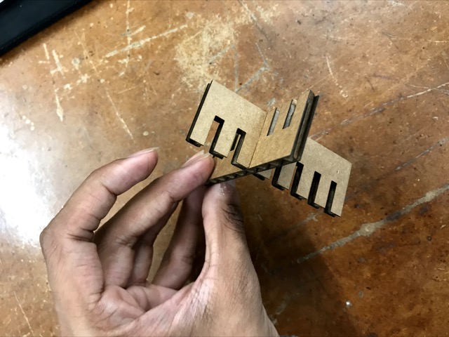
After that, I tried inserting the comb slots together until I got a snug but comfortable fit. The dimension I liked the most was 0.13 inches. This meant that the kerf was 0.0025 inches.
Design
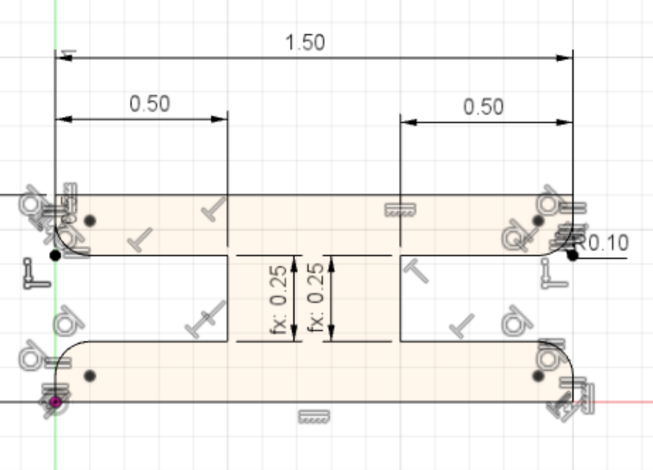
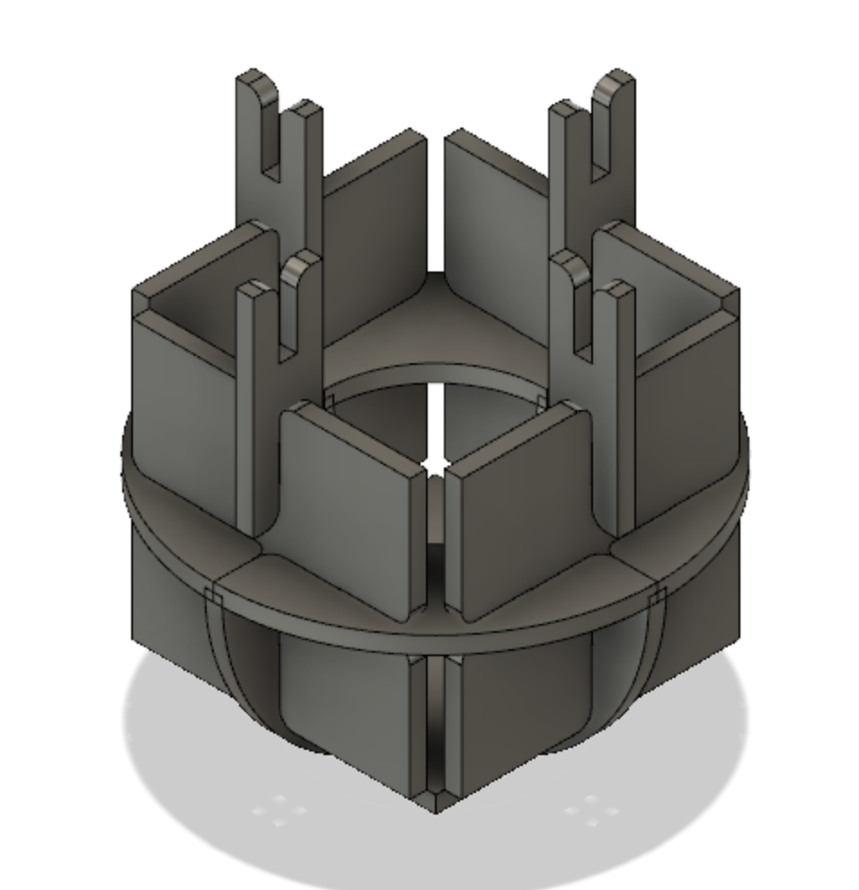
With this knowledge, I could start designing my capsule pieces. I began with the square 4 point connector. My initial sketch was straight forward. I wanted the driving dimension of my framework to be 1 inch. Each slot would have a 0.5 inch length slot, so the pieces would interlock for 1 inch. That meant my square had to be 2 inches in length.
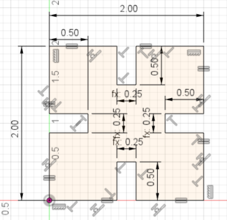
Note the wrong slot length. Thankfully, I used user parameters to make the slot width easy to change

I then added a fillet to all of the slot edges, to make it easier to insert.

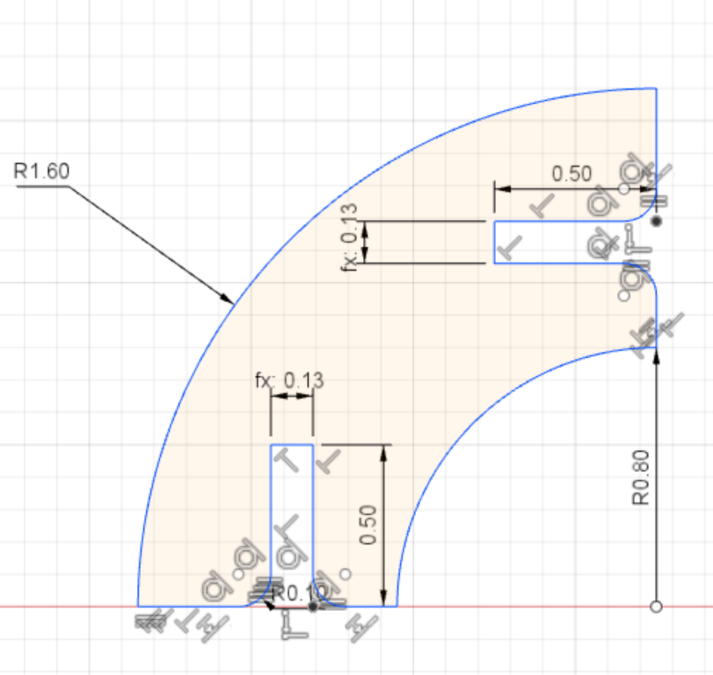
I liked the way this looked. I then started designing the 90 degree connector. I had to keep in mind that the 90 degree connector could not take up too much space, because it would form the inside of the capsule. This was what I settled on.
I then designed the thin, straight connector.
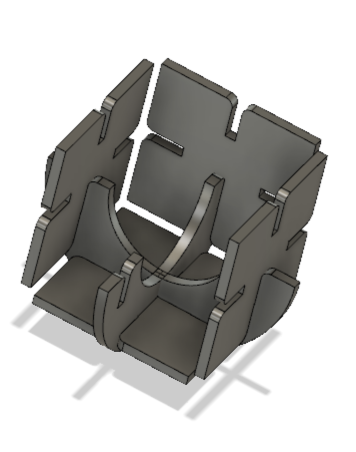
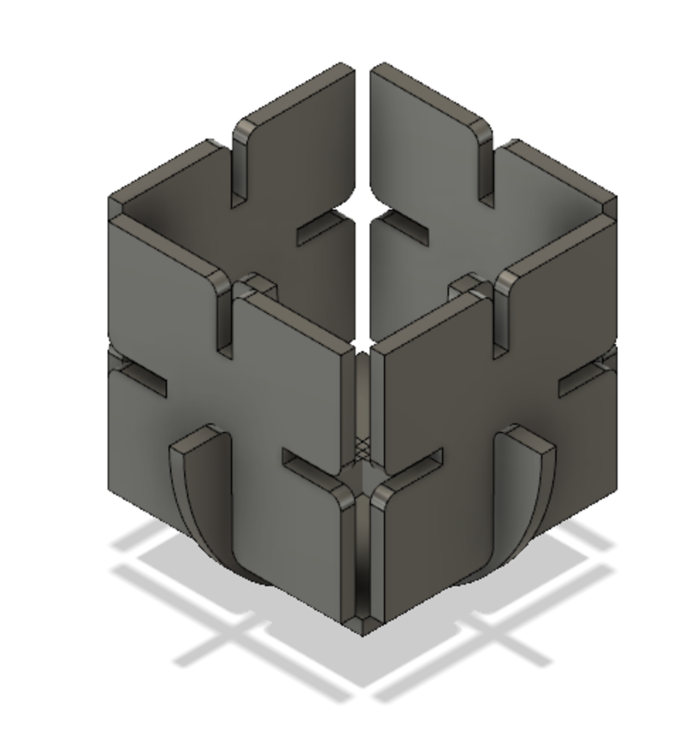
Before cutting anything, I wanted to put it all together in CAD, to see how the pieces interacted with one another.
With fusion 360, this was as simple as importing all parts into one file, and mating them together using joints.
Step 1:
Step 2:
Step 3:
Cutting
I saw that I had to adjust the size of a few of the pieces to prevent collisions. I did that, and then began cutting. As a section, we had already determined that the optimal cutting strength on the Harvard laser cutter was 100.

I then hit the cut button!
Then was the fun part: putting it all together. I ended up making a rocketship after the capsule, as it made for a neat desk decoration.