Introduction:
This week we were tasked with building something that controlled some output device.
Workflow
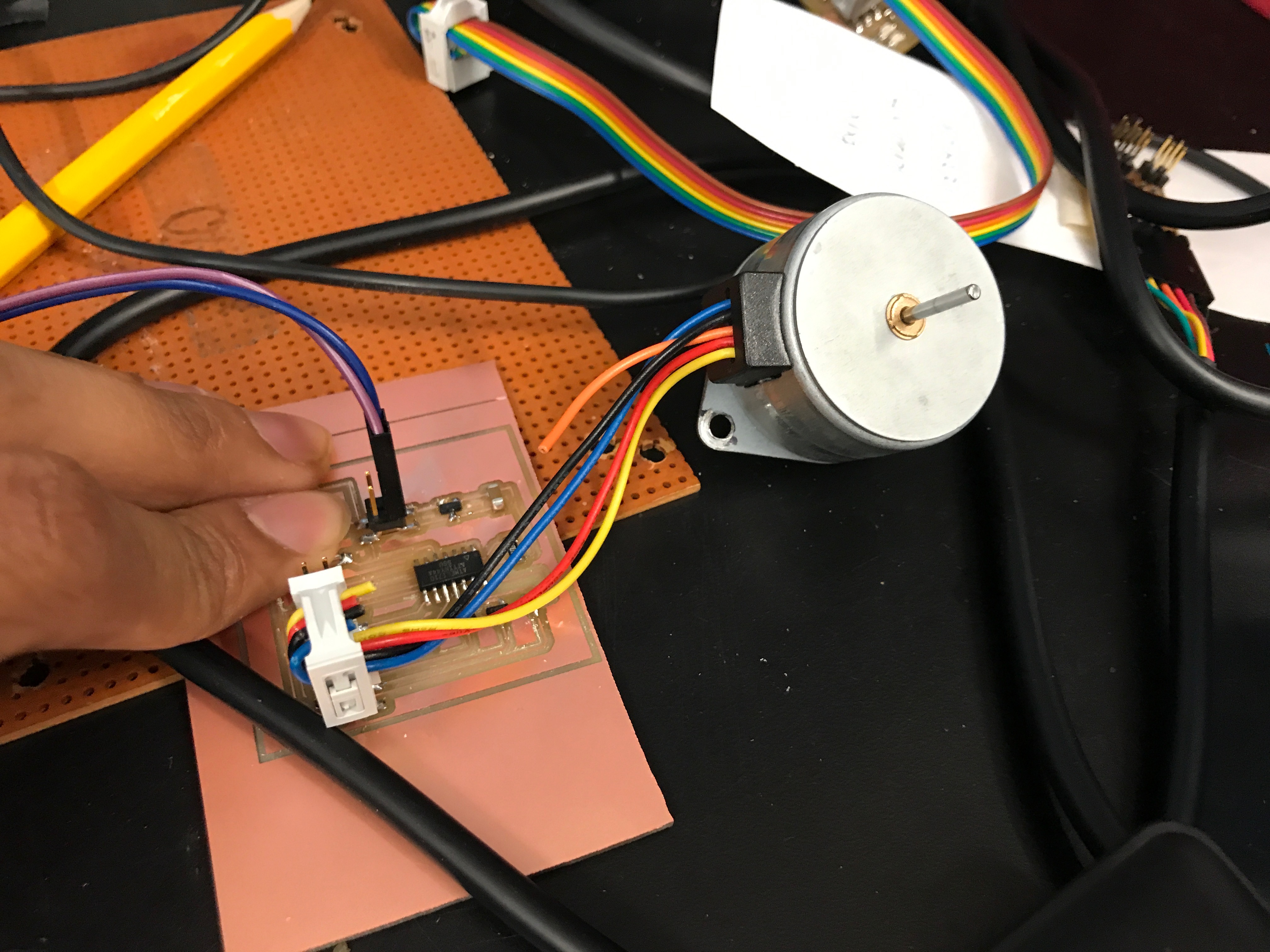
Plan: Experiment with stepper motors in preparation for the final project.
Design
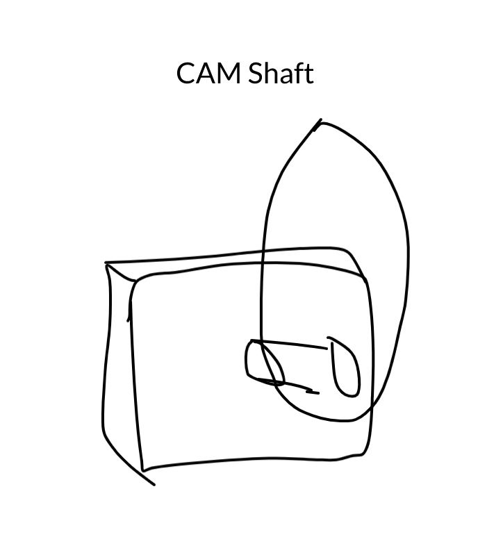
In my final project, to be able to control the movement of plant pods in one (linear) direction. I plan on doing this with a collection of stepper motors and CAMs.
For this week, I wanted to build off of the sample unipolar stepper circuit Neil had on his website. I decided on using a unipolar over a bipolar as I thought the simpler circuit would be easier to debug, and would be a good way to ascertain whether I needed a bipolar stepper for my final project.
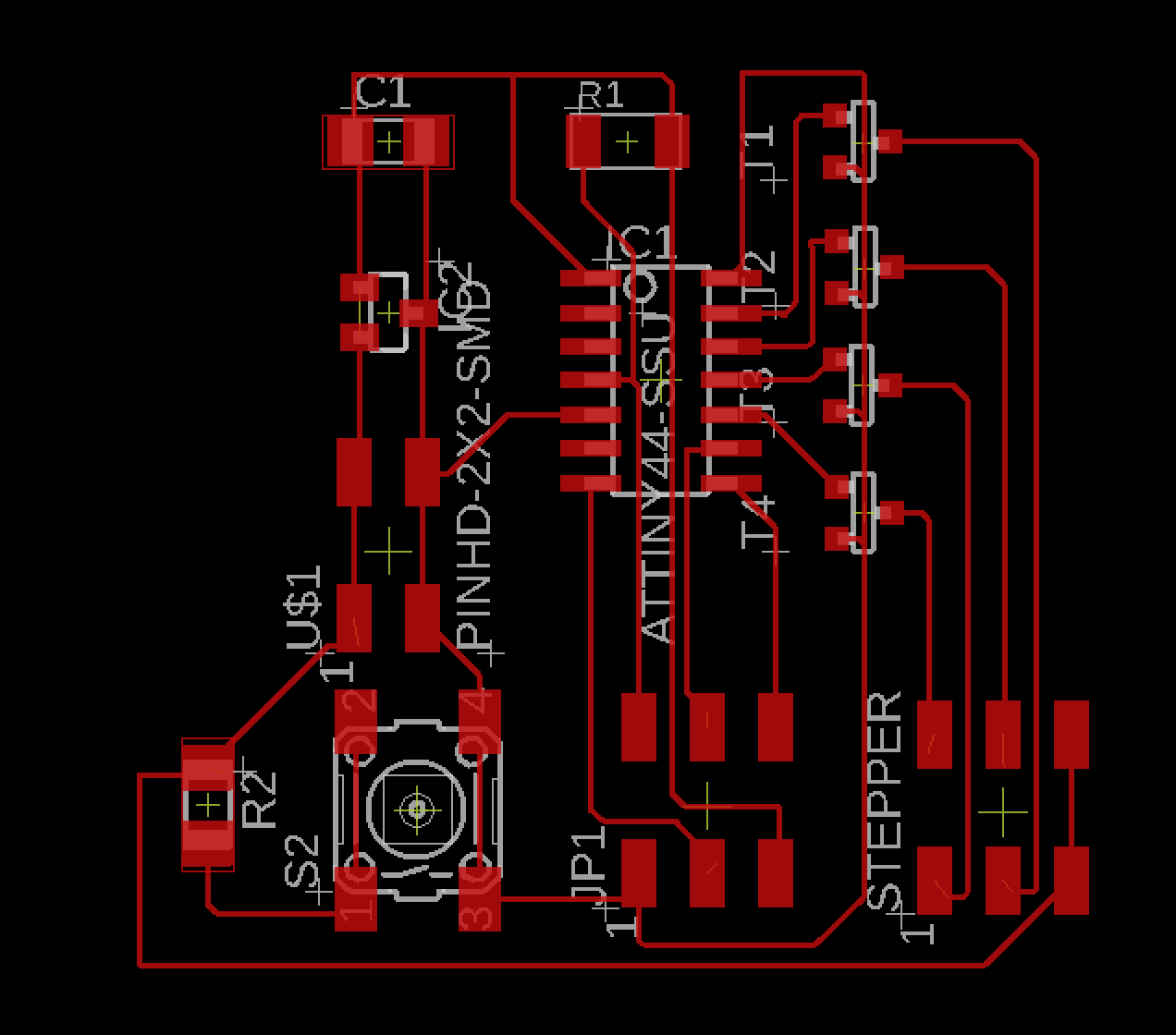
I drew up his schematic in Eagle.
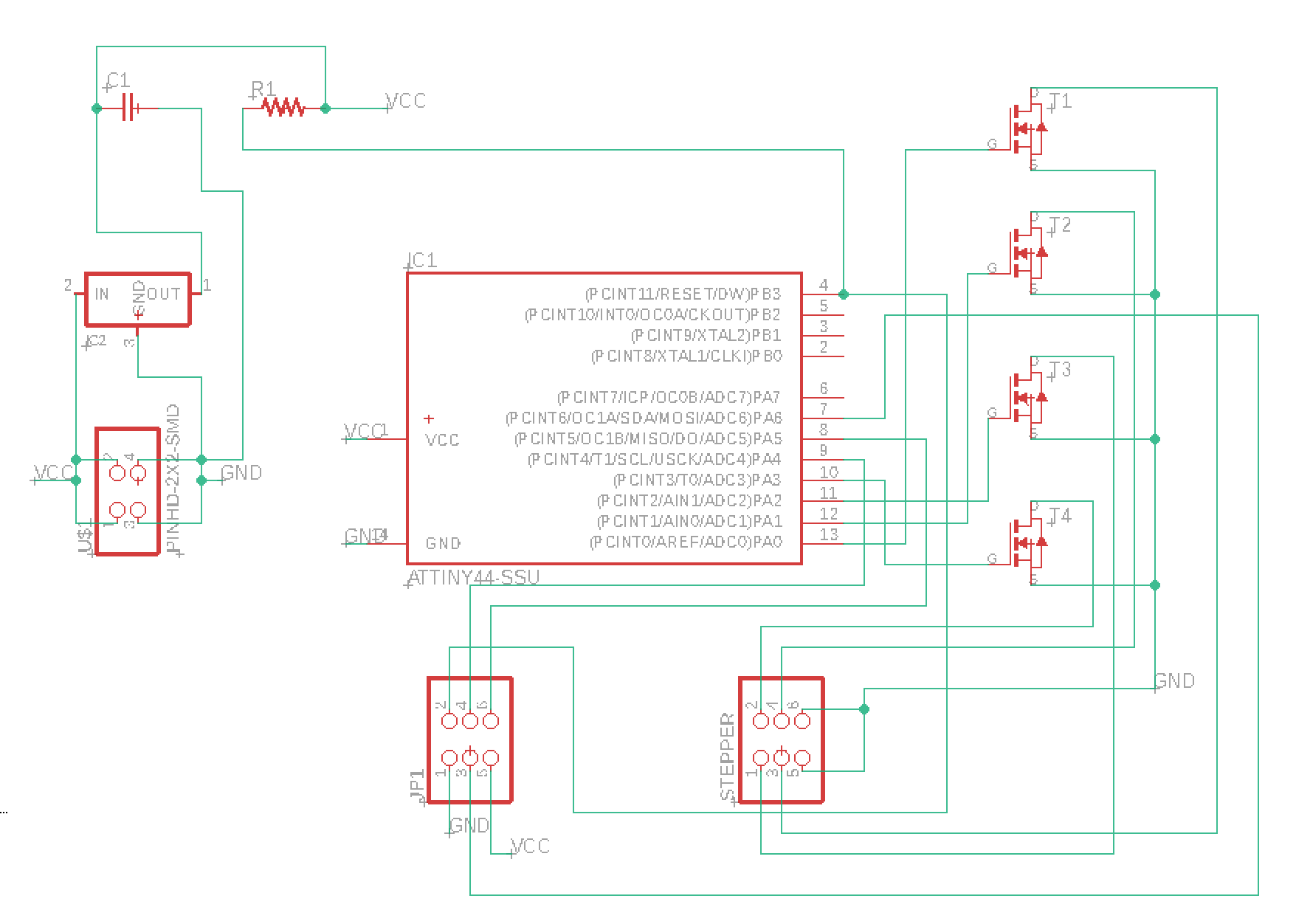
I then decided to add in a button with a pull-up resistor to serve as an input that could control the motor if necessary. Below is a snippet of that.
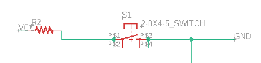
Routing the wires was fairly easy. I followed the compact packaging that Neil used, and added in my button logic on the bottom left.
Cutting & Soldering
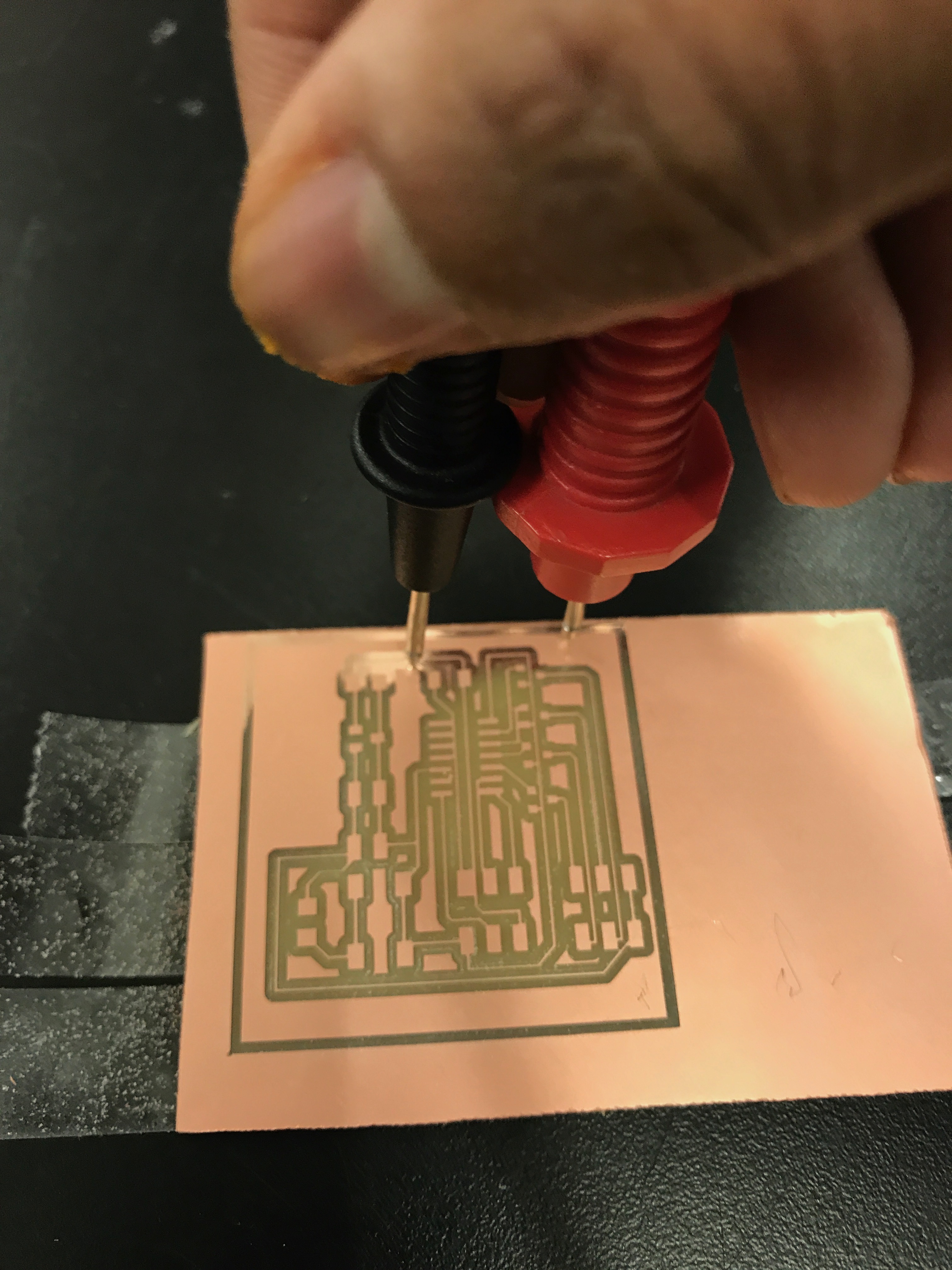
I've decided I do not like PCB mills (just kidding, but not really).
I used the Modelo this week to cut my PCB. The process was fairly straight forward, until I looked closely at my cut, and saw that the upper half was not cutting properly. I hoped against hope that the feint copper I could see between traces was not conductive, but thanks to my multimeter, I was dissapointed. I'm not sure what caused this, as I pressed down on my peice further, and increased the depth of the cut, but nothing seemed to work. I decided to just try cutting it again.

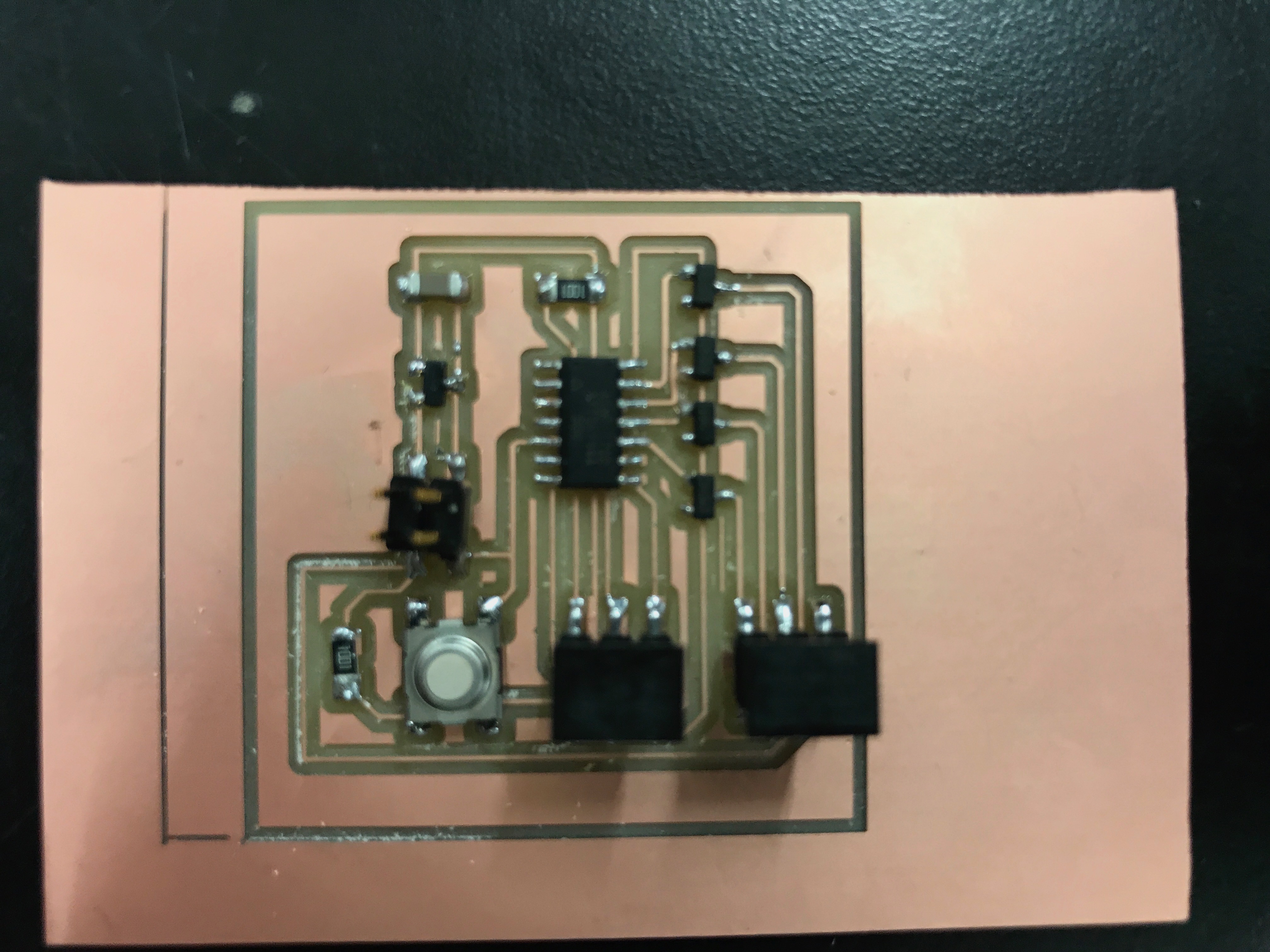
Soldering was straightforward. I had to cut a lot of traces because the mill did not cut the boundaries. My traces were a bit too thin. I also wonder if the Mac DPI issue had anything to do with this (Macbooks have to double the DPI on MODS to ensure the peice was cut to the right size).
Code
I began with the example code, and uploaded that to make sure everything was working correctly. The stepper moved in a wave fairly easily!

I then added my button functionality. I had to think a bit on how to incorporate it into the code. I wanted to first change the while loop in the main itself, but realized that that would only stop the cycling. I then decided to implement my pause logic within the pulse functions. They were simple additions that kept the general logic unchanged.

Then I got to test it!