Sources: 1
What is a register? "Registers are data storage devices that are more sophisticated than latches. A register is a group of binary cells suitable for holding binary information. A group of cascaded flip-flops used to store related bits of information is known as a register." Source
0b00000000 or hexadecimal 0x00Bitwise AND &
Any overlapping bits (bits that are 1 in both inputs) are output as 1 … everything else is 0.
Ex. 0b11 & 0b01 = 0b01
Bitwise OR |
Any high bit in either of the inputs is output as 1 … everything else is 0.
Ex. 0b10 & 0b01 = 0b11
Bitwise NOT ~
All bits are inverted. 0 becomes 1 and vice versa.
ex. ~0b101 = 0b010
XOR (exclusive or) ^
Left Shift <<
Shift the bits of the first operand over to the left by a number specified by the second operand.
Ex. 0b00101 << 1 = 0b01010
Right Shift >>
Shift the bits of the first operand over to the right by a number specified by the second operand.
Ex. 0b00101 >> 1 = 0b10010
Do the bits "wrap around" when you bitshift or are new bits just zeroed?
This was probably the biggest point of conceptual confusion when I was starting out. The technical words take on a different meaning from their coloquial usage.
Every physical IO "pin" — I'm using this word in quotes because it'll mean something different later — on the ATtiny has three features (three bits!) that the microcontroller keeps track of.
The digital voltage value of the "pin" — a read-only input — PIN
A value to potentially write out — read/write — PORT
The direction of the input/output; whether this "pin" is receiving input or sending output — read/write — DDR
I was confused by the terminology, so I think it is helpful to understand what each thing is doing before going giving them names. The first feature is called the PIN. The second feature is called the PORT. And the third is called the "Data Direction" (which is abbreviated to DDR, "Data Direction Register" ).
Any "pin" can be described by 3 bits of data. However these three bits are split up across different registers. Rather than have a single register for each "pin", there is a register for each feature —PIN, PORT and DDR.
So rather than storing these values like 0b100, they are stored in three different registers: 0b10000000, 0b00000000 and 0b00000000, where the bit position in each register maps to information about the same "pin".
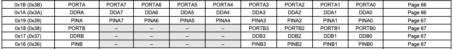
These are the relevant IO registers for the ATtiny.
The other source of confusion is that due to the memory constraints of the ATtiny, these feature registers —PIN, PORT and DDR — are themselves broken up into different registers. For example, on the ATtiny, there is are A and B registers for each of the features.
echo.cNeil introduces a layer of abstraction that makes the code more readable but also obfuscates what is going on.
Let's look at some of the macros.
#define output(directions,pin) (directions |= pin) // set port direction for output
#define set(port,pin) (port |= pin) // set port pin
#define clear(port,pin) (port &= (~pin)) // clear port pin
|= is a bitwise inclusive OR assignment operator. It performs a bitwise or between the left and right operands and then assigns the result into the left.
Both set and output are doing the same thing. They take two 8 bits values, create a resulting 8 bit sequence where all of the positions have OR'd and then assign it into the first variable.
#define serial_port PORTA
#define serial_direction DDRA
#define serial_pins PINA
#define serial_pin_in (1 << PA0)
#define serial_pin_out (1 << PA1)
#define serial_interrupt (1 << PCIE0)
#define serial_interrupt_pin (1 << PCINT0)
These defines make much more sense when we understand the datatype of all the constants from LibAVR.
PORTA, DDRA, PINA are all pointers to binary values like 0b00000000.
PA0, PA1, PCIE0, PCINT0 are all integers between 0 and 7 that indicate a bit position.
PA0 is equal to 0, then serial_pin_in = (1 << 0) which means serial_pin_in = 0b00000001. This helps explain what the macros above are doing. The code set(serial_port, serial_pin_out can be understood as something like 0b00000000 | 0b00001000 which equals 0b00001000.
How do interrupts work? I'll probably have to look at the data sheet for figure out. For now, I will just continue to use the example code.
When the PCIE0 bit is set (one) and the I-bit in the Status Register (SREG) is set (one), pin change interrupt 0 is enabled. Any change on any enabled PCINT[7:0] pin will cause an interrupt. The corresponding interrupt of Pin Change Interrupt Request is executed from the PCI0 Interrupt Vector. PCINT[7:0] pins are enabled individually by the PCMSK0 Register.
GIMSK – General Interrupt Mask Register
Turns on tracking!
PCMSK registers which pin to track (PCINT)
I want to make a program that:
Seems simple enough...
I think I wrote it.
The logic itself is very simple. I declared a global Boolean variable led_on. The code below runs when the button is pressed.
   led_on ~= led_on;
   led_port |= (led_on << led_pin_idx);
https://github.com/osx-cross/homebrew-avr
brew tap osx-cross/avrbrew install avr-gccI copied the default make file and updated the PROJECT to the name of my C file.
I ran make and was met with the message make: *** No targets specified and no makefile found. Stop. Running make blink worked better. But now I have a complier error: fatal error: 'avr/io.h' file not found. avr/io.h is in avr-libc.
avr-gcc -mmcu=attiny44 -Wall -Os -DF_CPU=20000000 -I./ -o blink.out blink.c This
avr-objcopy -O ihex blink.out blink.c.hex;\avr-size --mcu=$attiny44 --format=avr blink.out
avrdude -p t44 -P usb -c usbtiny -U flash:w:blink.c.hex
ls -lha /dev/tty*
/dev/ttys000
system_profiler SPUSBDataType
avrdude -p t44 -P usb:020:041 -c usbtiny -U flash:w:blink.c.hex