Week 06 - Electronics Design
This week's assignment was: redraw an echo hello-world board, add (at least) a button and LED (with current-limiting resistor) check the design rules, make it, and test it.
I finally got my Clank to start working last week, so I was really excited to start making things with it! We had recitation this week where we learned more about how to design your own circuits in Kicad and Eagle. I wanted to try them both out to see which one was easier for me. I think the Kicad interface is nicer to work with, but I was more sure about which components I could use in Eagle, so I used Eagle for the assignment this week. I decided to redraw the board for the ATtiny1614. Here is the original design:
So my goal was to remake this design in Eagle and incorporate an LED and a button as well! First, I imported the Fab library and the ATtiny1614 into Eagle so that I had the components available to use in my design. I first created a schematic:
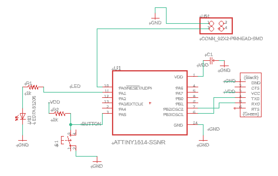
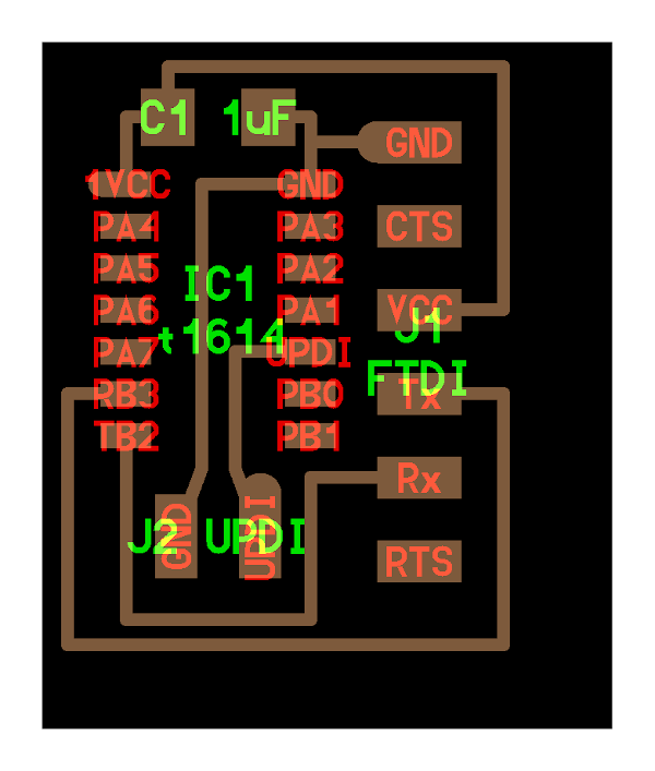
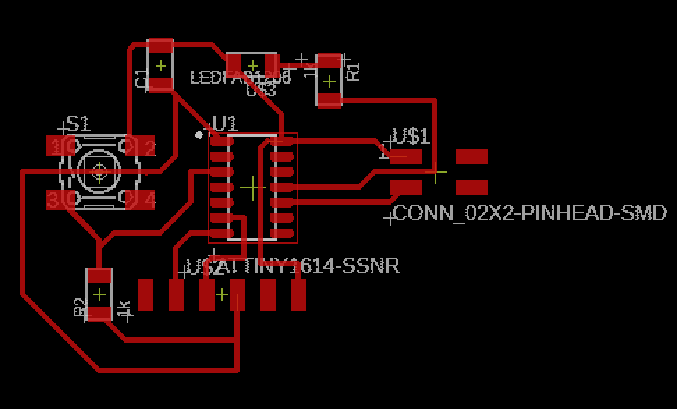
I made sure that I had a current limiting resistor before the LED and that things were connected properly (such as making sure the output of the FTDI was the input of the tiny). Then, I moved on to the making the board. Eagle draws the connections that you made in the schematic, so you just have to wire them up. The tricky part is making sure they don't overlap or touch when they aren't supposed to. It was a bit of a puzzle, but this is the design that I ended up with:
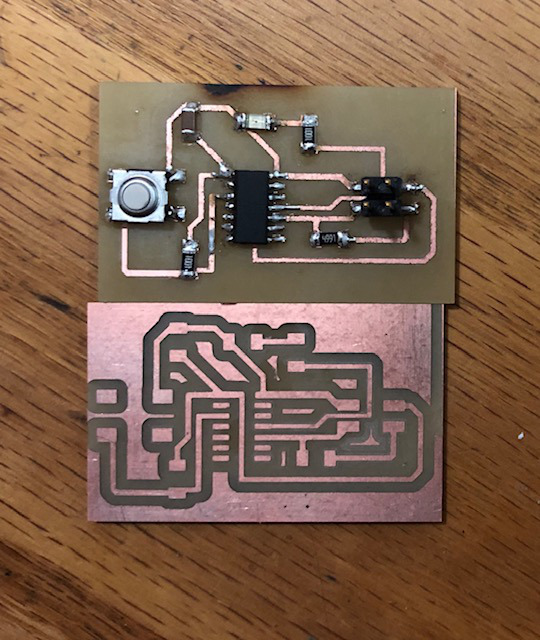
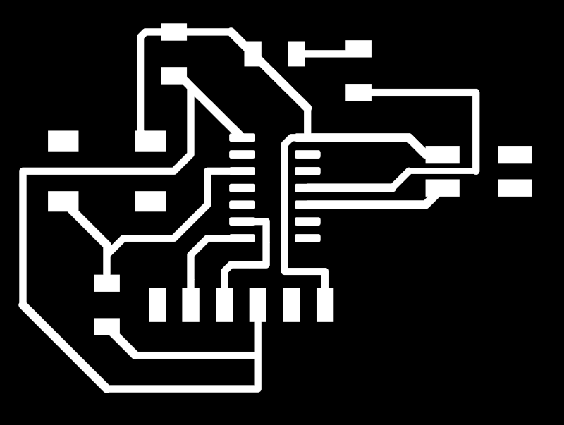
And the black and white image of my design:
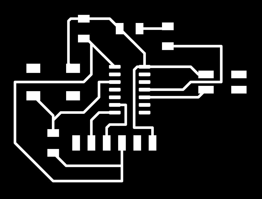
I got this image from Eagle using File>Export>Image. Then I made sure to select monochrome and increase the dpi to 1000.
The next step was kinda tricky, but luckily Omar helped me out. Because the inside cuts and the cutout of the whole board need different bit sizes, I needed two separate png files. This way I could use mods to generate the gcode for one, switch bits, and then use mods to generate the gcode for the other.
To make these files, I used Inkscape. With Omar's help, I opened up the PNG I exported from Eagle. Then, I created a new layer for my outline. I drew a box around my inner cutouts making sure to leave room for the exterior cutout (this is the red box):
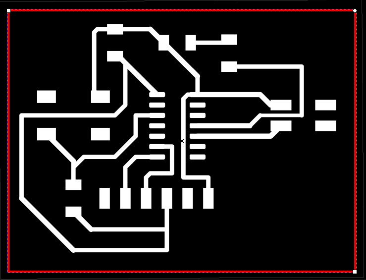
I made sure the box settings were set so that it was just a black, solid outline. I moved it to its own layer. I could now export both layers separately, giving me a cutout and the inner traces as two separate PNGs! When importing these PNGs to mods, I noticed that the dimensions were pretty large (3 ish inches) and realized this was likely because I needed to double the dpi in mods to scale the image down by 1/2. (This was an issue that was brought up earlier in the week, so I knew how to fix it.) This ended up working well and seemed to fit all of my components!
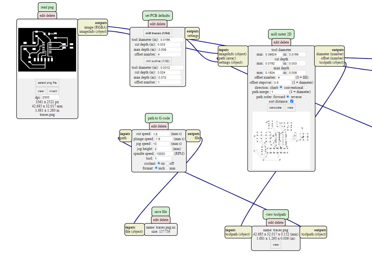
I decided to give the cutting out a go, and I used these mods settings:
I noticed that some of the diagonal wired connections that I had weren't being cut out properly, so I stopped the job. You can see that there are some places where there should be a copper connection, but the cutout was too close together and removed it all:
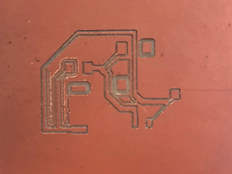
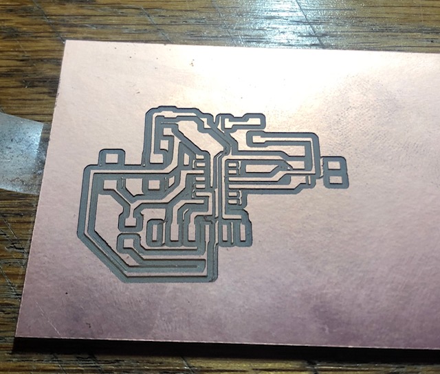
I think this is maybe due to my Clank belts being tightened unevenly, so I will make sure to check those, but for the mean time I used Eagle's Change tool to increase the wire width from 16 to 20/24 depending on the wire. I was hoping this increased width would allow more room for these connections to be made. Here's what the design with thicker connections looked like:
This temporary fix seemed to work! It seems like the channels are connected know, although they are still WAY thinner than they should be. I will be working to fix this asap. Unfortunately, as soon as I started milling my outline a screw fell out of my Clank (I'm still not sure where it came from?), so I stopped the job before things went more wrong. I noted the location and tried to reinsert that as the location when I restarted the controller, but that didn't seem to work :( . I wasn't able to relocate my zero point, so I moved on to soldering without cutting it out since I didn't have time to make another board and wanted more soldering practice.
Here's the board before the soldering:
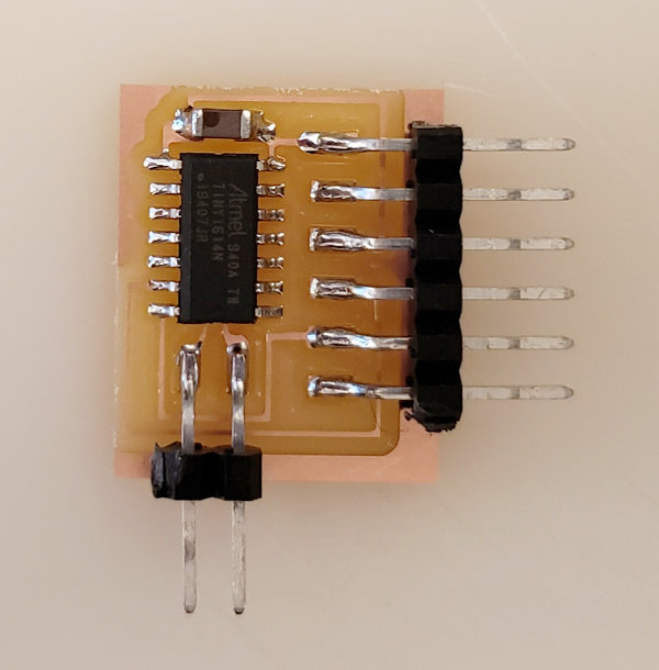
And after soldering and stuffing:
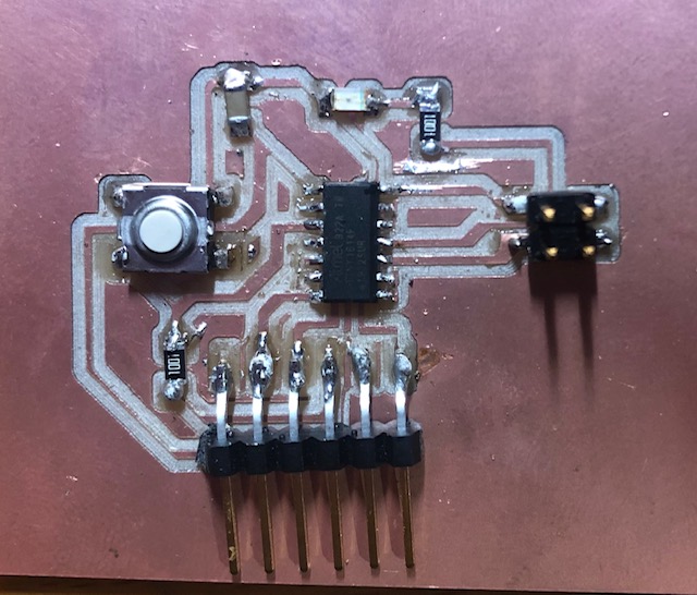
I wouldn't call this my best soldering job, and the ATtiny1614 was especially difficult to solder. I'm thinking I might try to make the footprints for some of the components larger next time. Overall, I learned a lot this week and got a lot of practice. I'm going to take what I've learned from what went wrong and use it to remake this board a lot better in the next few days! Since the traces from my clank were still kinda uneven and too thin, I redesigned this board a bit and milled a few in the arch shops to get more practice: