This week's assignment was: measure something: add a sensor to a microcontroller board
that you have designed and read it.
I really wanted to use this week to make progress towards my final project! I decided to use a potentiometer as my input device to act as a dial since I'm thinking I'll use dials and switches for my final project. I wanted the to read the voltage after passing through the potentiometer and a resistor. If this voltage was over a threshold voltage, I wanted to light either one LED or another as well as change the color of an RGB LED.
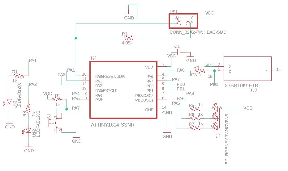
I started by altering the board design I've been using for the last couple weeks. I continued using the ATTiny1614 since I needed all of the pins. Here was my final schematic in Eagle:
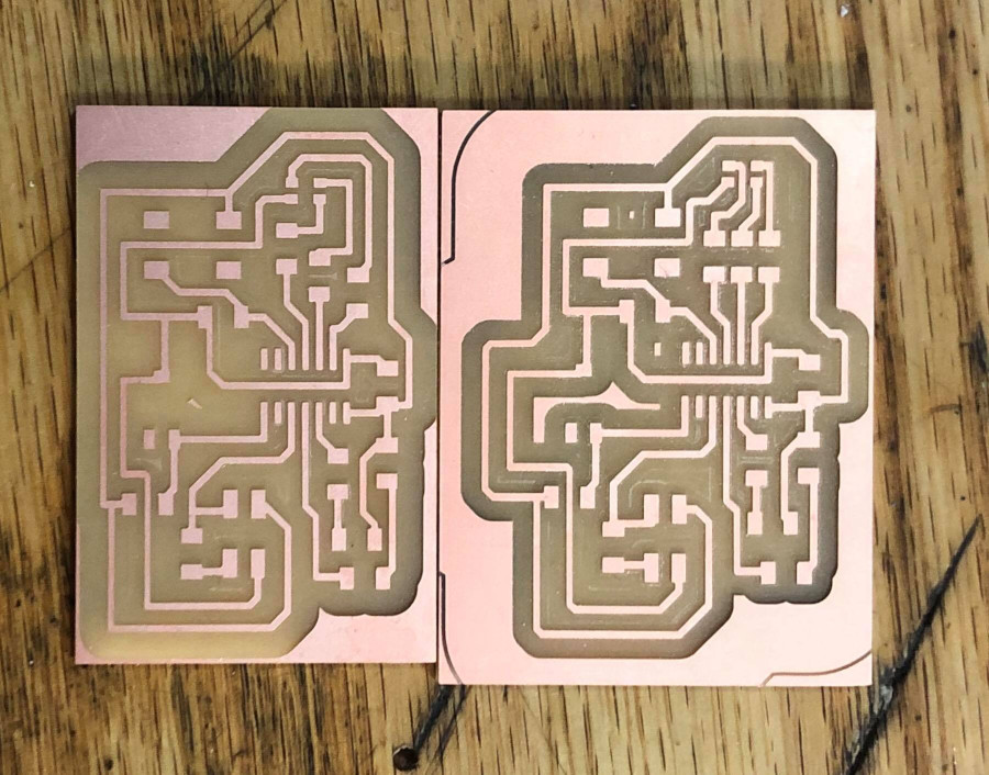
I used the Arch section SRM-20 to mill this week. I made two boards just in case I needed a backup. After the first one, I thought the resistors before the RGB LED were a little too close together, so I moved parts around in Eagle a bit to make soldering easier. I also added a few extra offsets. Here are the two boards:
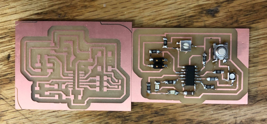
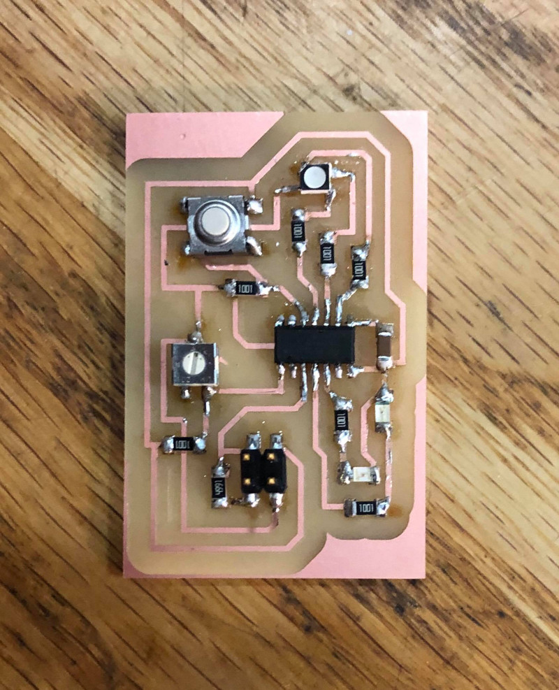
Then, I collected parts and stuffed the board.
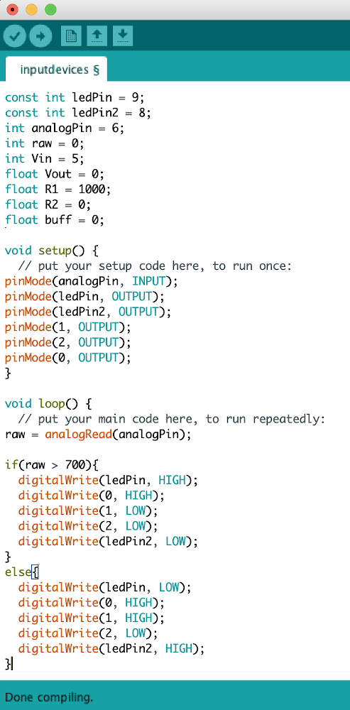
I wrote the code for this assignment in Arduino since it was relatively simple.
I ran the code using the same method as last week and following Zach's tutorial. It worked! Shown below is a video that shows what happens when you switch the potentiometer back and forth causing the voltage to pass through the threshold voltage. To make this circuit better in the future, Anthony recommended connecting terminals 1 and 3 on the potentiometer to vcc and gnd, then read from terminal 2. This would remove the need for the additional 1K resistor that I have and should keep the response roughly linear (assuming linear potentiometer) across the whole range.
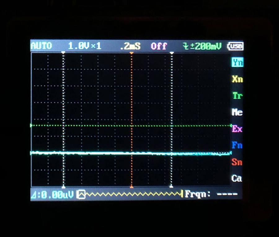
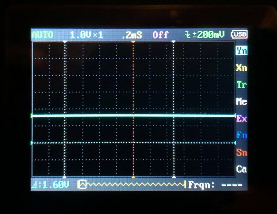
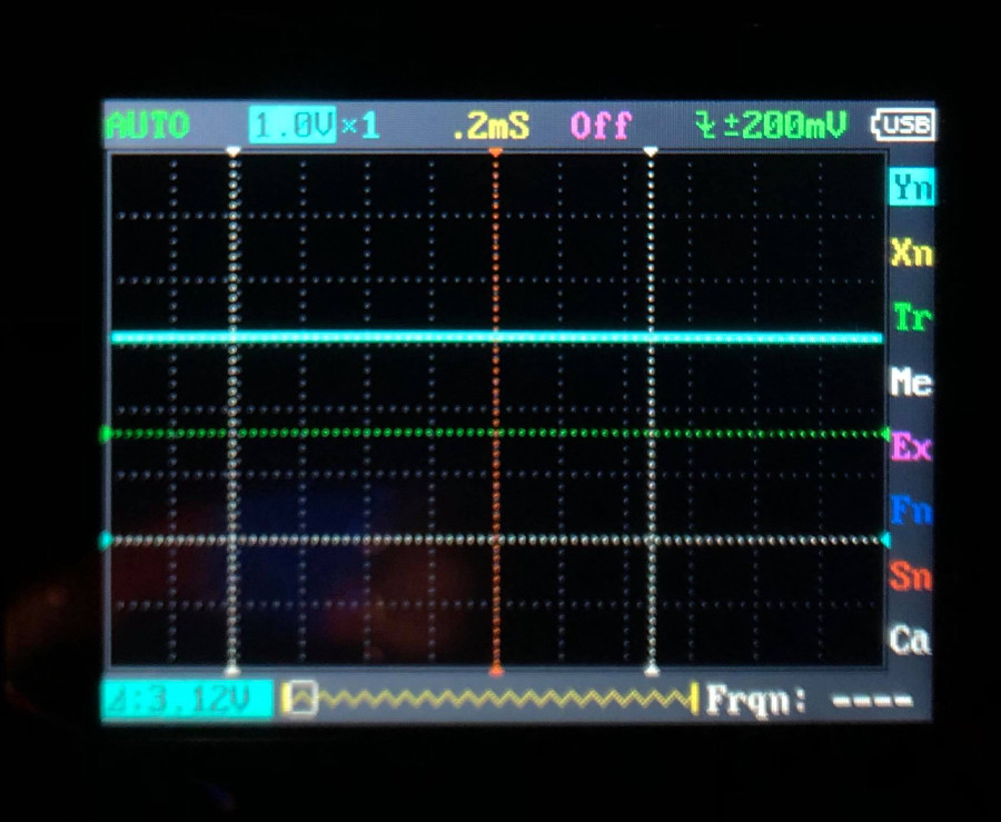
I also used the oscilloscope to measure the voltage of the red LED. They were measured using the 3.3V setting for the board. You can see the voltage measured in the blue text on the bottom left. First, measuring ground to ground: