This week's assignment was: add an output device to a microcontroller board you've designed,
and program it to do something.
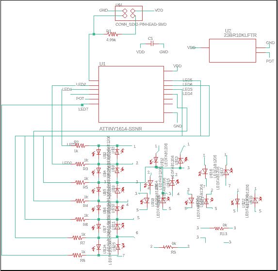
I decided to make a charlieplexed LED array this week to help work towards my final project. I looked up charlieplexing on wikipedia and here's how i'd summarize it: for any two input pins, you can have 2 leds, one facing in each direction. Simple enough. I went to Eagle to make my schematic and board!
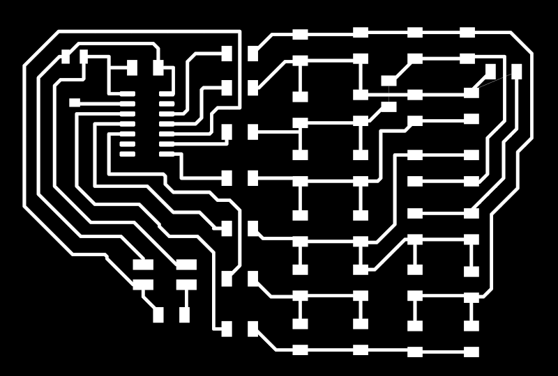
Then exported and opened in Inkscape to prepare the traces and outline:
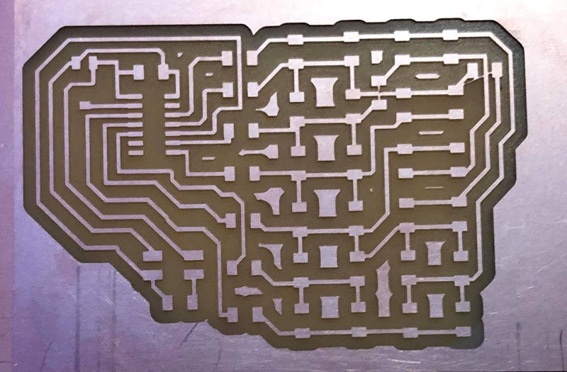
And then I cut out the board in the arch shops.
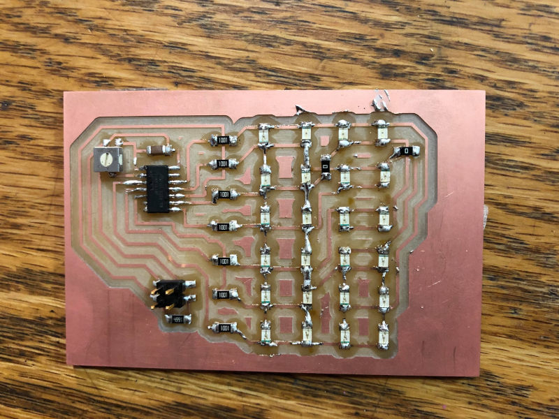
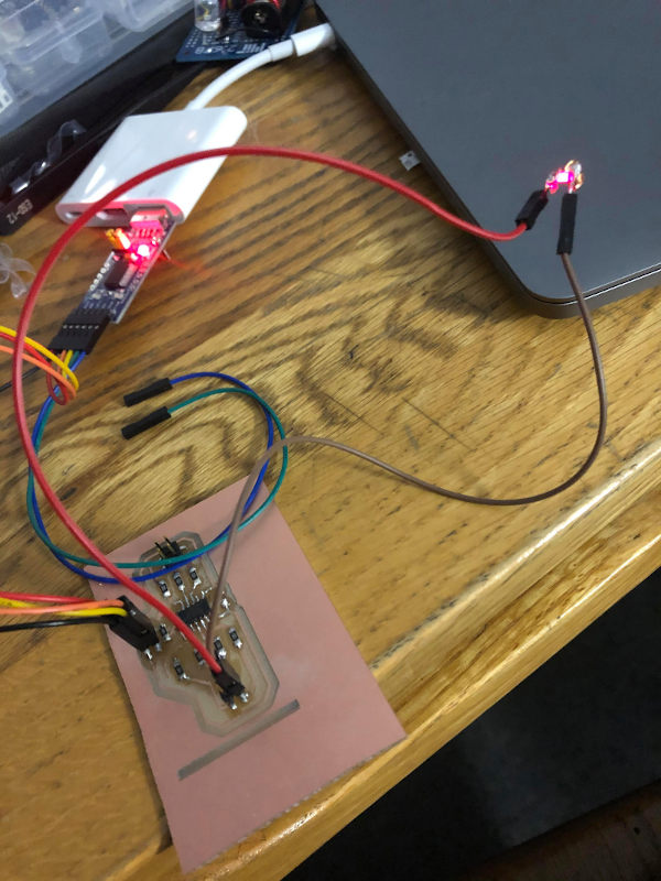
Then, I stuffed the board:
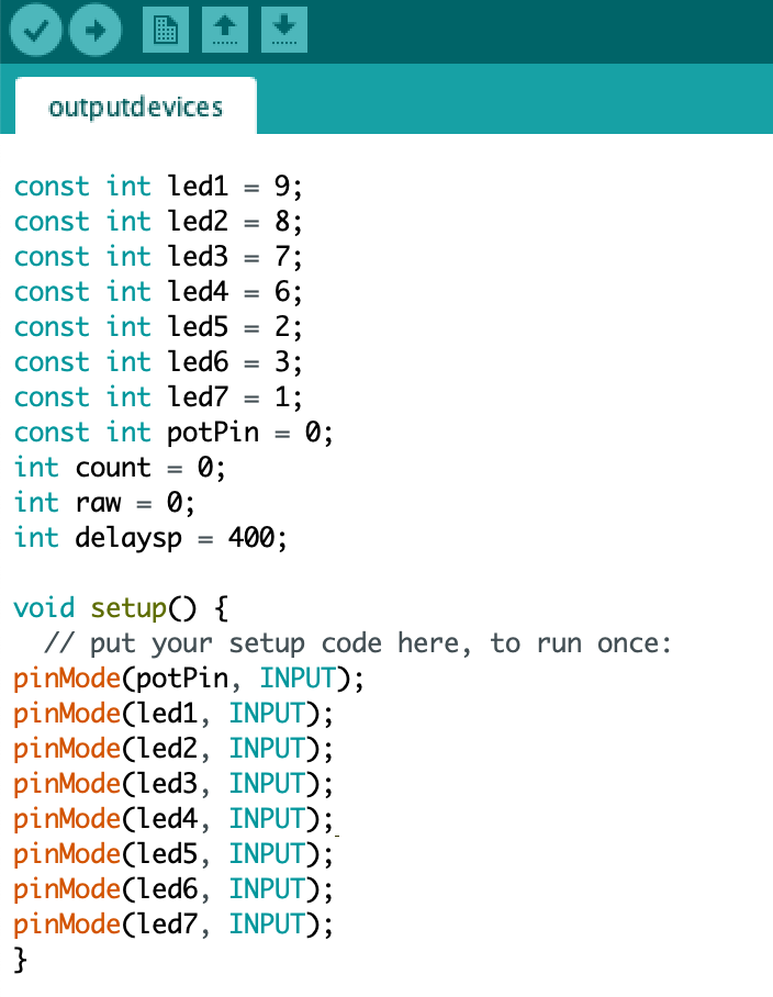
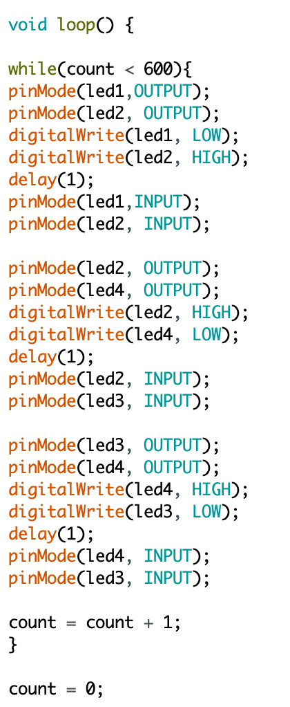
I programmed/uploaded the code to the board as described in previous weeks. I needed to use a couple code tricks to get things to work how I wanted. First, setting all the pins that aren't relevant to my target LED as input pins so that they aren't automatically set low and lit accidentally. Secondly, I wanted to be able to have specific LEDs lit at the same time. To do this I just had those target LEDs light really fast back and forth so that they all looked lit (delay of 1 microsecond). Here's the code for one example of lighting 3 target LEDs.
I repeated this code structure to create guitar chord shapes. Here's the board playing D, Dmaj7, Em, G, and A chords.
I also spent a lot of time this week trying some other materials to make boards out of. I tried lighting an LED with the copper tape that came in our kits and that went ok. I think it'll be a good backup plan once we're off campus:
I also vinyl cut a 6 led array to test out this method for my final project and programmed it similarly to what's shown above with an attiny3216 chip!