This week's assignment was: design, build, and connect wired or wireless node(s) with network or bus addresses.
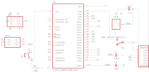
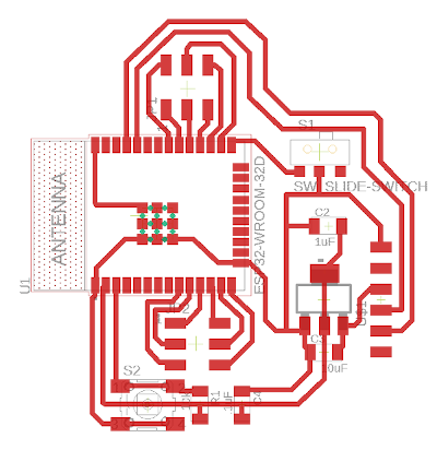
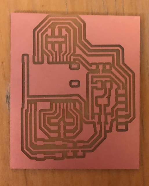
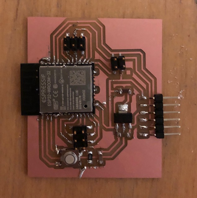
I've been planning to work with the esp32 board for my final project. I want to use wifi and a web interface for my final project, but since the esp32 board also has bluetooth, I wanted to try to get the bluetooth working this week! Here's my schematic and board designed in Eagle. I based it off of Neil's design, but added some headers to connect to the IO pins. I also replaced the switch with a 2x2 connector and was able to use the connector from serial adapter (for the 5v/3v) as the switch since one of my adapters broke earlier in the semester and I had two. I also had to edit the esp32 footprint traces a bit in inkscape to make the distance between them larger to be able to mill the board properly using clank. I also removed some of the extra footprints on the esp32 that I wasn't using. I used this soldering tutorial to solder the esp32. It worked really well! All of the pins on the esp32 that were connected to a wire were soldered down really easily. Some of the pins that didn't have any connections got a little lumpy and clumped together, but since I wasn't using them it wasn't a huge deal, but it did make the board look a little more messy. Overall, it worked! Here's the board making process:
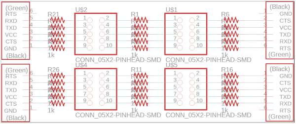
I also designed a breakout board with resistors so that I could wire the IO pins across these resistors and then to the LEDs on my final project.
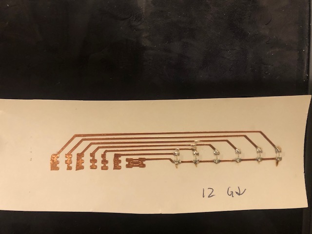
I then had the breakout board connecting to the LEDs on my final project. I used the vinyl cutter to cut copper and make the LED connections for each fret on the guitar. Each fret had one like this:
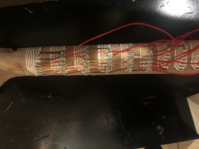
And the wiring was done on the back of the neck of the guitar like this:
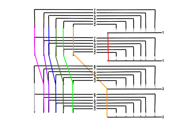
I cut and stripped some short wires to make the connections, and then realized using the copper sheet that I had left over from when I cutout my vinyl cut circuits was easier to use as connectors and the backing was enough of an insulator to just expose each end. I designed the LED fret board to require minimal IO pins while also being not too complicated to wire. This was the pattern I used to wire them:
I could use the same inputs two in a row by flipping the LEDs, then I shifted the inputs by one and added a new one. I repeated this pattern on the whole fretboard.
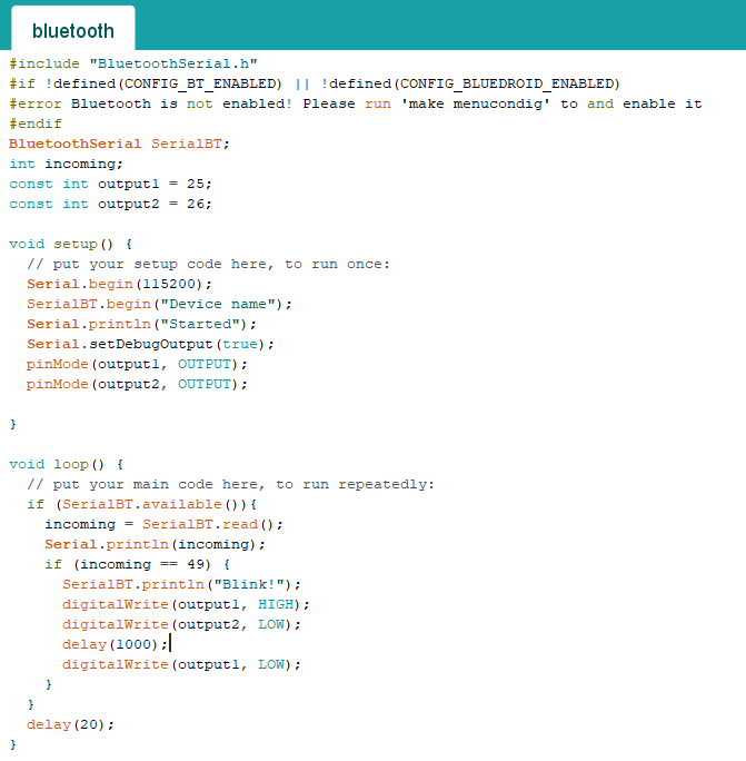
I went to Arduino to start programming. I decided to try to blink one of the lights on my final project over bluetooth through the Arduino serial monitor since once I can get one led working, I should be able to get them all working. Here's what the arduino code looks like:
I saw on Evan's site that he just checked the serial monitor directly for 49 since 49 is ascii for 1 (so you just need to type 1 into the serial monitor). One part of this that was a bit confusing was that I had to use one port for uploading the code and another for the serial monitor bluetooth. So just make sure you're always using the correct port and it should work out okay! Here's the bluetooth serial connection working and lighting an LED on my guitar. I typed '1' into the serial monitor, the led lights, and then the serial monitor writes 'Blink!'.