This week's assignment was: write an application that interfaces a user with an input &/or output device that you made.
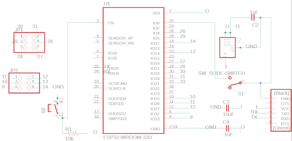
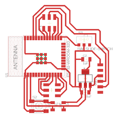
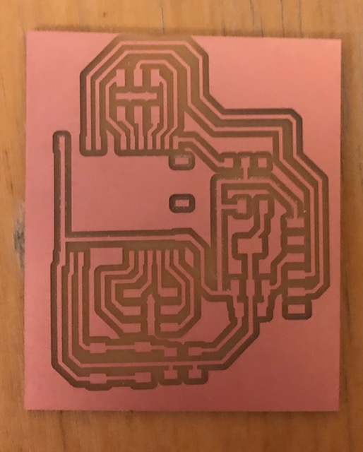
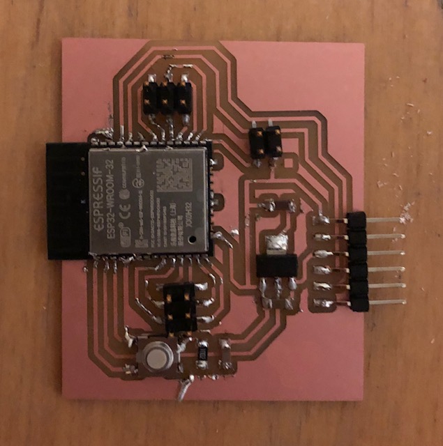
I wanted to continue to work with my esp32 board this week to use a web interface to interact with my final project! Here's my schematic and board designed in Eagle (same as last week). I based it off of Neil's design, but added some headers to connect to the IO pins. I also replaced the switch with a 2x2 connector and was able to use the connector from serial adapter (for the 5v/3v) as the switch since one of my adapters broke earlier in the semester and I had two. I also had to edit the esp32 footprint traces a bit in inkscape to make the distance between them larger to be able to mill the board properly using clank. I also removed some of the extra footprints on the esp32 that I wasn't using. I used this soldering tutorial to solder the esp32. It worked really well! All of the pins on the esp32 that were connected to a wire were soldered down really easily. Some of the pins that didn't have any connections got a little lumpy and clumped together, but since I wasn't using them it wasn't a huge deal, but it did make the board look a little more messy. Overall, it worked! Here's the board making process:
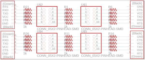
I also designed a breakout board with resistors so that I could wire the IO pins across these resistors and then to the LEDs on my final project.
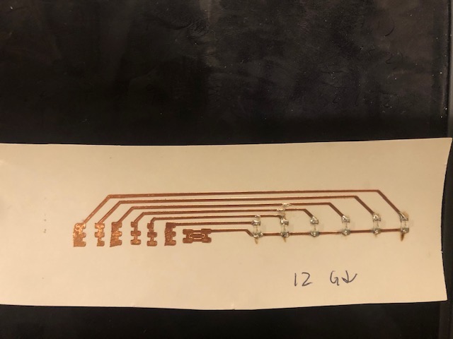
I then had the breakout board connecting to the LEDs on my final project. I used the vinyl cutter to cut copper and make the LED connections for each fret on the guitar. Each fret had one like this:
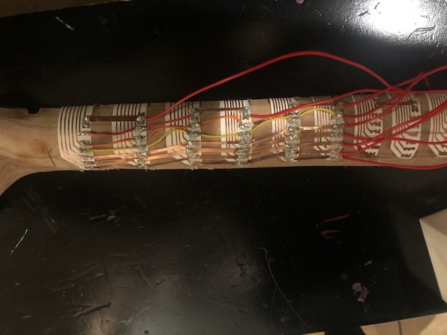
And the wiring was done on the back of the neck of the guitar like this:
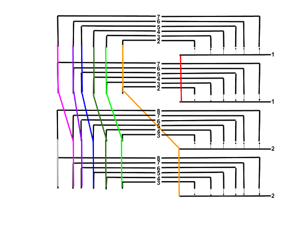
I cut and stripped some short wires to make the connections, and then realized using the copper sheet that I had left over from when I cutout my vinyl cut circuits was easier to use as connectors and the backing was enough of an insulator to just expose each end. I designed the LED fret board to require minimal IO pins while also being not too complicated to wire. This was the pattern I used to wire them:
I could use the same inputs two in a row by flipping the LEDs, then I shifted the inputs by one and added a new one. I repeated this pattern on the whole fretboard.
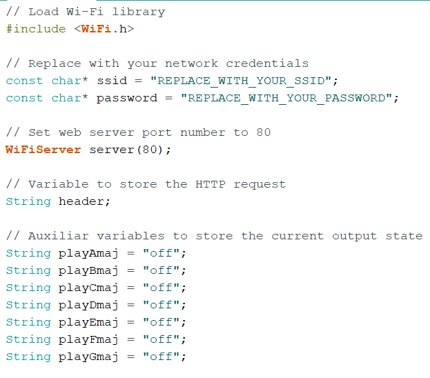
I followed this tutorial to get my esp32 connected to wifi and to set up a webpage to interact with it. It does a really good job documenting the code, and I really recommend checking it out if you're setting up a web interface! I'll input some snippets of my code, but it's pretty long, so I'll link it at the end as well. I didn't change the code from the tutorial that set up the interface and wifi connection, just the style of the webpage, added more buttons, and changed what the buttons did! Here's the beginning, declaring what you'll need:
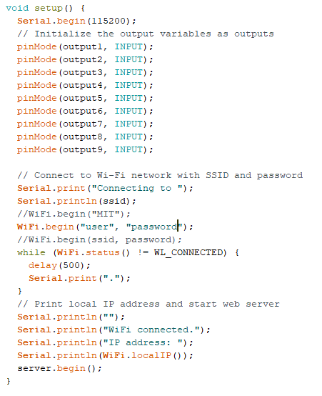
Then, the setup:
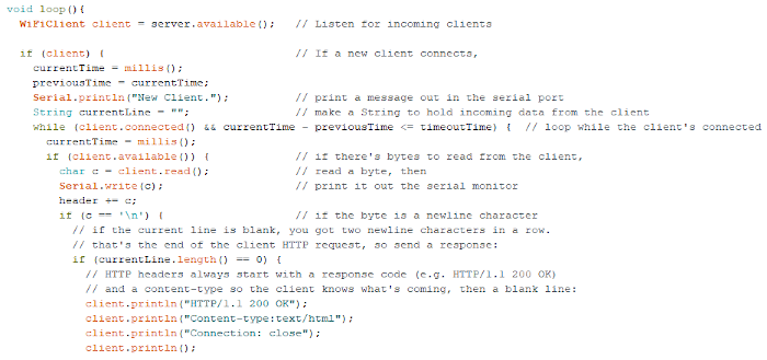
And the beginning of the loop:
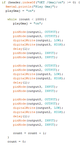
Here's an example of some changes I made. I checked if the message from the user in the web interface was to play a G major chord:
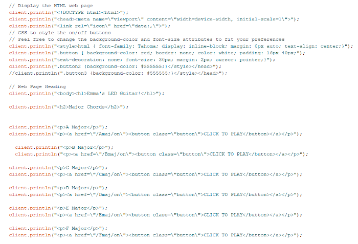
And setting up the web interface via the arduino code:
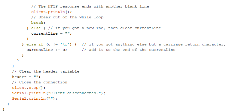
And the end of my code/loop:
After compiling and uploading the code onto my esp32, I could open the serial monitor to check what the webserver was and type it into my browser. Here's me controlling the guitar via a webpage on a phone: