The group assignment was: test runout, alignment, speeds, feeds, and toolpaths for your machine.
We first started by making a comb, like we did for the laser cutting characterization. Given that the CNC process can take a while, we decided to make it into a 2 step process:
1-Get a rough idea of what may or may not work using coarse increments (1mm) for the slots.
2-When we know which slot works best from round 1, go back and refine the increment.
So we made a fully parameterized model of the comb we will be working with. We were told that the OSB boards are about 0.44", but given that it can vary along the board, we figured
a fully parameterized model of the comb would come in handy.
This is a sketch of a single component:
This is the body of the comb after we extrude to the approcimate thickness of the board (0.44"):
Here is a list of all the parameters that can be changed:
This is something that caught us off guard. When doing the rectangular pattern, it was important to use the paramters "ToothWidth+SlotWidth" in the "Distance" field. Putting in a fixed
distance would cause any increase we make to the slot width to not show up because it would simply extrude further into neighboring bodies.
This is what we will use during our initial run:
This is an example of the comb after changing the SlotWidth paramter from 0.44" to 0.5":
CAM Setup
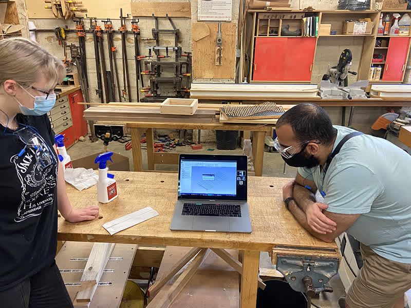
With the CAD file complete, it was time to learn how to set up the CAM file. Unfortunately, in the N51 Arch Shopt, the computer used for MasterCAM sits in a room that has a capacity of 1 person.
So we had to get creative. Zain zoomed us from inside the room and we watched from a laptop in the shop as he demonstrated how to set up our toolpaths:
The CNC cutter bit will always leave a slight radius on interior corners if we do not create a dogbone patter. As our comb has interior corners, we needed to create those dogbones. We therefore created a layer with points at each corner in Rhino.
Zain showed us how to use Grasshopper to automatically add points to the entire layout. This was fairly efficient for this model, but we still had to manually delete the exterior corners. Once those points were set, we could create two separate
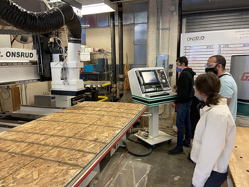
operations for the machine, one for drilling the points and one for cutting along the exterior lines. 1/4" and 3/8" bits respectively. Here you can see us getting ready to watch the Onsrad cut:
Onsrad Operating:
Operation 1: Drill Test
Operation 2: Bit Change
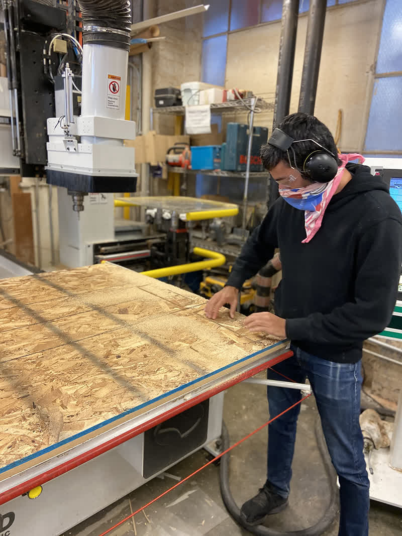
Operation 3: Cutting
Post Processing:
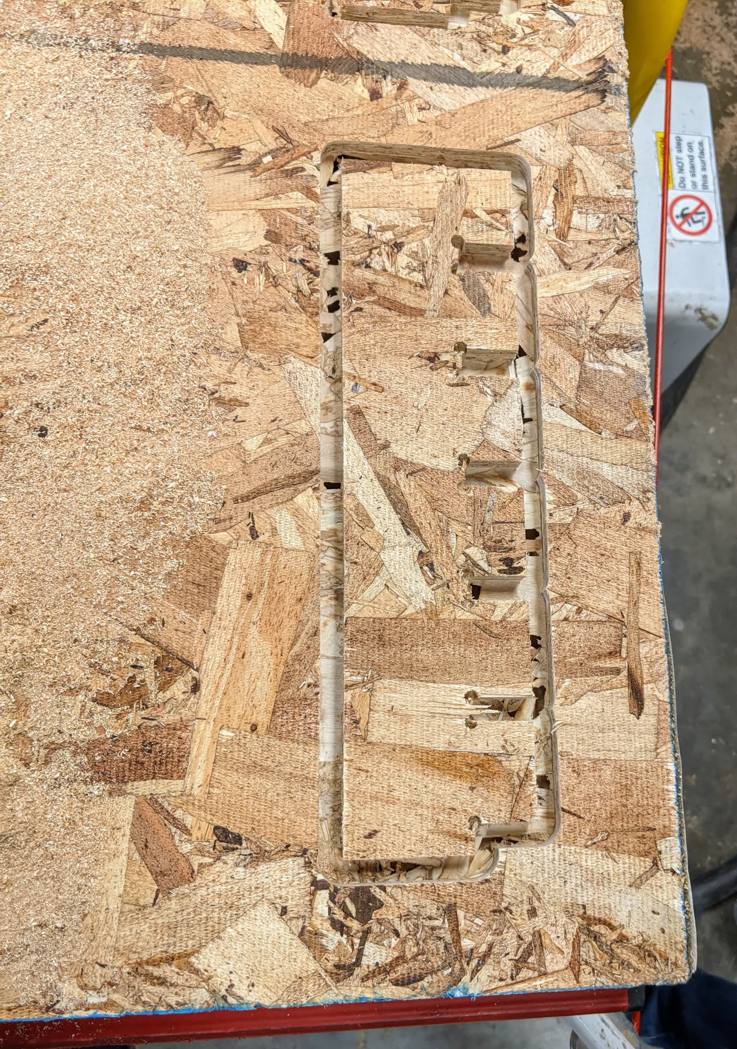
Successful cut. We left an onion skin to maintain a vacuum seal:
Removing the pieces from the bed:
Removing the pieces from the bed:
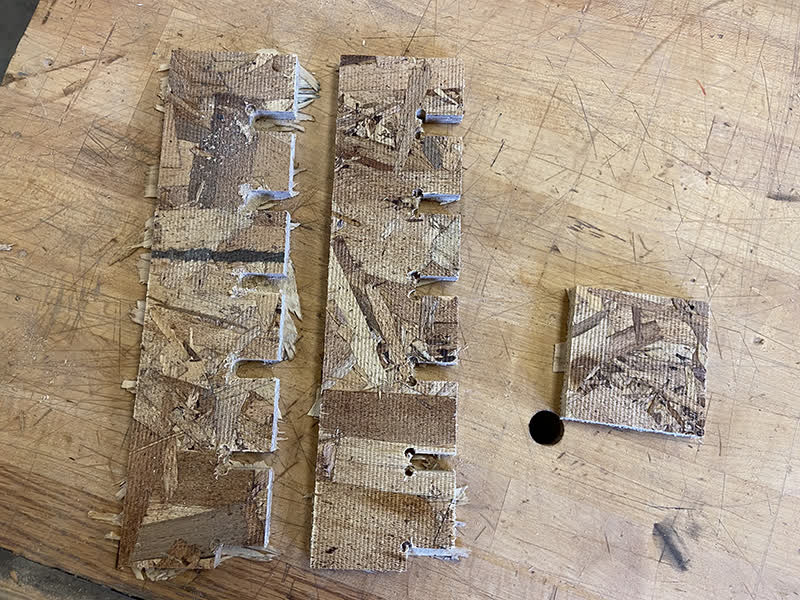
After clearing off the residual onion skin material, we measured each slot and measured its nominal parameter change:
Testing the joints, we found that our best fit was 0.46" -lmm. This left us with roughly 0.42", but we recognize that this measurement would is not indicative
of the thickness of another piece of OSB. It worked for this piece, but we learned that each piece should be measured prior to cutting and that each model should
parameterized to allow for adjustment of the material thickness:
 This is the body of the comb after we extrude to the approcimate thickness of the board (0.44"):
 Here is a list of all the parameters that can be changed:
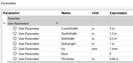 This is something that caught us off guard. When doing the rectangular pattern, it was important to use the paramters "ToothWidth+SlotWidth" in the "Distance" field. Putting in a fixed
distance would cause any increase we make to the slot width to not show up because it would simply extrude further into neighboring bodies.
This is something that caught us off guard. When doing the rectangular pattern, it was important to use the paramters "ToothWidth+SlotWidth" in the "Distance" field. Putting in a fixed
distance would cause any increase we make to the slot width to not show up because it would simply extrude further into neighboring bodies.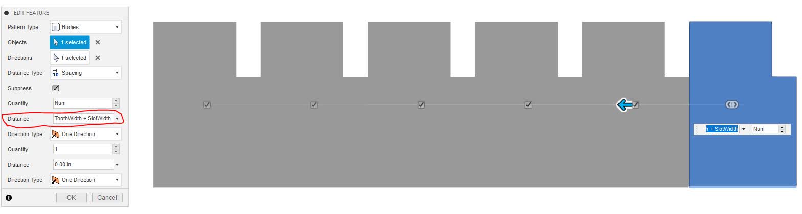 This is what we will use during our initial run:
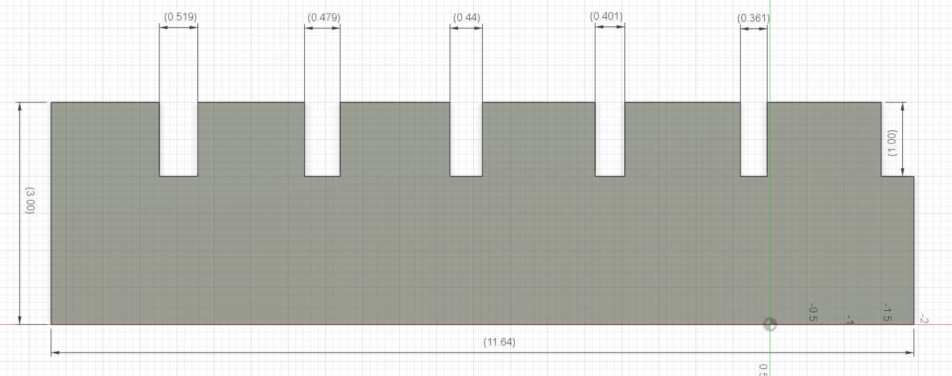 This is an example of the comb after changing the SlotWidth paramter from 0.44" to 0.5":
 The CNC cutter bit will always leave a slight radius on interior corners if we do not create a dogbone patter. As our comb has interior corners, we needed to create those dogbones. We therefore created a layer with points at each corner in Rhino.
Zain showed us how to use Grasshopper to automatically add points to the entire layout. This was fairly efficient for this model, but we still had to manually delete the exterior corners. Once those points were set, we could create two separate
operations for the machine, one for drilling the points and one for cutting along the exterior lines. 1/4" and 3/8" bits respectively. Here you can see us getting ready to watch the Onsrad cut:
The CNC cutter bit will always leave a slight radius on interior corners if we do not create a dogbone patter. As our comb has interior corners, we needed to create those dogbones. We therefore created a layer with points at each corner in Rhino.
Zain showed us how to use Grasshopper to automatically add points to the entire layout. This was fairly efficient for this model, but we still had to manually delete the exterior corners. Once those points were set, we could create two separate
operations for the machine, one for drilling the points and one for cutting along the exterior lines. 1/4" and 3/8" bits respectively. Here you can see us getting ready to watch the Onsrad cut: