Final Project
Senspheres
Distributed sensing and networking for space mapping. Senspheres are tiny balls with sensors and RF communication. The basic idea of the project is using them within different use cases for mapping states at the room, building and city scale. The sensors can be thrown around for easy deploymnt and their design allows for modular used of the devices. The current version is capable of creating a star network for data collection of temperature and light states.
Click to start video.
Energy Harnessing Ball - First Concept
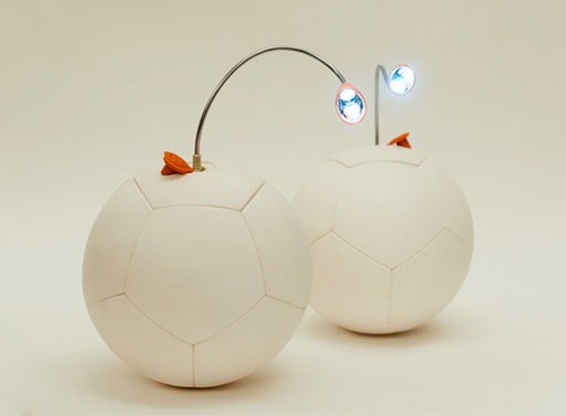
Thinking about what to build when you have the option to build (almost) anything can be overwhelming. I decided to take a look at my idea and project bucket list to get some inspiration and ideas. I came back to a concept that I had worked on the "Settlements Without" course taught by the City Science Group at the Media Lab. The idea was to create a ball that could potentially harness kinetic energy and turn it into electrical energy for later use. This concept could be relevant for communities that lack access to electricity. The ball would include built in LED's and a charging port so that it could be used as a lamp or a charging station when charged. Below is a concept ilustration.
I would aim for being able to make a device that can harness energy from different contexts and types of use. Movements could mainly be rotational or linear. In order to combine harnessing from rotation and linear translation, I though about piezo cantilevers. If placed, cleverly, you could harness ebergy from forces acting on multiple axis at a given time. The first concept includes a main strcuture that has an array of cantilever piezos attached to it. The storage unit would be at the center of the structure and the plug would be located at one of the structure axis in order for it to be accessible from the outside.
As suggested by my professor, I thought about changing the harnessing mechanism from a piezoelectric array into a pendulum based mechanism. This would allow for more efficient conversion of rotational forces. As I was thinking about how to expand the harnessing capabilities, I looked into the project that I did for W2 - 3D printing and Scaning. Which is shown below. It was a gyroscope style mechanical device that allowed for multiple degrees of freedom depending on its orientation. I though this could be a good way to make sure that the pendulum and generator are always alligned for optimal energy harvesting.
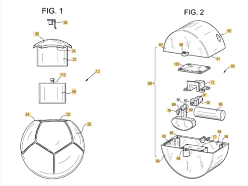
As I was exploring the idea a bit further, I realized that it has been previusly done by a pair of Harvard students and that it had already been spun out as a company back in the early 2010's. The project is no longer available but they do have a patent that is very similar to the system I was thinking to build. If it has already been made, has a patent and already failed as a start up, I think that I could invest my time in doing something more novel. So I went back into brainstorming mode to pivot my first idea.
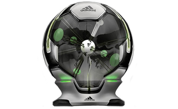
As I was thinking about different possible outcomes for my final project I passed through the idea of keeping the idea of the ball and changing energy generation to sensors. I came across a ball designed by Adidas (shown below) that has a very interesting design to intergrate force sesnors and accelerometers into a "playable" ball. I do like the idea of having sensors embedded within spheres so I expanded a little on what a different concept could look like. Its a bit late in the semester to still be pivoting with ideas but I think that defining an exciting project is crucial and timing still allows me to pivot around.
After some analysis and feedback from instructors I have come to a final concept for my project...
Sensor Spheres!
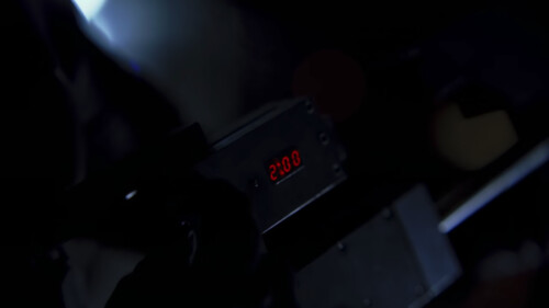
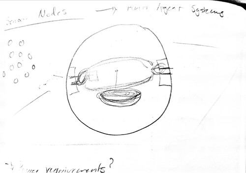
I've had an idea of creating sensor nodes that are embeded into spheres for a while now. The main concept is to embed different types of sensors into spherical nodes that can later be easily distributed and connected within a space. You would hava a main node that would act as the central data collector and small peripheral spheres that could be thrown into a space in order to sense different variables. The system takes inspiration from several places in the back of my mind. First, I have always been a fan of exploration robots that can be deployed in order to sense specific variables at a given situation. Some of this inspiration has been influences by the likes of the spider robots from Minority Report and plenty other scifi references. The second characteristic of the sensor nodes is inspired by the latest Batman Trilogy. Specifically, on the second movie (probably the best of the three), there is a scene where Batman uses a gun to shoot timers that contain explosives into the sides of a building. There is something magical about throwing, shooting active electronics around. I will not be making them explosive though.
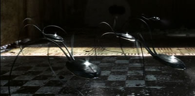
This are the small modules that Batman shoots in Hong Kong!

And this is the gun that he uses to program them and shoot them.
With that in mind, I decided to start working on the design for my project. Looking back into my previuos assignments, I realized that some of them would be very useful for implementing my idea. First off, I started doing some sketches. Sketches usually help me to give form to an idea, understand the physical implications that it has and to foresee possible difficulties that building it might bring. Thi sis the first rough sketch of the sensor sphere. I'm thinking of using a pendulum mechanism within the device in order to always have my sensor board facing up. This is important for some sensors such as light and maybe even for ones that have to be in direct contact with the environment like pressure, humidity or temperature. The pendulum will make throwing the devices feel a bit unbalanced but it should be ok.
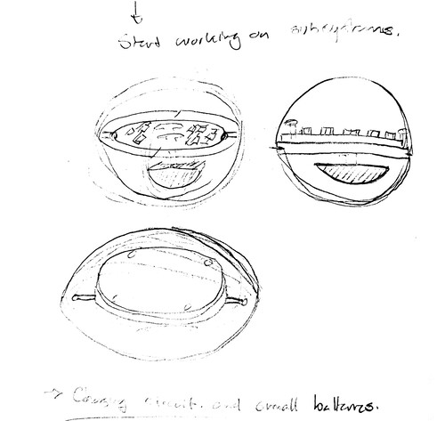
While thinking about the design of the modules, I realized that some of the weekle activities have explores aspects that I will need for building these modules. On the 3D printing week, I explored the design of gyroscopic mechanisms. This will be useful in order to build the mechanism that will orient the sensor board as explained above.
I am still unsure about the manufacturing process for the external shells. I am unsure if 3D printing or casting will be the way to go. I'll define the process once I have a better representation of what I need for the shells to fucntion properly...
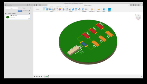
I started experimenting with the creation of round circuit boards and with the integration of boards from EAGLE to Fusion 360. This will allow me to create a design that is well built around my boards which will be the central element of the spheres.
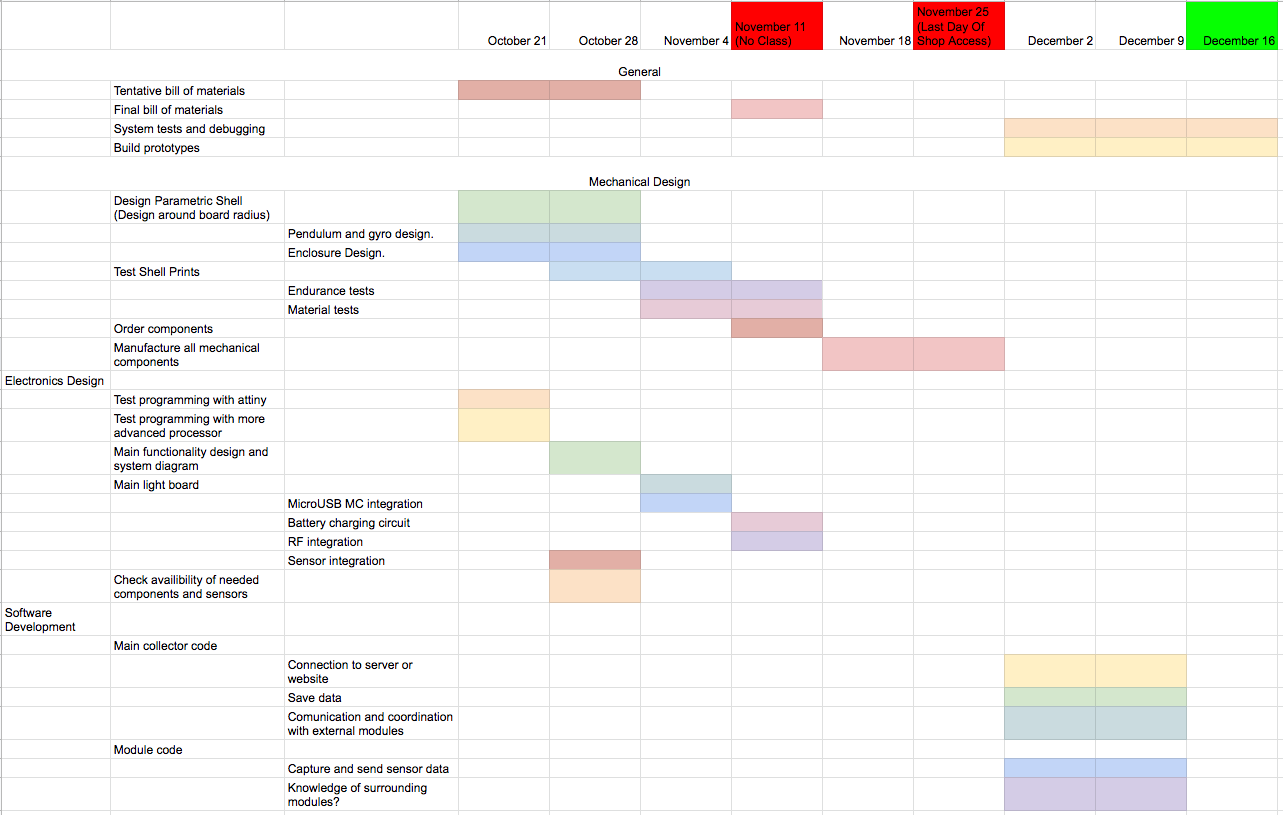
We are currently in the middle of week 7. It is the perfect time to create a strict schedule to outline major steps that have to be taken in order to omplete the final project. I have divided activities within a simple Gantt model. At first, mechanical deisgn will be the major load, due to the pandemic, shop access will be limited so getting mechanical designs and pieces ready before Thanksgiving is crucial. My prototype will have a larger load on the electronics aspect but I still have to get the mechanical side working in time. I will start alligning all of my electronics work with the criucial circuits and board designs that I need for my final project. Weekly assignments for inputs and outputs will be closeley tied with my final project. Finally, software development will be done towards the last weeks of the course. No shop access means that I should have prototypes ready to be programmed and tested a week after Thanksgiving. You can find details of my planning below:
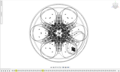
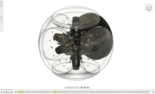
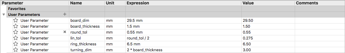
I started testing some mechanisms to mount the boards into the spheres. I'm looking into using a gyroscopic deisgn to allow my board to always be facing upward. This is importante because that will allow me to get more reliable readings from the sensors. A good example is light. If I throw the sphere and it lands in a way that the light sensor is facing downward, I will not be able to see relative differences between nodes due to the fact that they are not facing the same plane. I tested some of the tolerances that we specified on the first week. I created a new gyro design, the design is 100% parametric, this will allow me to adjust it easily in terms of changes that I make to my board design along the way. My future self will thank me for this.
I found that the best way to cosntruct the pieze was by doing a single sketch of what the center section would look like. This allowed me to the use the different goemetries from the same sketch to revolve and extrude the components.
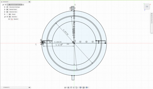
You can find the model below:
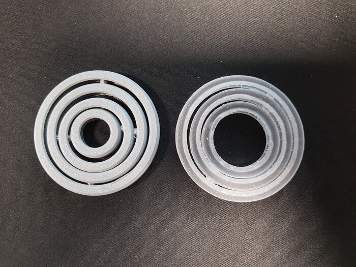
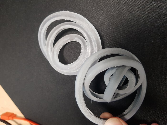
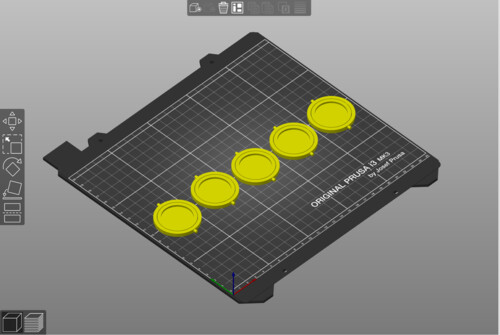
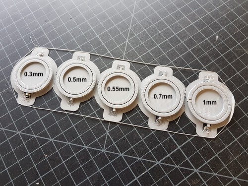
I the proceeded to print out some tests with different tolerance values. [.3mm .5mm .55mm .7mm 1mm]
The prints came out great and I believe that I will be using the .55 or .7 tolerance for my design. It allows for a stable but free mechansim.
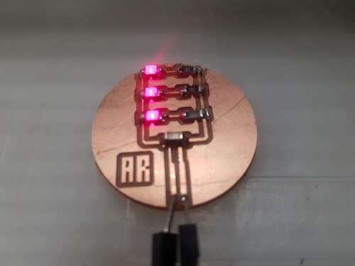
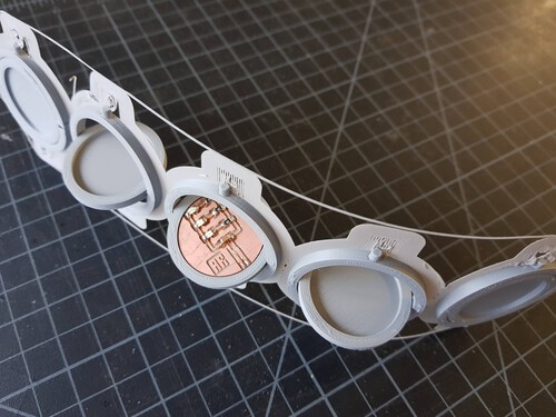
My test board also fit neatly inside of the design!
I've started making my tests for the outer shell and inner gyro. I used the stl model that can be found above and the led board that I build a couple of weeks ago. My print worked well but my design needs some improvements. The board fits well, the gyto can spin properly but my counterweight design does not allow for the gyro to spin so I will get rid of that section of the model. That was a very silly mistake.
I've started making my tests for the outer shell and inner gyro. I used the stl model that can be found above and the led board that I build a couple of weeks ago. My print worked well but my design needs some improvements. The board fits well, the gyto can spin properly but my counterweight design does not allow for the gyro to spin so I will get rid of that section of the model. That was a very silly mistake. The structure survived my throwing tests well.
I'm also staring to develop tha boards that will be going inside of the sphere. This week, I worked on a temperature board. I got the dimensions correct but I still need to add components to it so I will need to improve my design. I will also have to figure out how I will manage batteries.
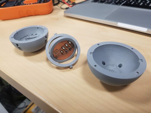
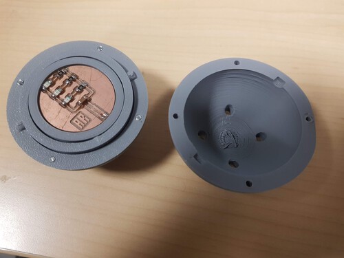
After the results from the first sphere design, the one with an internal gyro, I decided to iterate into another way of maintining my boards orientatin facing upward. The gyro design made the did not spin very fleuntly and it made it hard to make the sphere smaller. I decided to use different printing densitites on a split sphere. By doing this, I shift the center of gravity toward the buttom half and my spheres always balance into position. Here is my new design. This deisgn allows for smaller dimensions of the overall sphere.
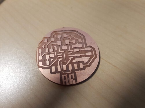
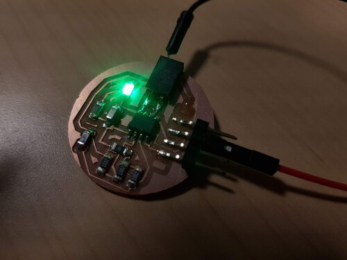
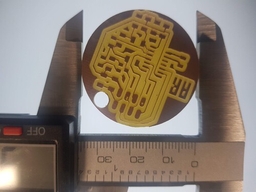
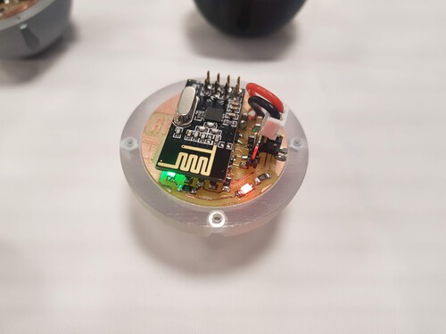
I've also been developing the first sensor board for the spheres. The sensor board is a temperature sensor board with a built in RF transmitter. I will be working on a version that has an LED for signaling operation of the board. I am planning to use a 40mhA lipo battery to power my electronics. They will not last long but it should be good enough for the first tests. Design and milling went well.
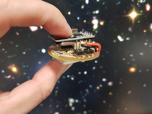
And here is the board with all the components soldered on and the battery attached to the back of it. Size is looking promising with the constraints that we have with our millinf machine and package size for the components available at the lab.
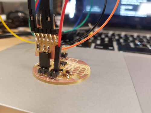
I managed to program it with the following code. The code only calculates temperature in Celcius and sends it over RF. The board is using the simple NRF240 Radio module.
      ////Sen-Sphere Temperature MARKI

      #include
      #include
      #include
      #include
      #include

      RF24 radio(1, 0);

      int refPin = 6;
      int ntcPin = 7;

      const byte addresses [][6] = {"10911", "10917"}; // MSN, MSG

      void setup() {

        Serial.begin(115200);

        pinMode(refPin, INPUT);
        pinMode(ntcPin, INPUT);

        Serial.println("Starting Up Radio!");
        radio.begin();
        radio.openWritingPipe(addresses[1]);
        radio.openReadingPipe(1, addresses[0]);
        radio.setPALevel(RF24_PA_MIN);
        radio.startListening();
        Serial.println("Radio has been started!");

        Serial.println("Ready to begin!");

      }

      void loop() {
        // put your main code here, to run repeatedly:
        Serial.print("Temperature is: ");
        Serial.println(read_temp());
        send_rf_data(read_temp());
        delay(500);
        Serial.println("Sent New Data!");

      }

      float read_temp() {

        float Vref = analogRead(refPin);  //Reference Voltage.
        float Vntc = analogRead(ntcPin);  //Tension on NTC.

        float Intc = ((2*Vref) - Vntc) / 10000;

        float Rntc = Vntc / Intc;  //NTC Resistance Calculation.

        float Tk = 1 / ((log(Rntc / 10000) / 3750) + (1 / 298.15)); //Scale resistance to temperature in kelvin.

        float Tc = Tk - 273.15;  //Convert from Kelvin to Celsius.

        return Tc;

      }

      void send_rf_data(float message) { //Function sends a command via radio. Takes string as argument and converts to char to send.

        //char mess[4] = "000";
        char temperatureValue[8];
        dtostrf(message, 6, 2, temperatureValue);
        //strcpy(mess, message.c_str());
        Serial.println(temperatureValue);
        radio.stopListening();
        radio.write(&temperatureValue, sizeof(temperatureValue));

      }
The sensor is working properly and radio is commmunicating well!
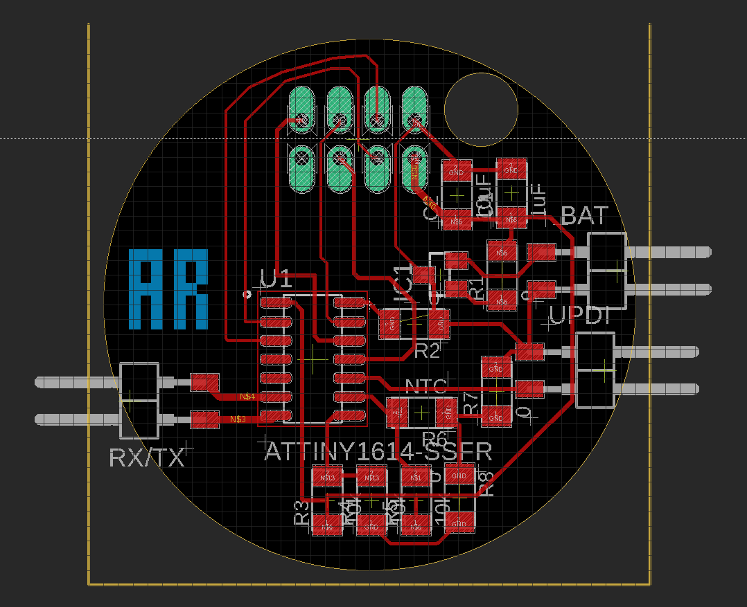
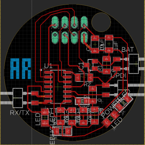
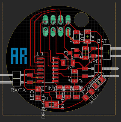
I decided to make some fies to the previous board design in order to get more capabilities onto it. I've decided to add two led's onto the board. One is just for indicating that the board is powered and the other one is for debugging. As I will be having many nodes, it will be easier to know what each node is doing through flashing an LED. The new version uses a smaller package (0805) NTC resistor as well. I was able to get much better tracing with the new design. You can see my new design below. This will be my basic design. I will try to build boards with different sensors and fit them into the same form.
As a first test I used an old device that was NRF enabled to test my boards. The first program was just to see if the board were working properly. The new board would send a message to the olf board and change the color of the LED. Below is a video. i encased the board and powered it by battery in order to test the electronics and mechanical design working together. You can see that the balancing mechanism also works and it makes it seem like the little sphere has a life of its own.
Click to start video.
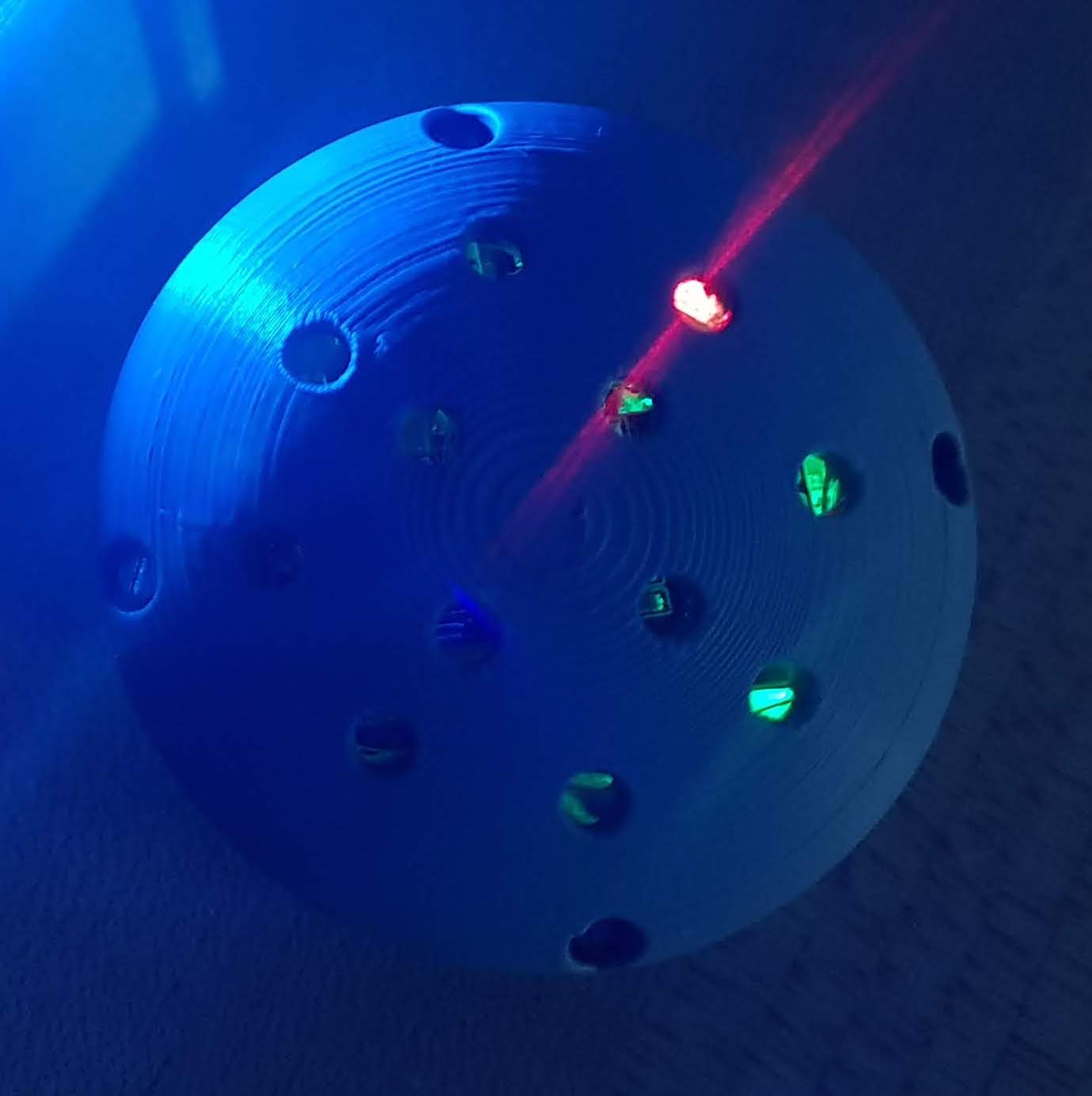
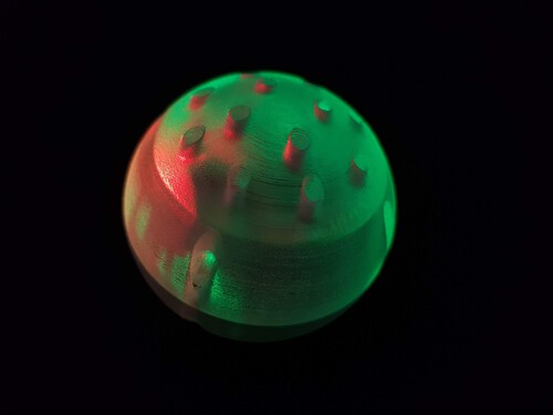
And here is the node flashing on its own. The green LED flashes everytime a data packet is sent through the RF chip.
Click to start video.
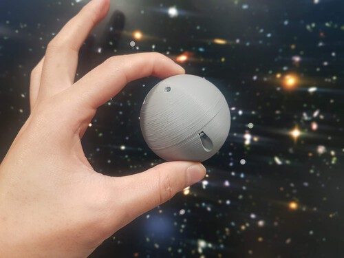
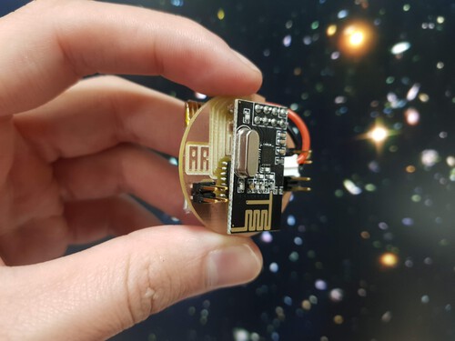
And here is an image of the device. I also tried rolling it around and throwing it to test its resistance. There seems to be room for improvement but it is quite robust as of now.
I've also started making the nodes talk to each other. A goood challenge will be coordinating communication when I start to add more nodes to the system. For now, I have built two simple codes for testing the devices as receivers and transmitters. In the demo below, one of the devices transmits its ID and temperature data to the other. the receiver prints the data through serial to my computer terminal.
Click to start video.
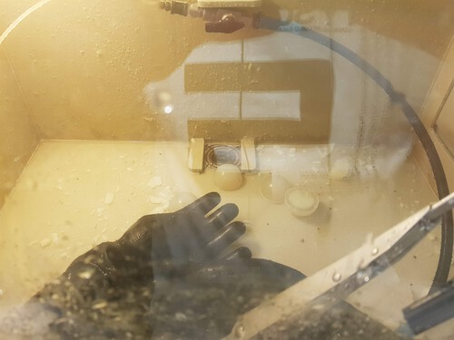
I have begun to ramp up production process for the final versions of my boards and spheres. In order to try out different materials and printers, I printed out several models on the Prusa dn on the Startasys printers. The model fits well with my boards and the mechanics seem to be working perfectly. I think I can improve upon the aesthetics of the design but the current version will do well for the class project. I had not used the Startasys printer as much so I documented a bit od the process.
Click to start video.
After the print, the pieces come out surrounded by the support wax. I used highly pressurized water inside a chamber to clean them.
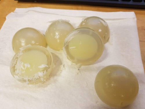
And here is the final result with the first temperature board version that I made.
I have also made the first trhwowing test. Its great to see that the materials hold, the board is thightened up properly and it self balances to make the top of the board always face upward! Enjoy the video.
Click to start video.
After checking that my mechanical design and that my basic electronic design work, I have moved on to create a light sensor board. The idea will be to have the same basic model carry different boards inside. For the final project I will be experimenting with having temperature and light boards. I have designed the new light board based on a visible light phototransistor.
During production of the light board I ran into several issued with my clank. My boards were not coming out fine at all. I decided to dissasemble it, tighten everything properly, clean the bearings and change to new bits. Doing all of this helped me solve the problems.
After dealing with clank issues I was able to ramp up production of boards. I currently have 3 light boards and three temperature boards talking to eachother!
And here is the family talking to eachother!
Click to start video.
I used my final weeks to work on interfacing and networking with the nodes. i used python to create a serial port that talks to the receiving node. All of the processing is done by two scripts. One is used to organize the data, to monitor the network and to save the information coming from the netwrok. The other can visualize the node topology in 2D and 3D.
Click to start video.
And here is the final video documenting all of the steps an chaos that went into the creation of senspheres! Enjoy!
Click to start video.