W1 - Computer-Controlled Cutting
Assignments:
- Cut Parametric Construction Kit (Laser Cutter)
- Characterize 30W Laser Cutter
- Use The Vynil Cutter
Laser Cutter
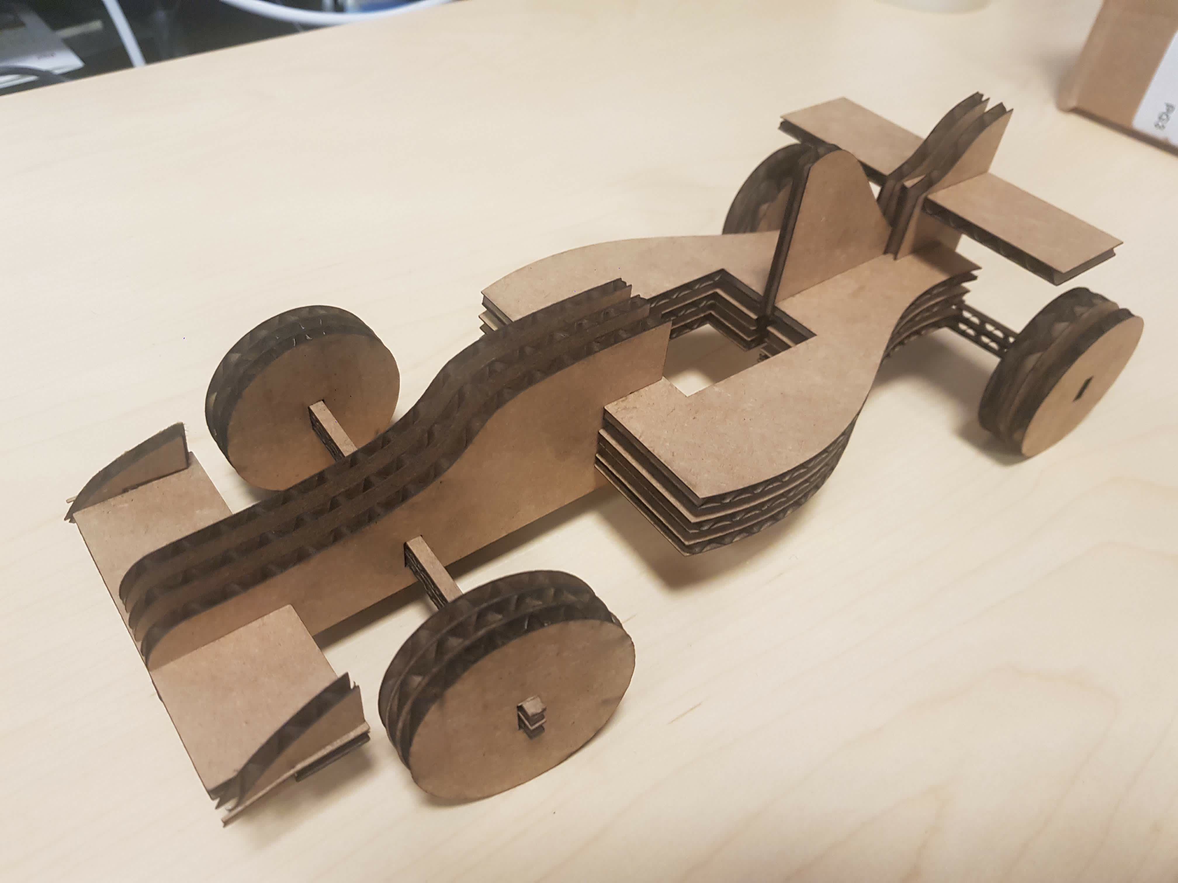
I designed a Formula 1 parametric construction kit. The kit was designed in Fusion 360, exported as DXF and cut on a 30W Laser cutter.
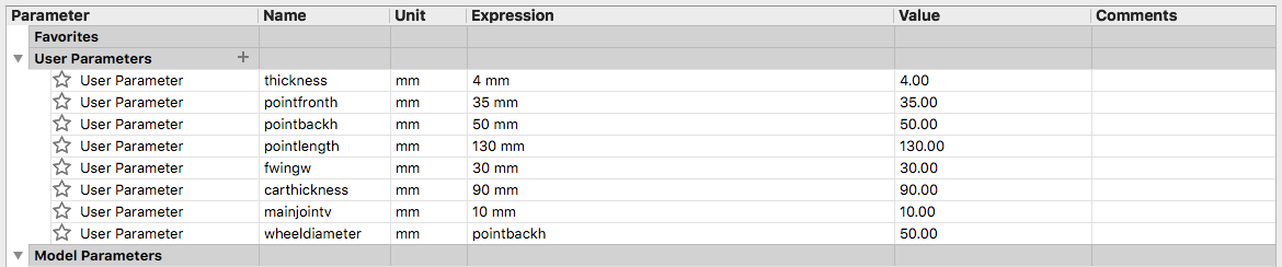
I first defined parameters to be used within my design. I based parameters and dimensions of the design so that every
dimension is mainly in terms of the cardboards thickness, the diameter of the weels and the main dimensions of the middle section.
Extra parameters were also added for designing different types of joint. It is relevant to mention that it is recommended to parametize
every dimension that is used in order to make redisgning, scaling and remixing free of warnings and bugs!
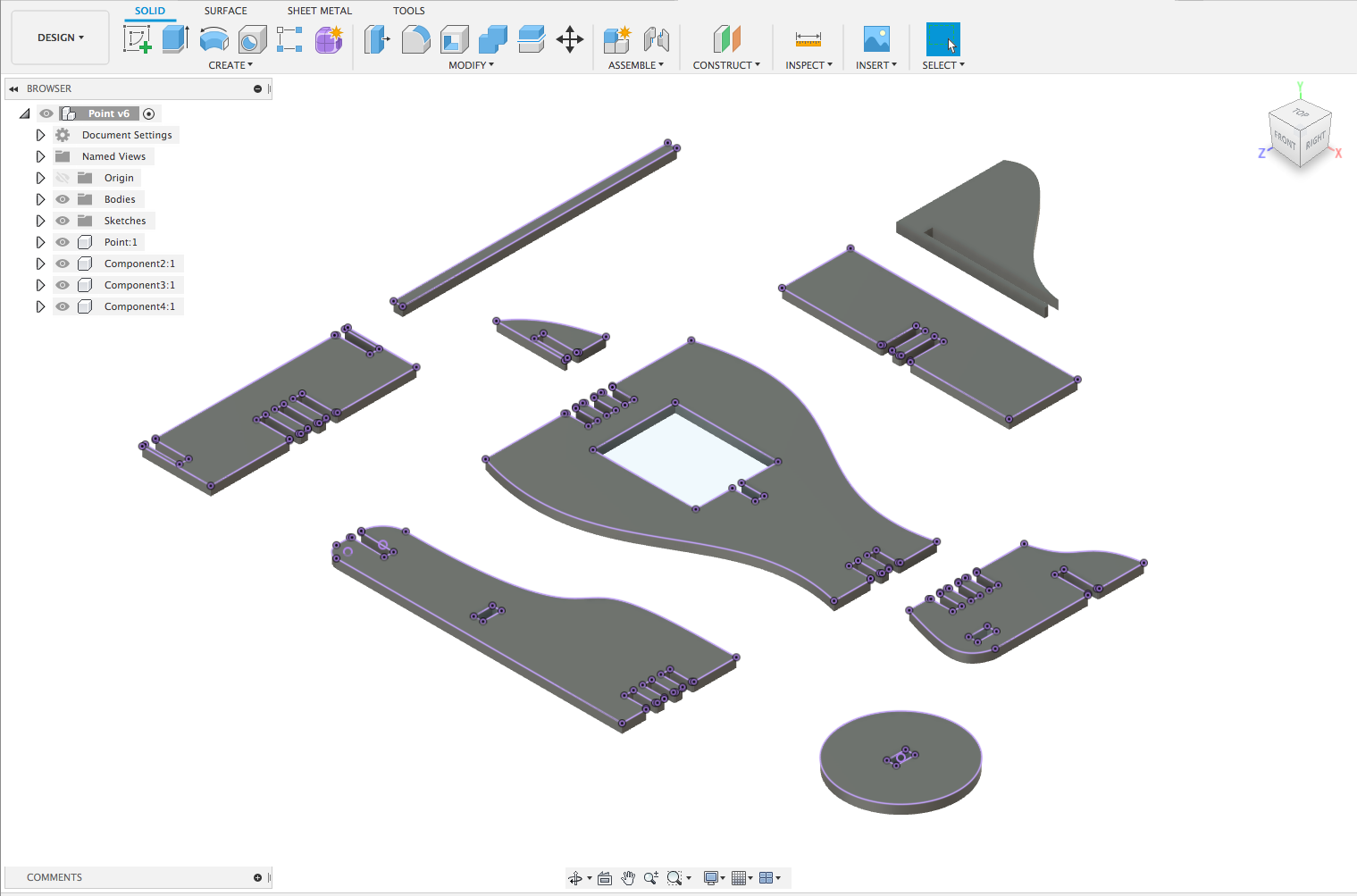
I sketched and extruded each piece on a single file within fusion. After all pieces were finished. I selected all faces and exported them as DXF.
Outlines that were exported appear in purple within the image.
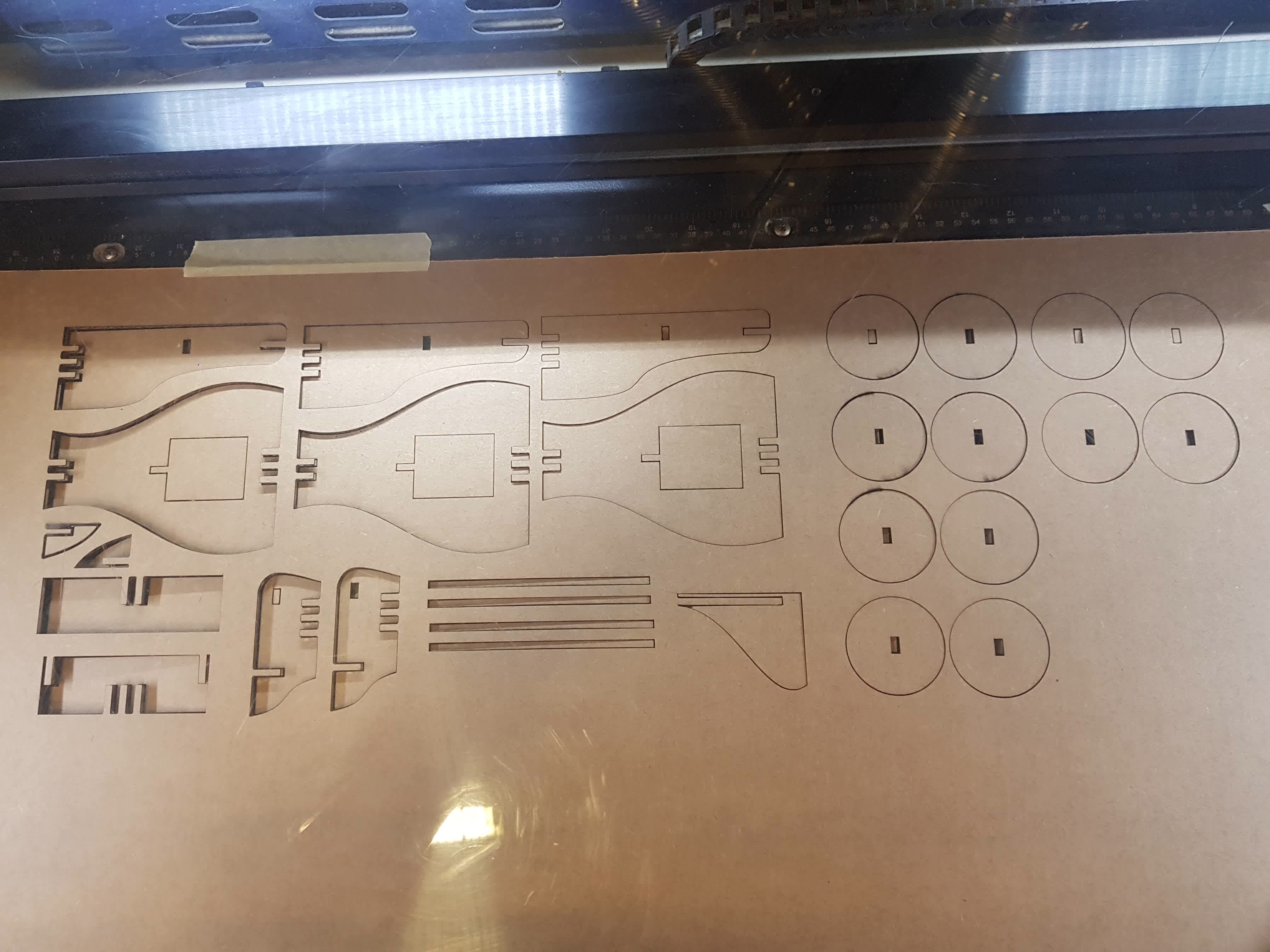
After individual pieces were exported, I created a new DXF file that contains all the required components as well as a good arrangement for minimizing material waste.
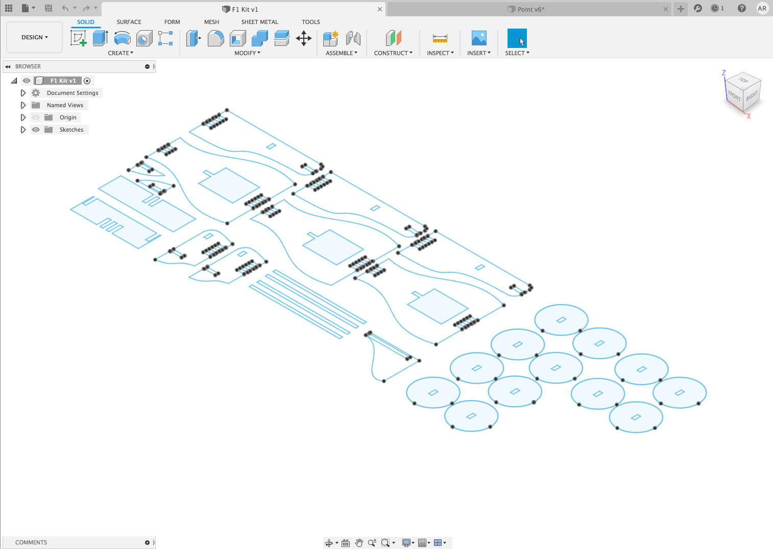
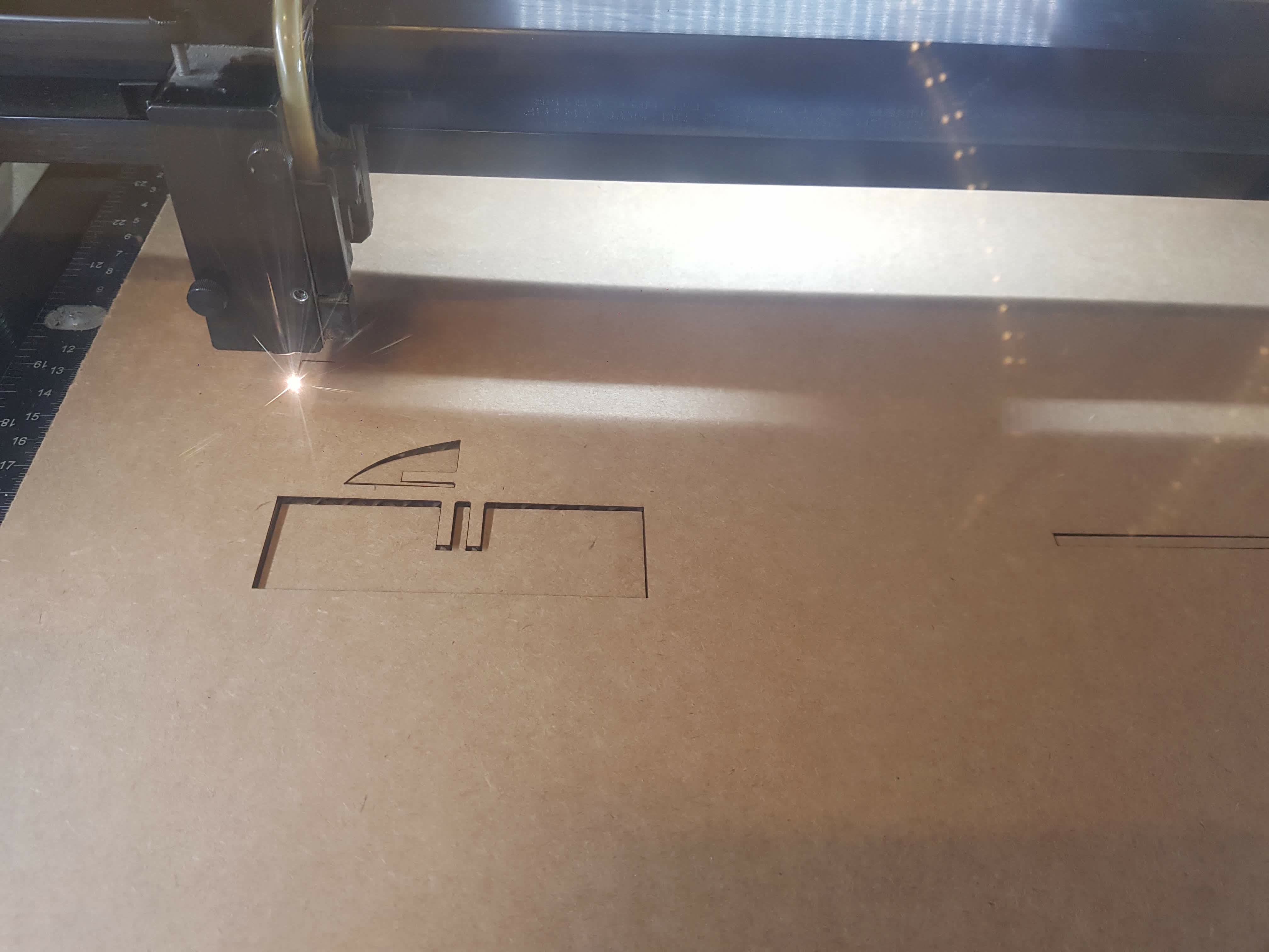
I sent this file to the laser cutter with print settings of Speed = .5 Power = 80 and PPI = 220. The cut took 13 minutes to complete. Result is shown below.
Finally, I assembled the pieces by hand! =) the construction kit worked!!!
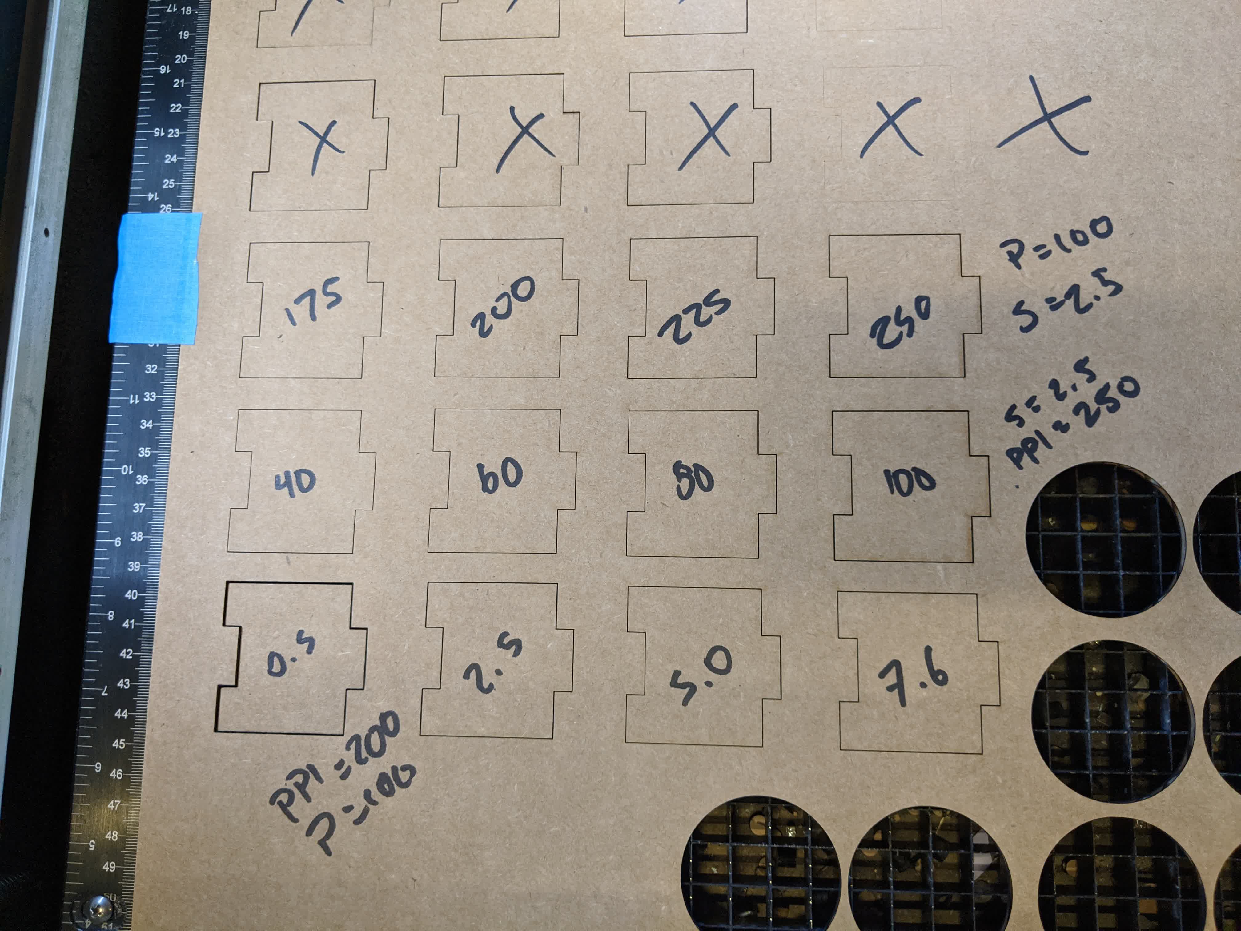
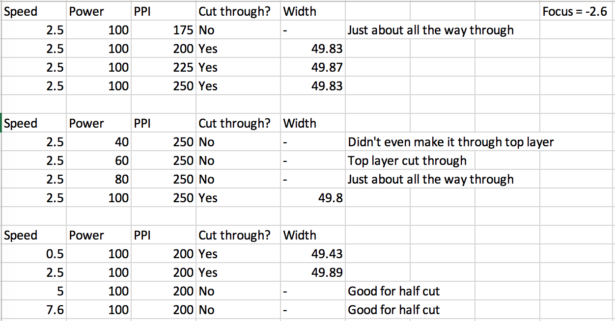
Our task was to characterize the laser cutter as a group. We carried out characterization of the 30W cutter using a 4mm think cardboard board.
In order to characterize the laser we carried out the following experiments:
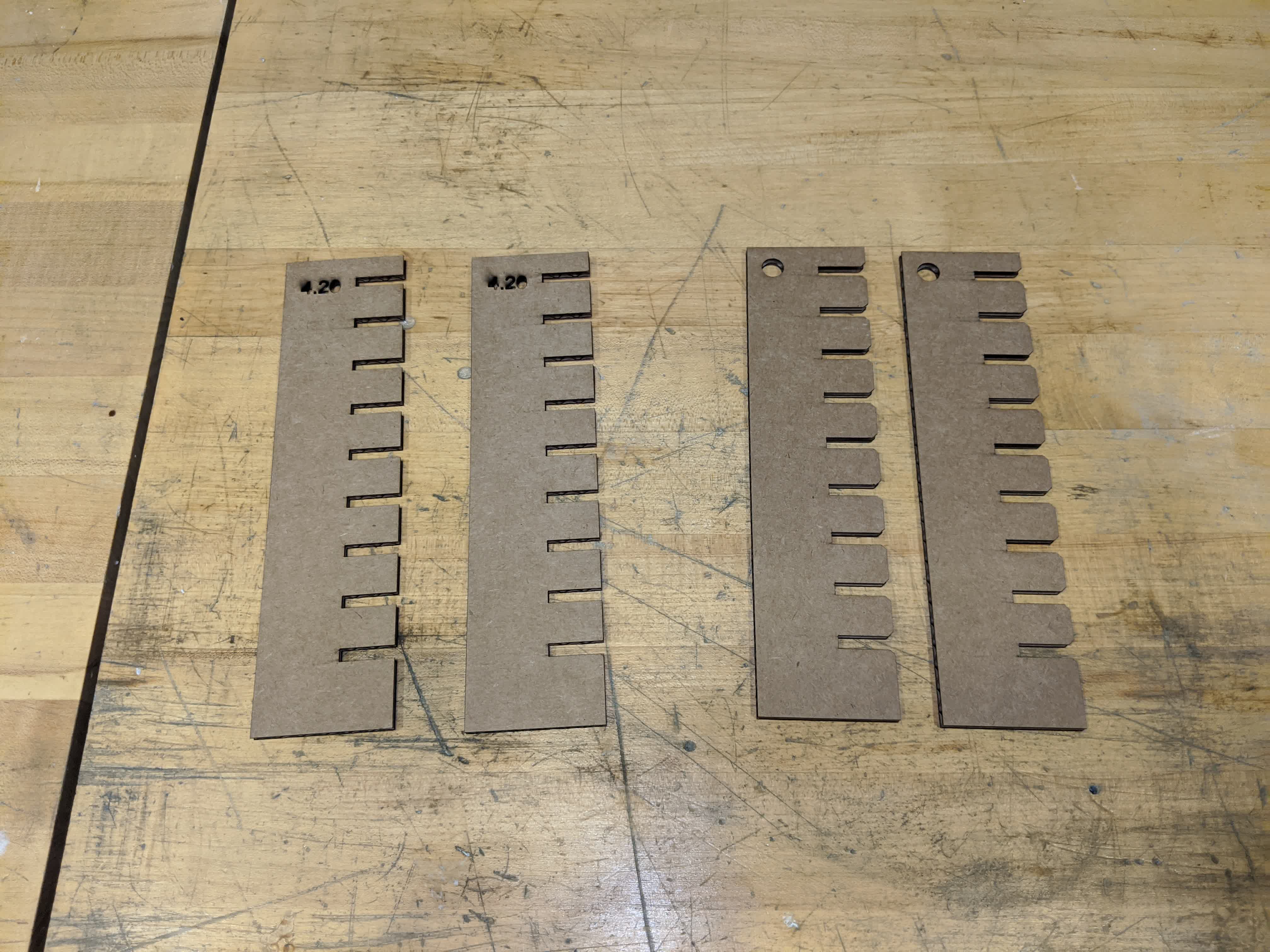
The second tests that we carried out had the goal of understanding the impact that a range of distinct tolerances can have when applied to two different
types of joints: staright joints and chamfered joints. In order to test the differences, we creted rectangles that had linearly sclaed and spaced joints.
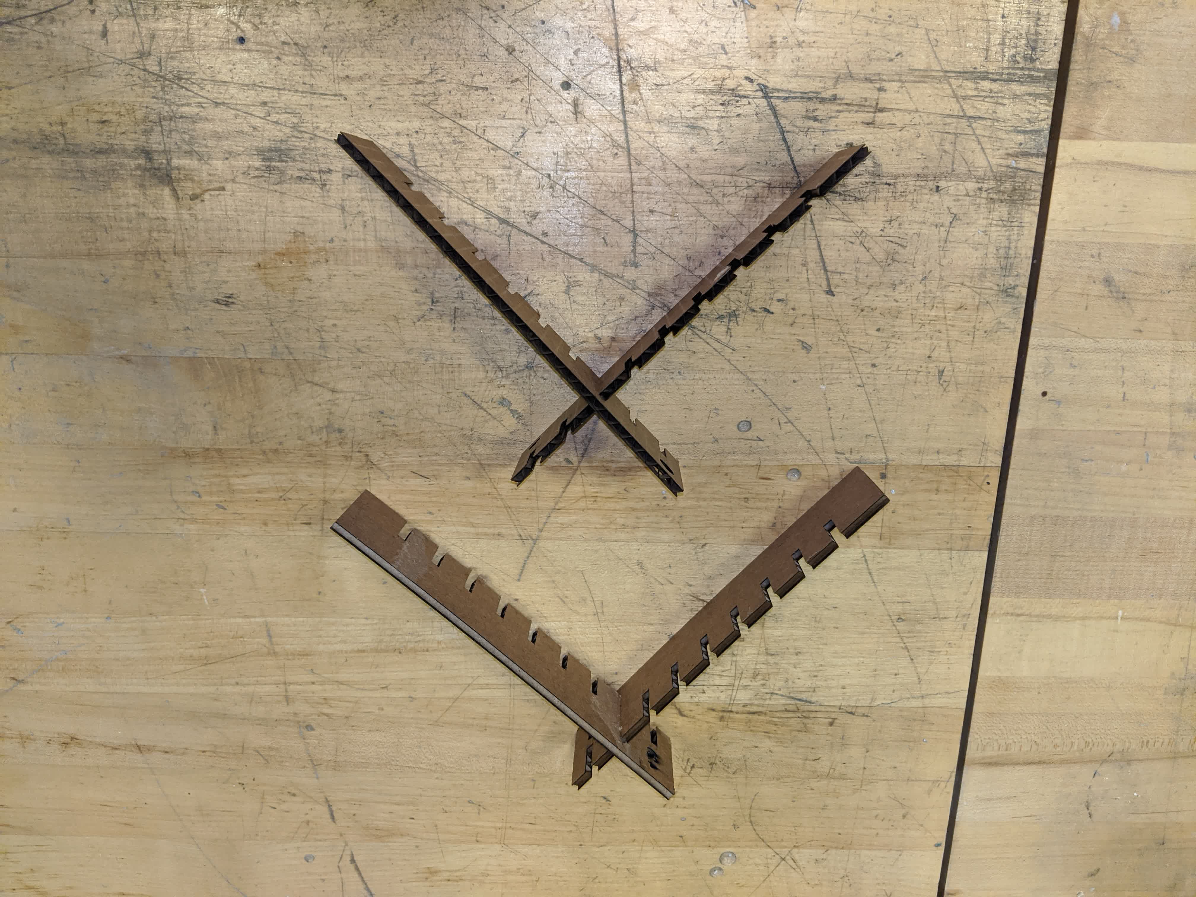
This allows for quickly testing how joints can have different characteristics. From playing around with multiple joints you get a sense of a general rule;
If you want models to be stiff and robust, joits should aim to be tighter and therefore have less tolerance. On the other hand, if the models that you are
building are complex and intended to have movement or mechanisms, it is very important to give the design more tolerances.
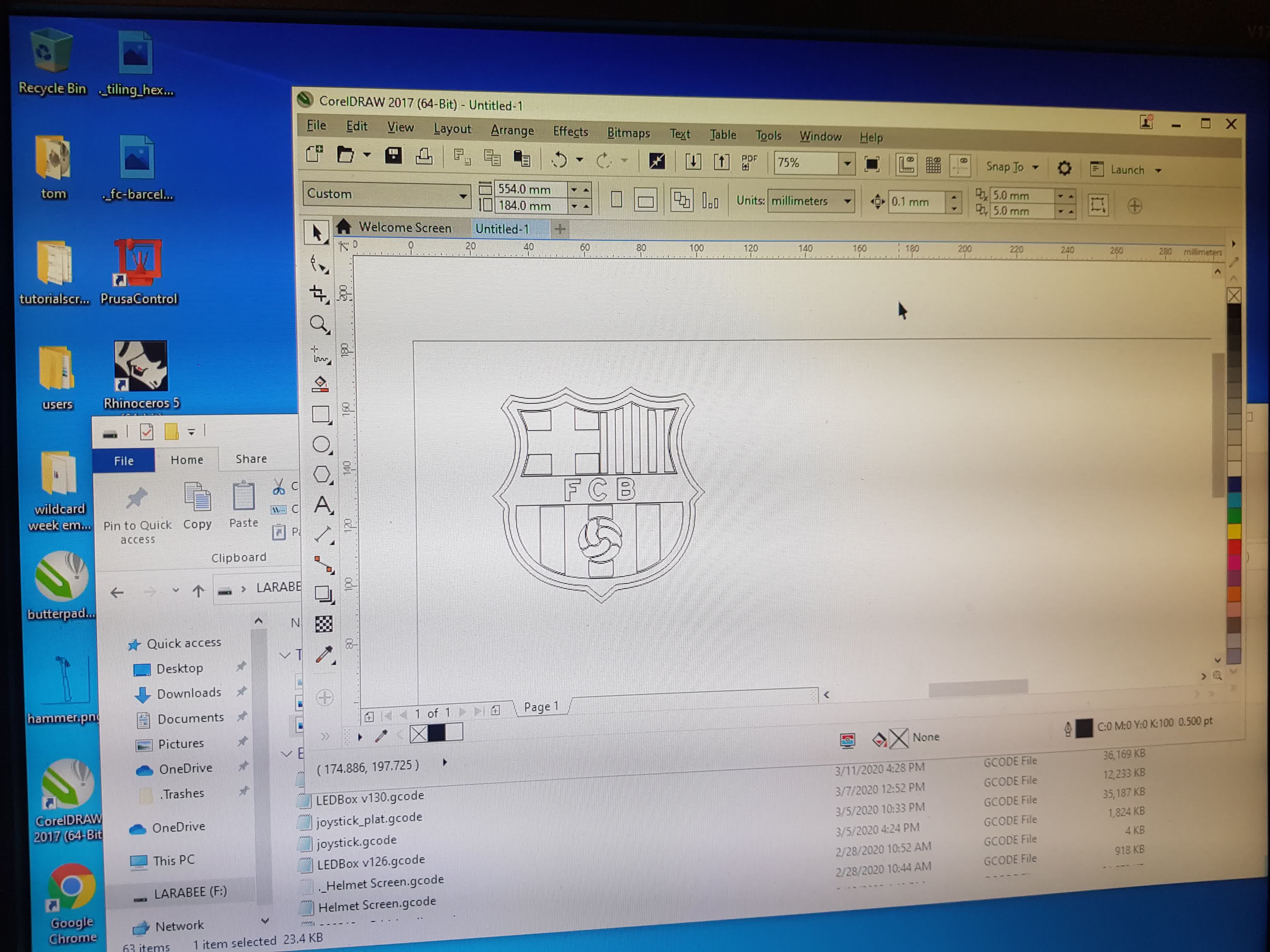
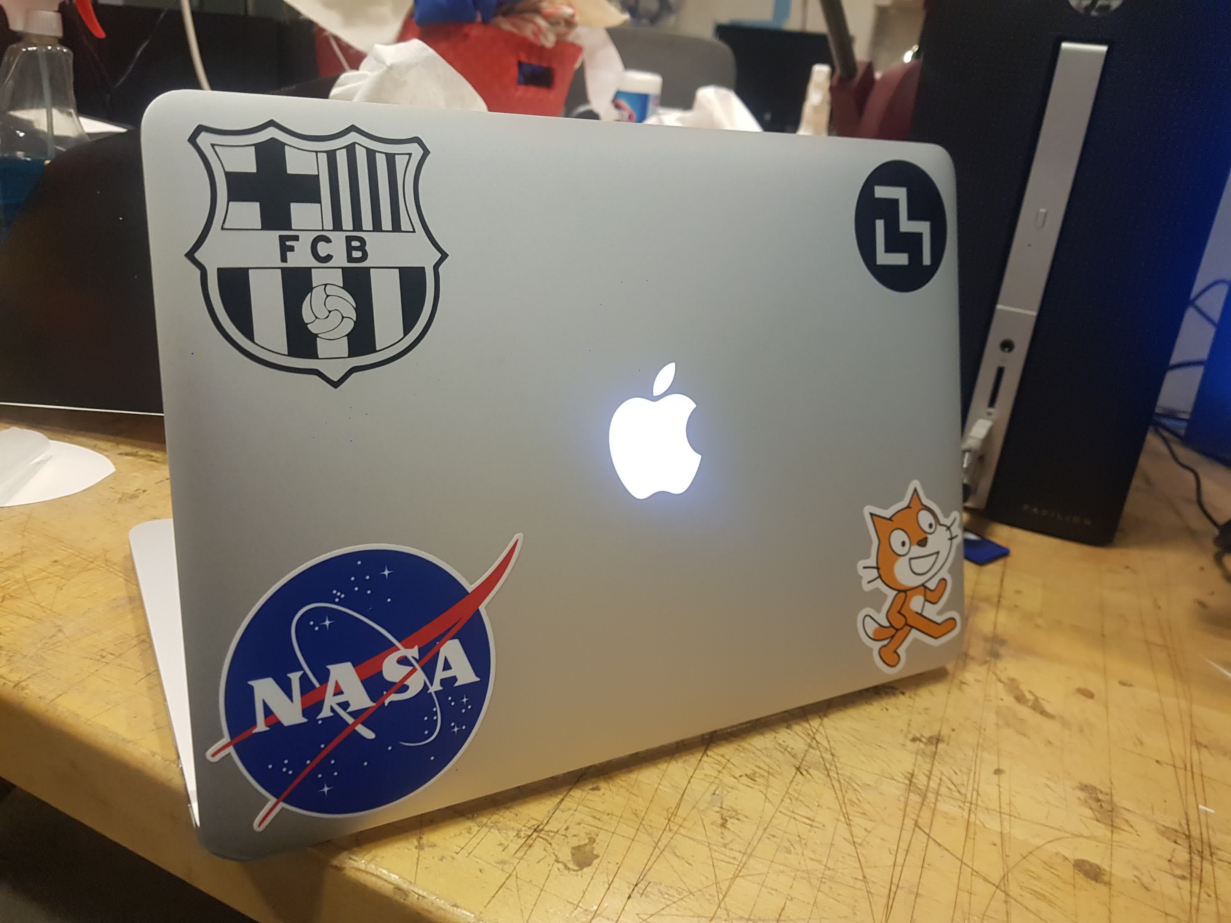
In order to get to know the vinyl cutter, I decided to cut out a stamp with my favorite soccer team's logo. I obatined a black and white png from google.
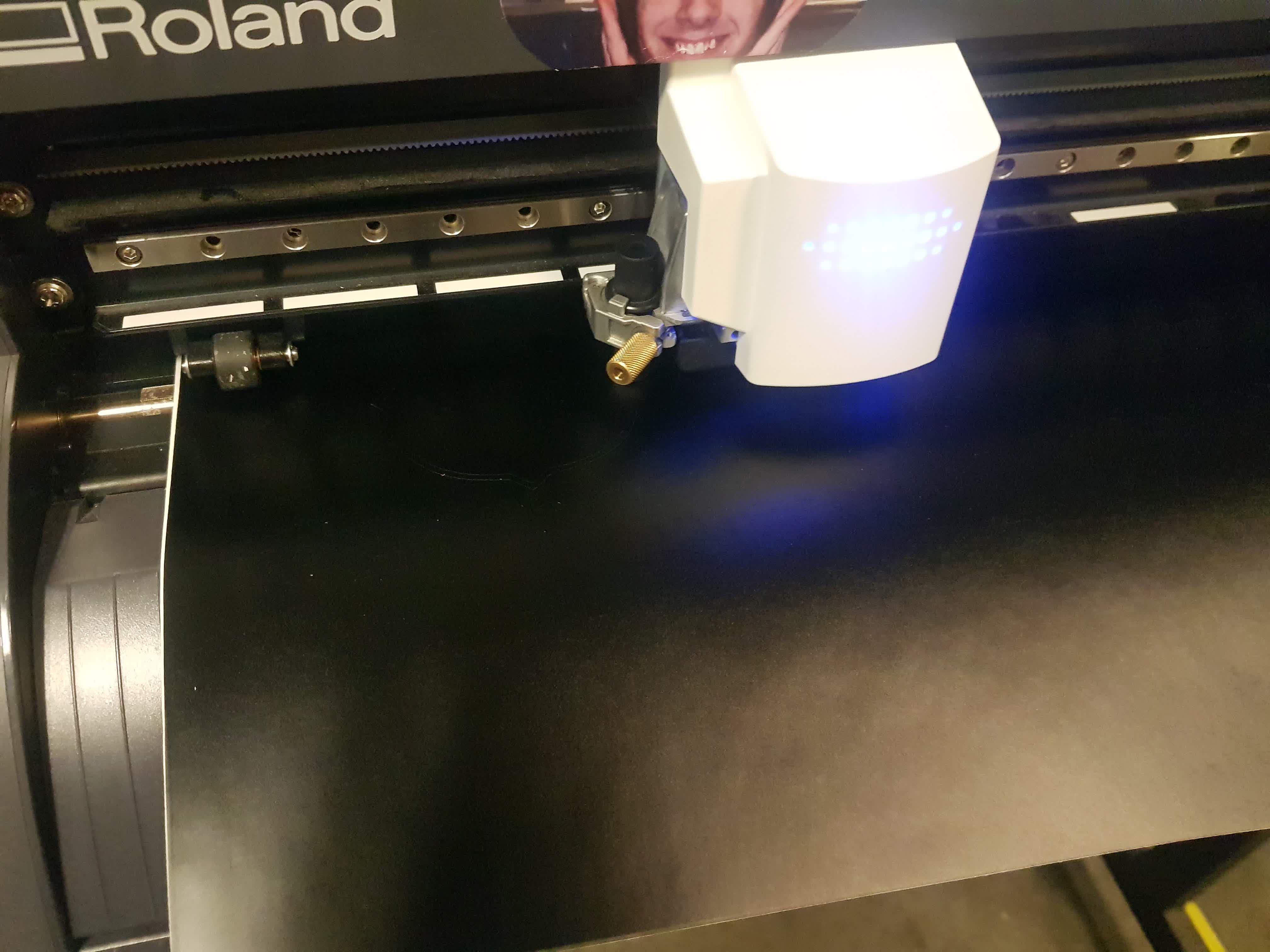
I imported the png to Corel Draw and vectorized it. Once vectorized I was able to set speed = 20 cm/s and force = 80 grams. Thos setting worked well with
the geometries of the logo. Lower speeds helped me when experiemtning with more detailed geometries.
A big lesson learned was to always verify that you do not have double lines on the DXF file. If this happens, the cutter will got over the same place and
it is highly likely that the cut won't be clean!
Cutting logo using black vinyl. Machine was manually set up.
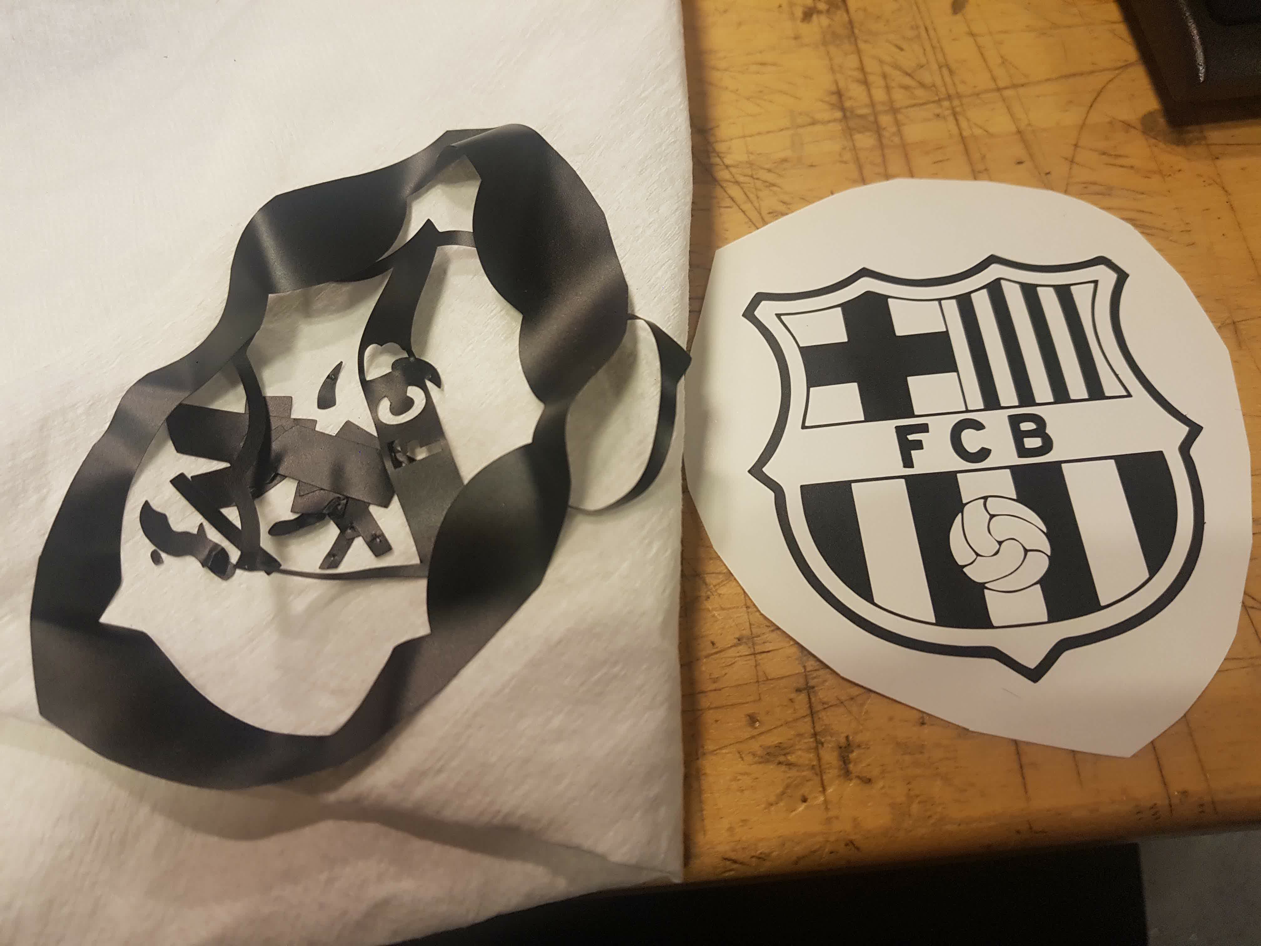
Removing scrap material to get negative mask of Logo. Pliers are very helpful!
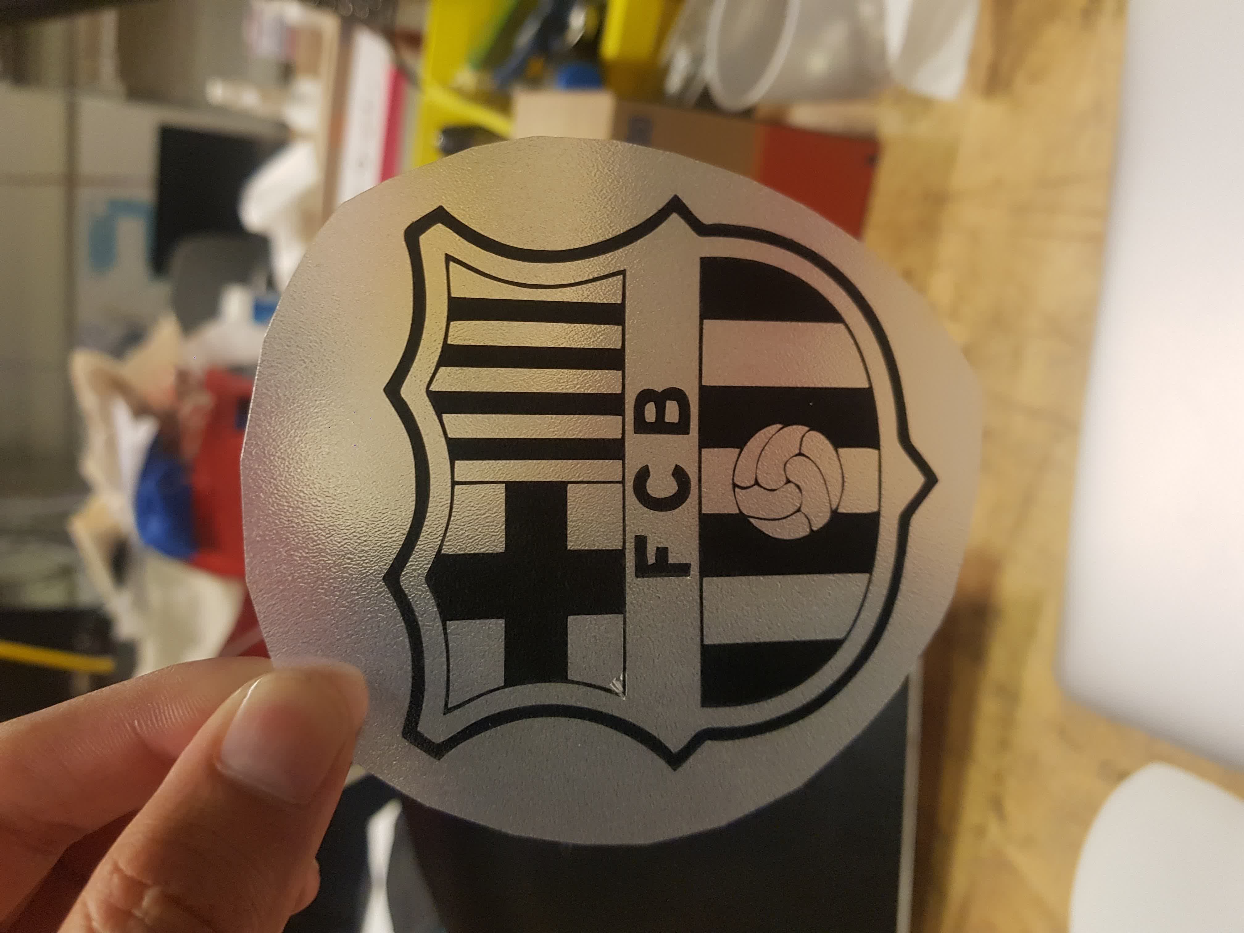
After scrap has been removed. We us transfer tape to stick the top side of the vinyl onto a rough surface that allows for laater positioning the stamp or cut
wherever we like.