W5 - Electronics Production
Assignments:
- Build Milling Machine
- Mill and solder circuit programer.
Building the clank!
This week, we got to experiment building a clank machine to set up our home labs. We received a kit containing all parts to build the machine. Setting up the machine was, for the most part, straightforward. I will give some details into the process of debugging and getting it to mill high quality PCBs. Here is a quick video of me building it!
Click To Play Video.
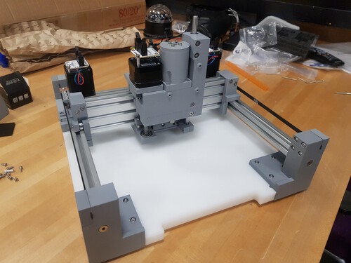
And here is the clank with the power unit installed on it. I will try 3D printing and assembling the power unit that Gil made for the class in order to keep things more safe.
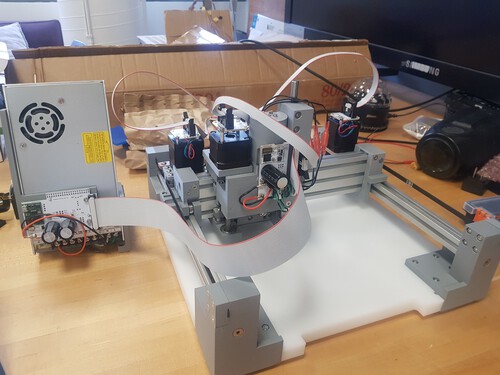
I then proceeded to install all drivers and dependencies on a local repo. Everything installed properly and I was able to get the clank powered up and moving. Here is where the problems started. My X and Z axis movements were smooth but my Y axis movement had a strange vibrations. At first I though the problemswas mechanical but after checking manual movement of belts and rollers I concluded that the problem could not be mechanical. I decided to start testing the mills without fixing the problem, thinking
Click To Play Video.
I did not find any problem that could be causing the vibrations so I thought they might not be too important for the milling process. WRONG!! I started testing the machine without fixing the vibrations and things did not go well. It was very hard for me to get a good surface finsigh on the traces and my designs seemed to always have a slight skew to them. After plenty of tests I managed to set the parameters right for tracing and miracoulosly obtained a good trace but on the moment that I tried to do the cutting paths, my 1/32 mill diead. It was clear that the mill broke because of the vibrations on the Y axis. I stopped all milling and decided to give another shot at fixing the vibration problem.
Click To Play Video.
Click To Play Video.
I then realized that the movement on Y axis was skewed to one side of the table, meaning that the problem had to be related to one of the motors. I unmounted the motors and realized that the right motor was not behaving properly. I changed the entire unit and finally got the expected smooth movement. I then began to properly make pcbs!
PCB Making
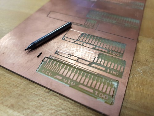
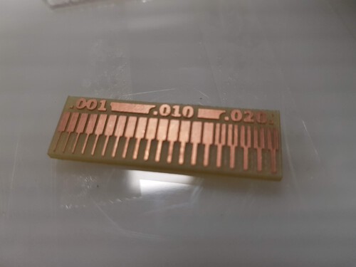
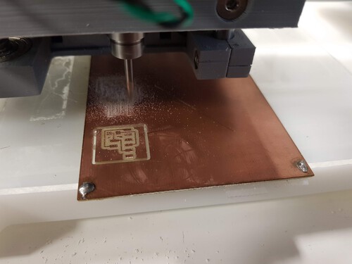
I downloaded some of the programmer boards from the HTMAA site and milled away: I found it very important to properly zero the Z axis in order to get good results with the boards. If Z axis is not well set, copper will not cut out completerly and the patterns will not come out as clear.
Click To Play Video.
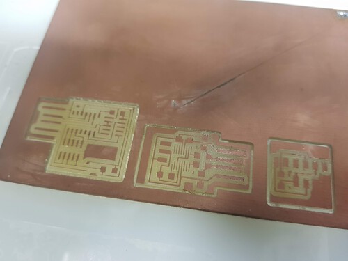
Here is a comparison of boards with varied setting for the Z axis. It is easy to see how the finish improves as I improve my zero placements. I created my Gcode using mods defaults settings.
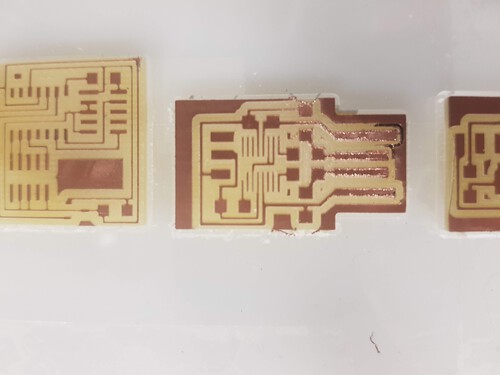
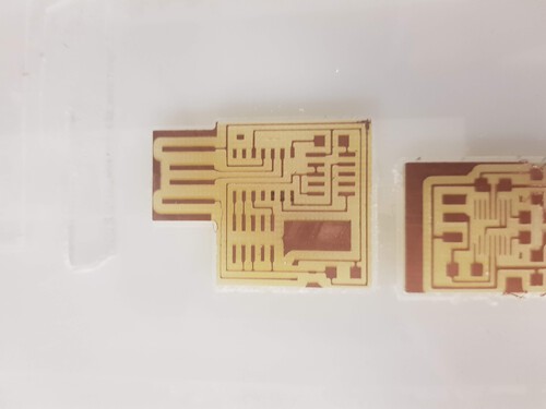
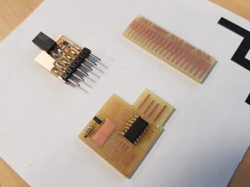
And here are the results after soldering some of the components onto the baords!