W6 - Electronics Design
Assignments:
- Design an Echo "Hello World" Chip
Designing The Chip
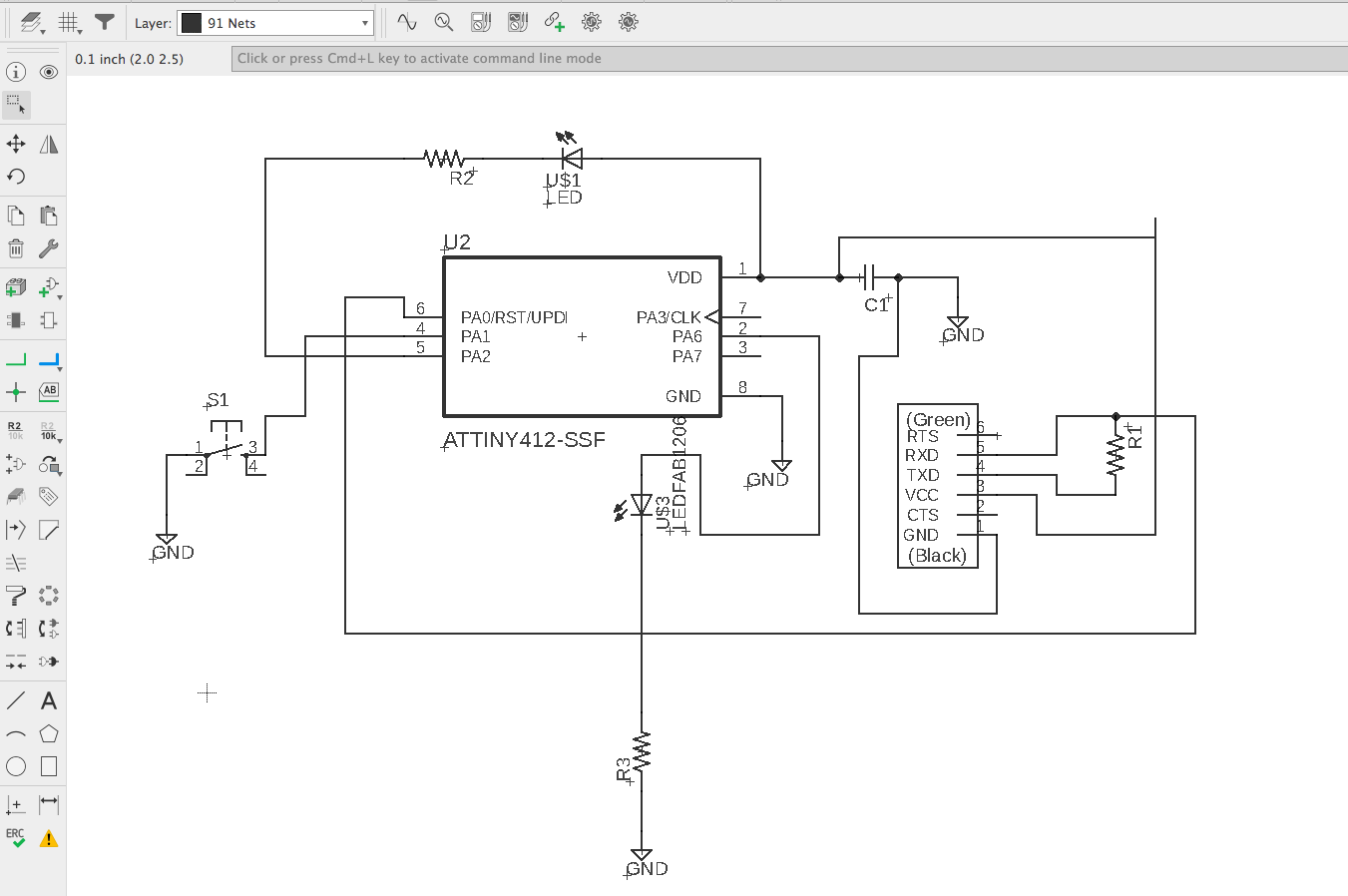
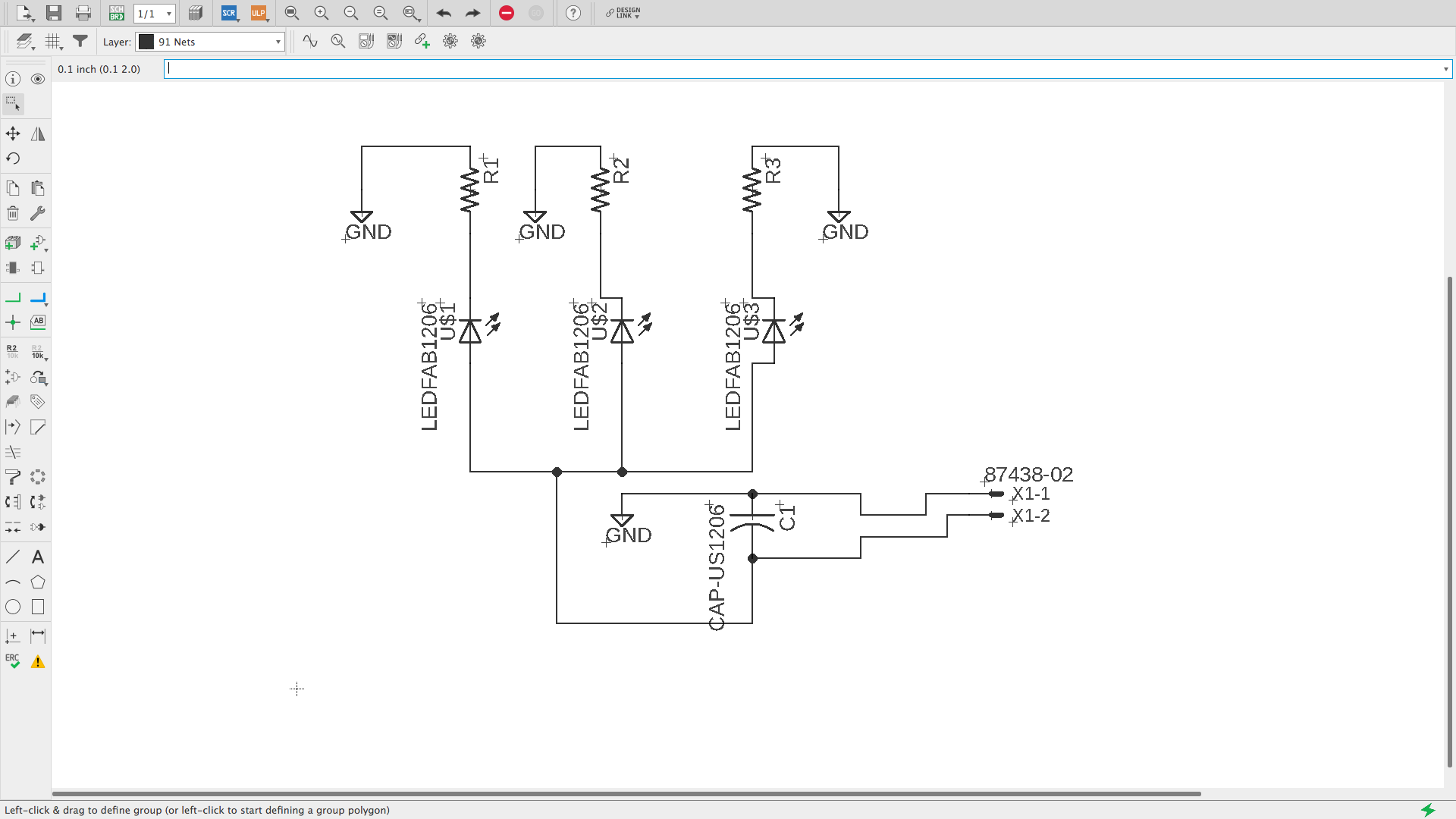
I chose to go with EAGLE as my Electronics Design Software due to the fact that almost all of my designs are done on Fusion 360. EAGLE's integration with Fusion will allow me to design my electronics alongside the mechanical parts in which they will be mounted. In past years, merging the my electronics designs with my mechanical designs has been a great bottle neck in terms of time for me so learning EAGLE will ease of this step in my usual creative process. I chose to base my design on the ATTINY412 board design that is on the class page. I understood the components of the professor's design and added two elements; push button and an extra LED. All of my past electornics work has been with of the shelf components and breadbors plates for soldering them. This production process limits my designs extensiveley. Addign EAGLE and SMD skills into my deisgn pocess will improve my prototypes in the future. EAGLE has always been a bit of a painful software for me and I have avoided getting into truly learnig it for a while but as soon as I started using it for this week's assignments I felt like a fish in water and rapidly gained good control of its basic elements and command line. I can see my workflow improving significantly in the upcoming months. I went on to draw out the design the design as seen on the pictures below. I must note that finding an ATTINY on the ATMEL library and the fab library was not possible so I created the part myself using SnapEDA. My first part had the worng footprint and I realized it when milling so I designed the circuit twice. This also helped me to better understand EAGLE's easy workflow for going from schematic to board design iterativeley. Below, you will see some images of my designs in EAGLE. I think I can improve some of the traces on the board but they will work for now.
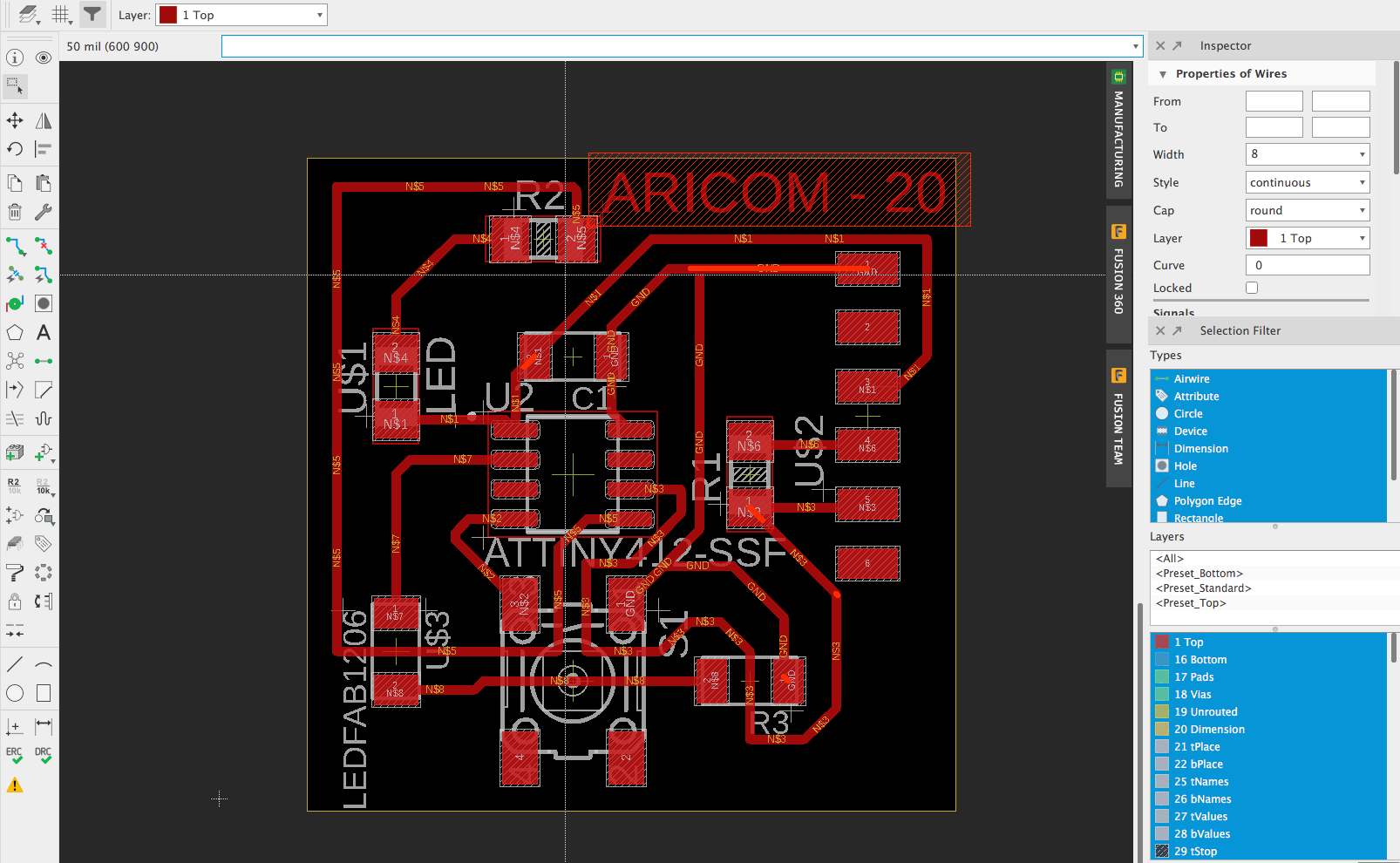
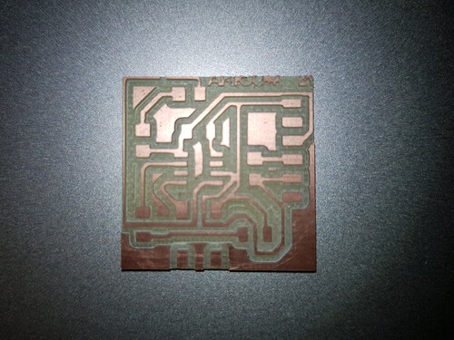
And here are my ouptput monochrome traces for inputing into mods.
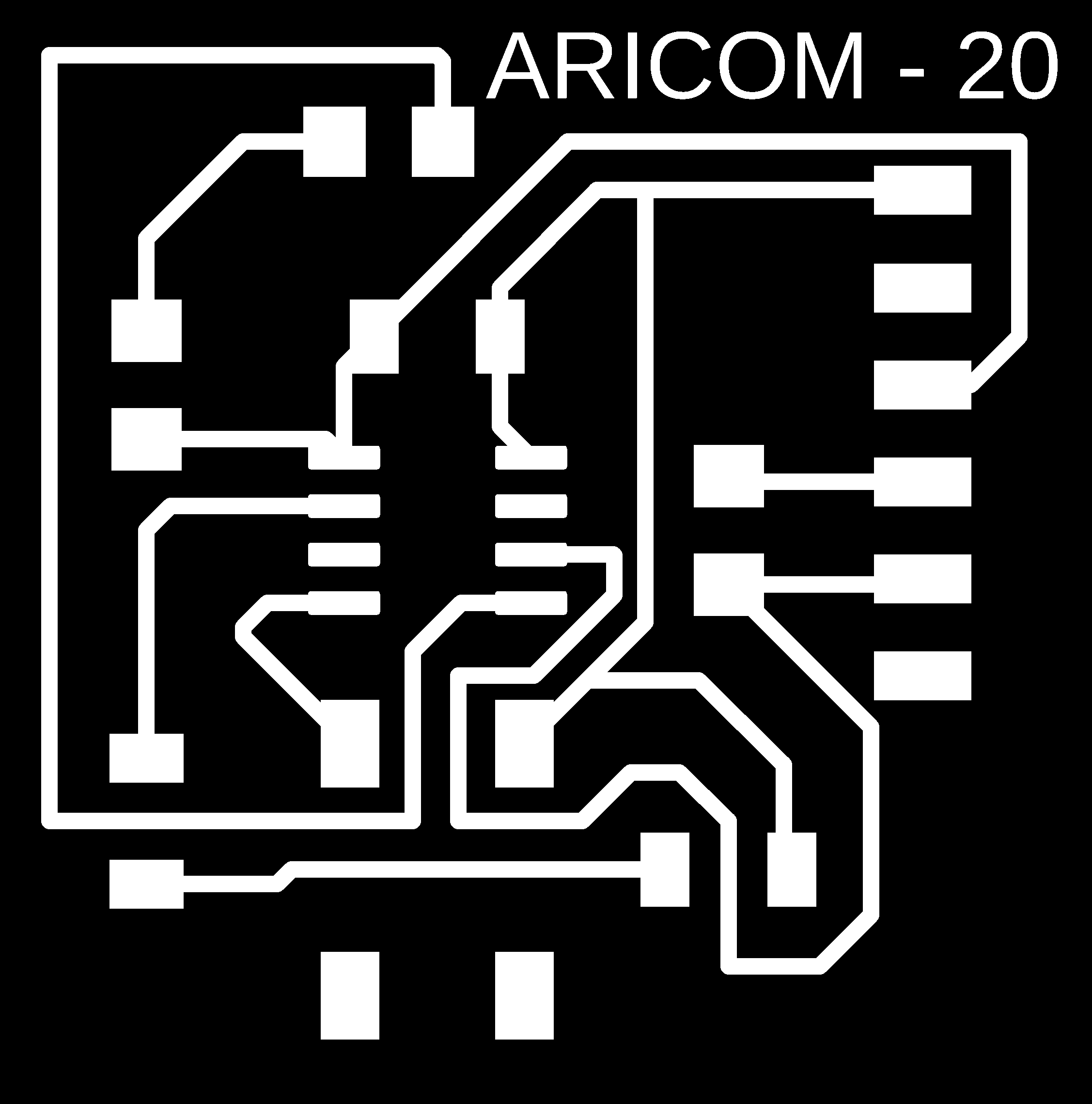
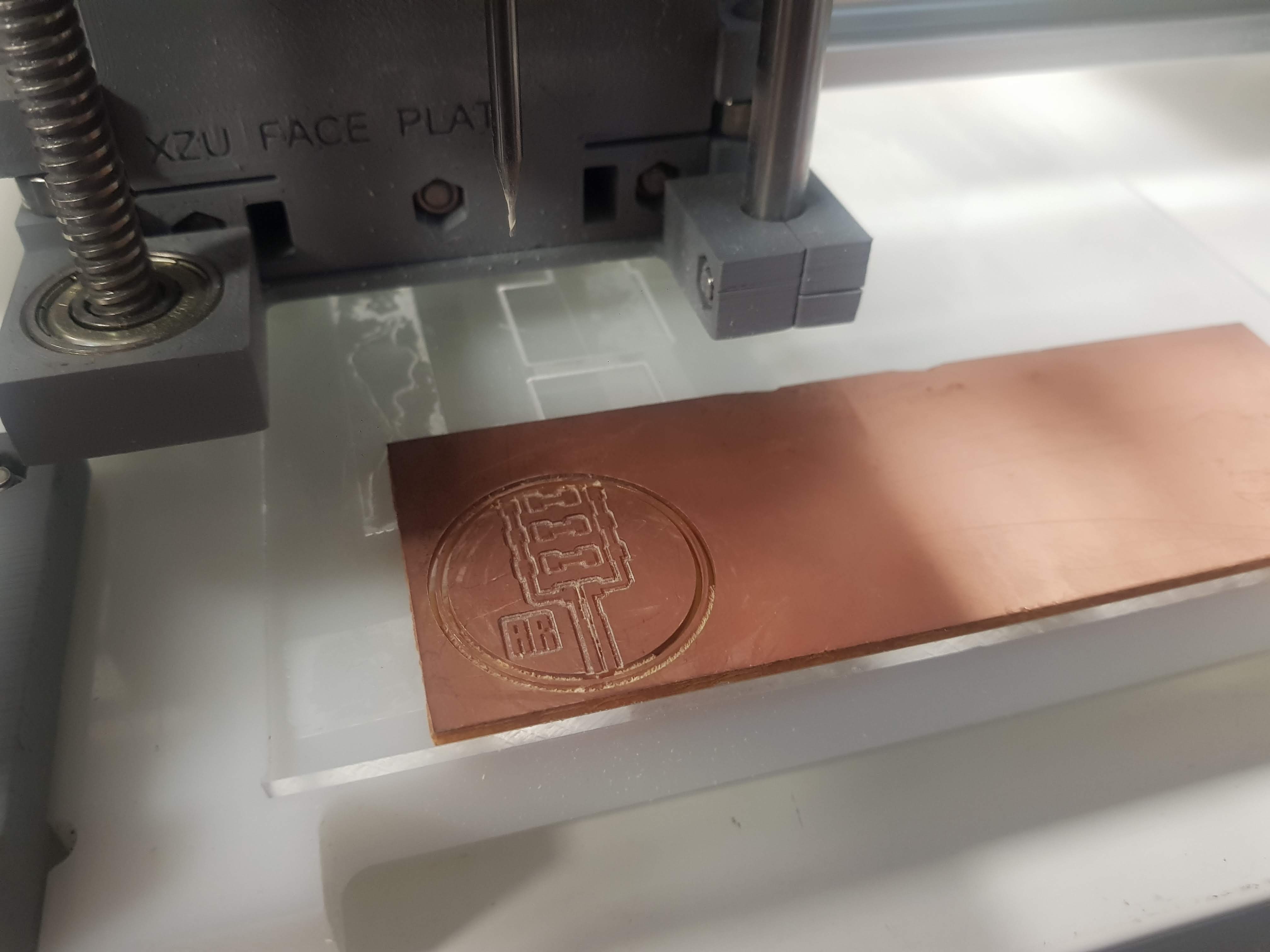
I then continued into the milling process. I used lessons and setting from last week but I still had some mistakes. The first mistake had to do with the scale of my output. It is crucially important to double the dpi number on mods for your traces png. Failing to do so will result in GCODE that mills traces that are 2x the intended size. My second mistake and third mistakes had to do with leveling my material and alligning my files properly. All the mistakes had easy fixes and no mills were damaged during the process!
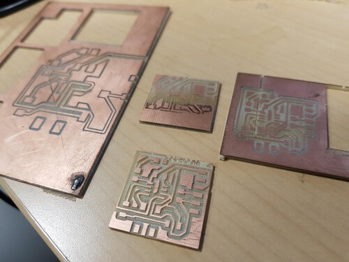
And here is the board that I chose to solder the components on!
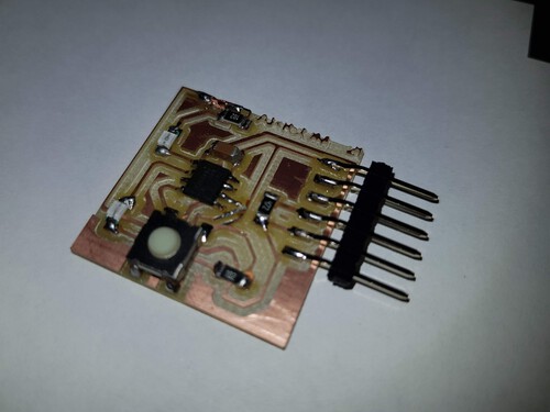
I've had plenty of experience with soldering small components so the last task was relativeley easy. We'll probably see my possible mistakes next week when I'm programming the board. But it's looking promising.
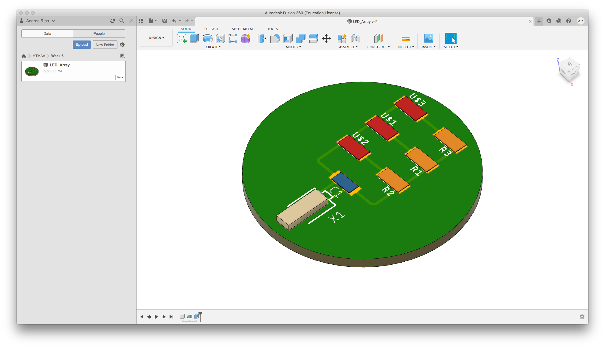
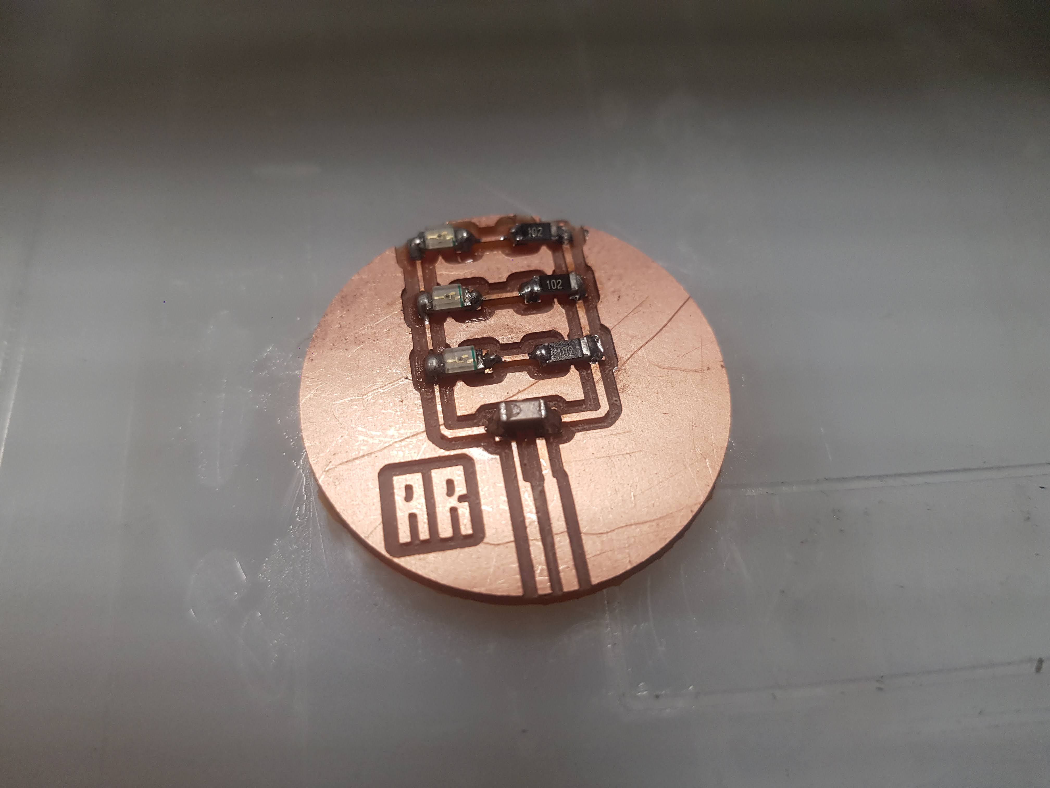
I decided to start learning some other skills within EAGLE. I wanted to know how to make different shapes on boards in order to have more experience for preparing the final project. I designed a little LED array that allowed me to test how my soldering and milling was working as well as fucntions such as adding a logo to the board. Here is the design that I made. I didn't want to add any microcontroller until after the embedded programming sessions. I learnt that for importing the logo onto EAGLE I have to pre process the image into a binary bitmap. I used GIMP for doing all the needed modifications to the image.
Milling and soldering went flawless.
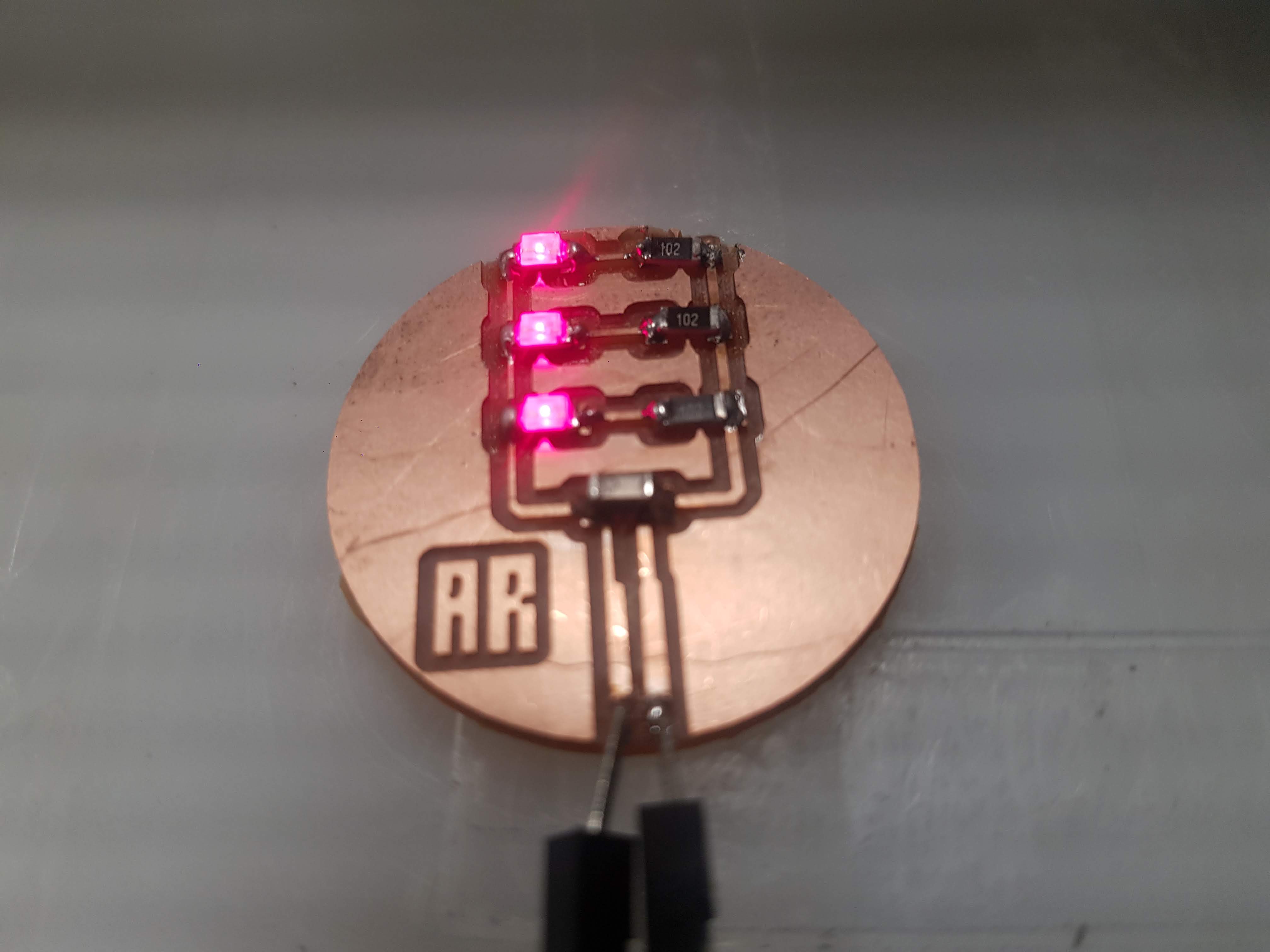
And here is the final board connected to a power source! It works great!
As an extra extra I worked on importing my design to Fusion 360. The process is very easy. i think this will allow me to create much better designs in the future.