W7 - Embedded Programming
Assignments:
- Read a Microcontroller Datasheet
- Program Board To Do Something
Reading Microcontroller Datasheet
I decided to read the ATtiny212/412 microcontroller data sheet. I've had experience reading MC datasheets before. They can be very tedious but they
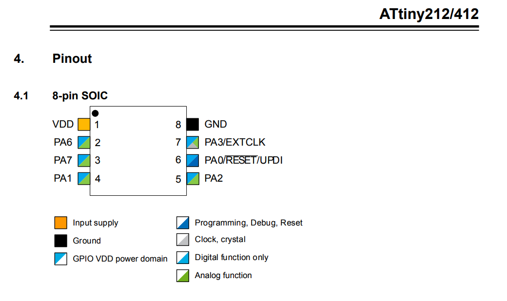
are true lifesavers when debugging and designing circuits. By far, the most useful page when it comes to a quick setup is the page that has the pinout
diagram for the MC. This pages allows you to see, at a high level, what each pin is for. When looking to set up a board with simple functionalities this is
page to visit!
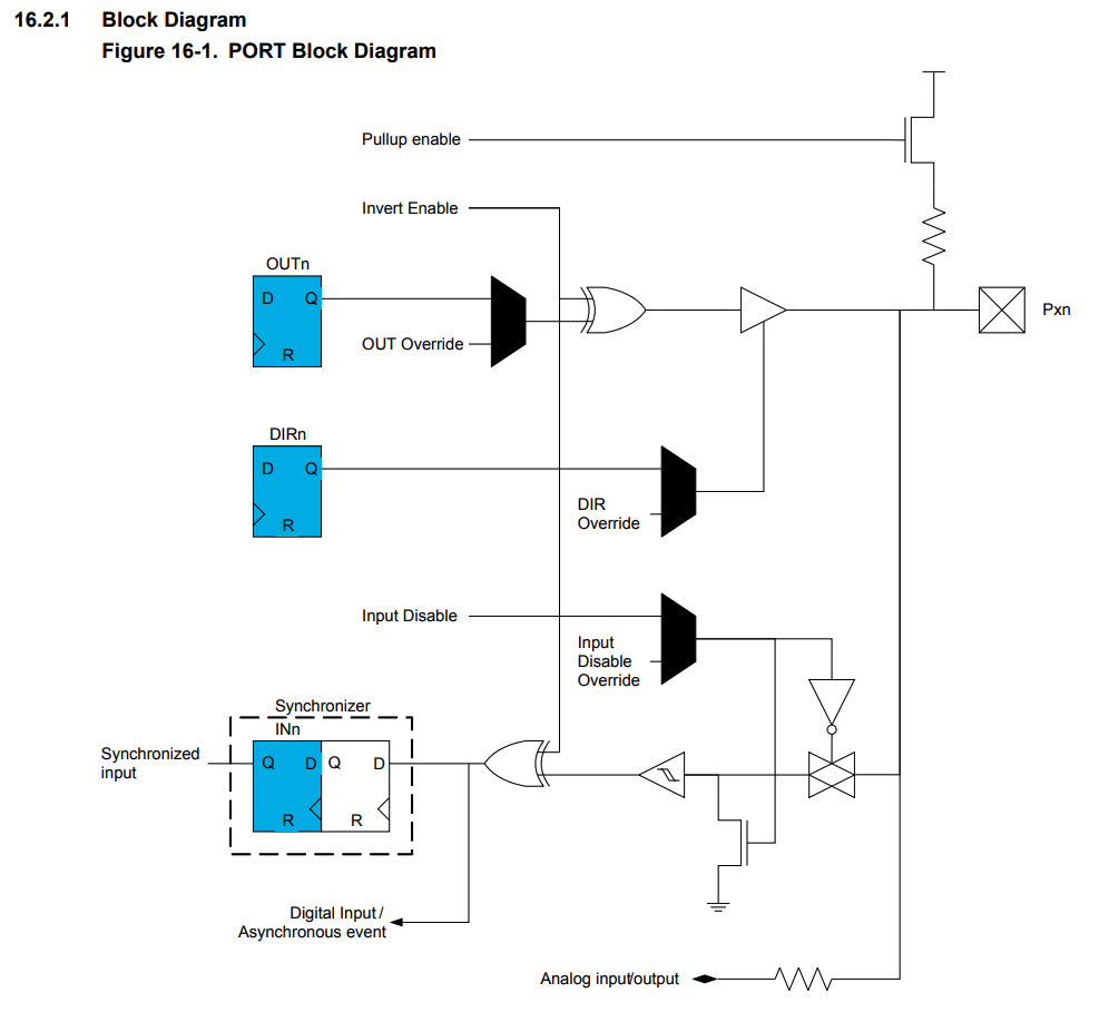
My board design makes use of the internal pullup resistor that the MC's pins have. You can find diagrams of for each port's internal connection on the data sheet as well.
This knowledge can help you simplify your external designs component wise.
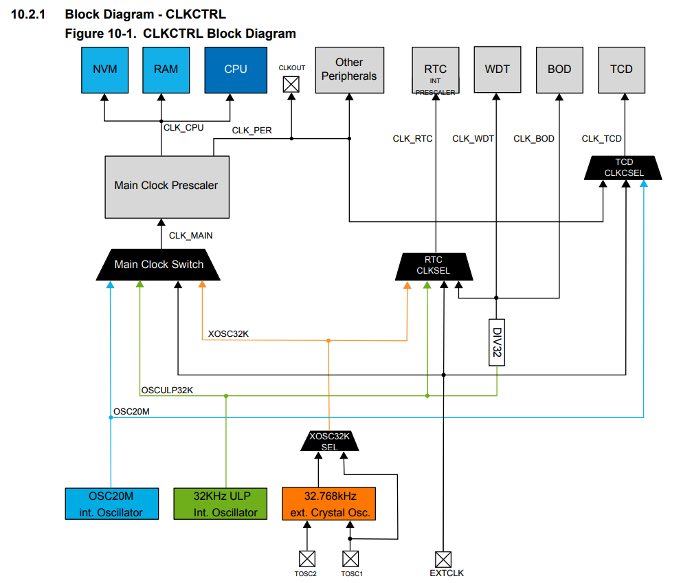
A neat function of this MC is that you can use external clock to run it. This allows for flexibility when designing more complex systems. Thankully, we can find
information about connecting external clocks to the MC.
Sleep Mode! Sleep mode is a function that allows for great saves in energy. Many of the applications that I'm thinking to give my circuits could benefit greatly
from this fucntion. I'll try to enable it for my final project! We'll see how it goes. The date sheet is a bit hard to understand but it gives good pointers towards what one
should be thinking about for being able to enable sleep mode on the tiny!
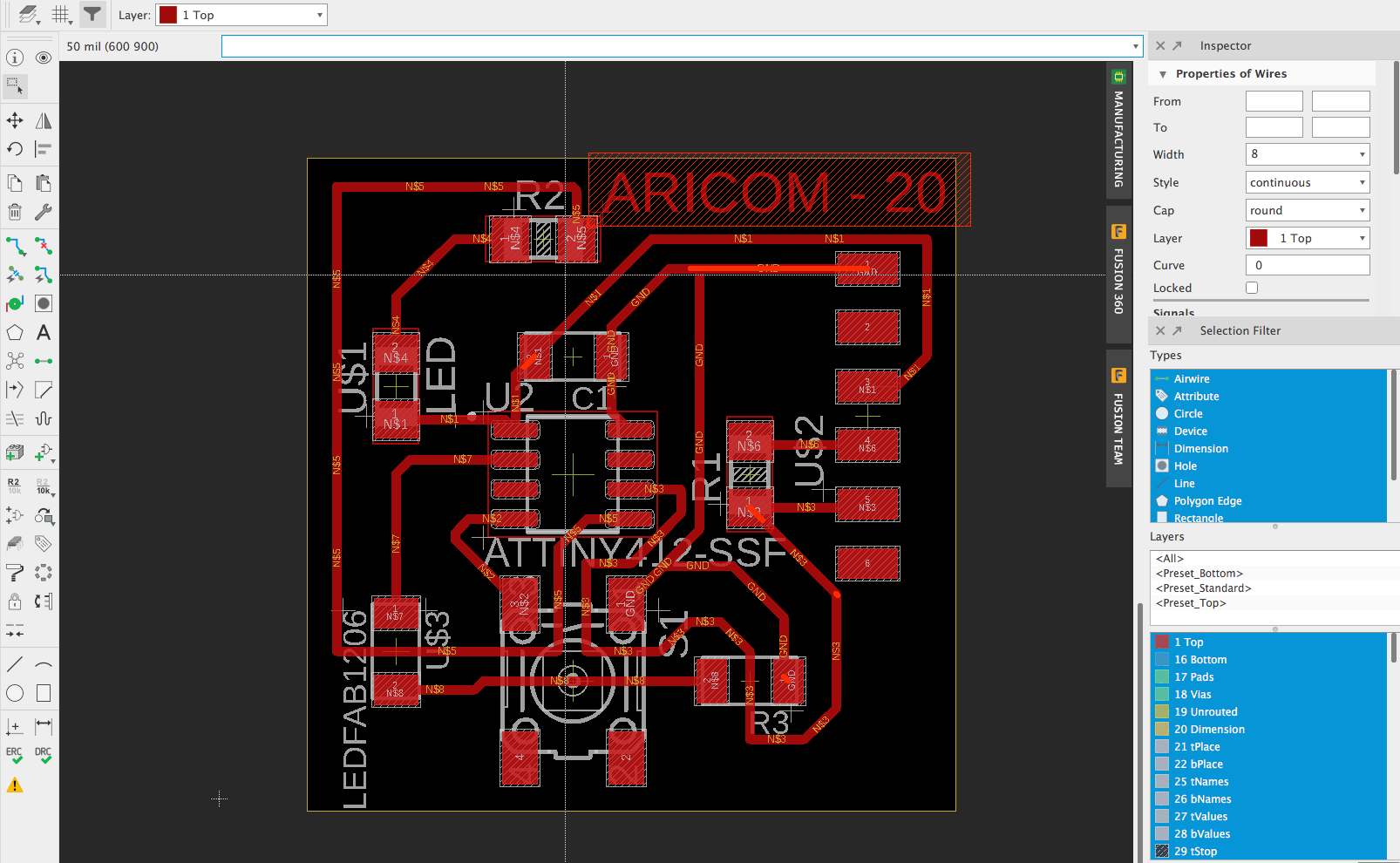
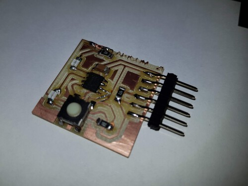
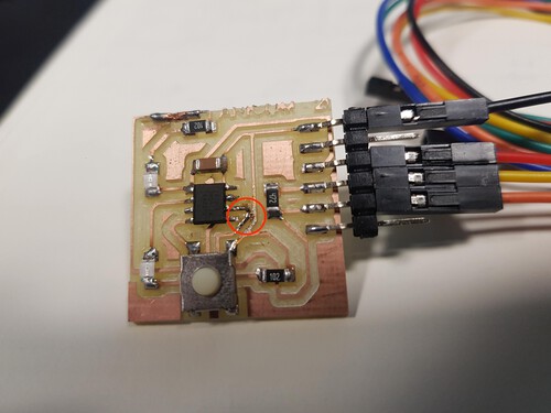
On week, I designed a board that was based on the ATtiny 412 MC. This board has very simple functionalities but it will allow me to test out my embedded programming skils and
to debug any problems that might arise for when I'm designing my final project's boards. My board contains a updi connection for programming the MC, two LEDs and a push button.
One of the LEDs is connected from the main voltage source to one of the pins so it makes use of the internal pull up resitor to switch it on and off. The second LED is connected from the
MC's pin to ground. This switches the logic of activation for the second LED. Below is my schematic and circuit.
I decided to use the Arduino IDA editor to create my program. At first I used the classes blynk example in order to test the uploading sequence before
testing my programs. I've used multiple cores and boards but had never programmed the ATtinys directly so I had to installl the library from the boards
manager.
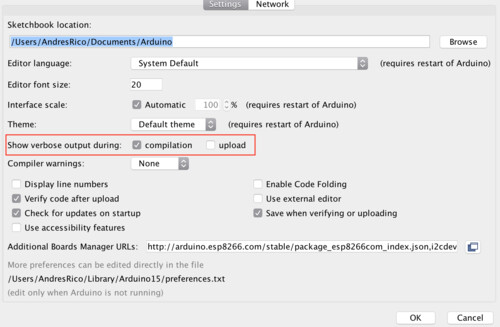
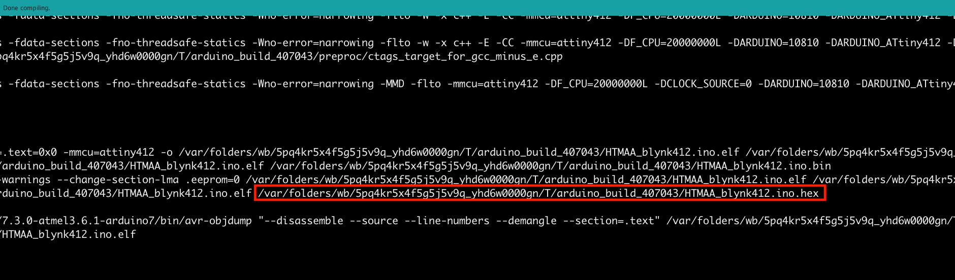
Once that was done, I made sure to have the compilation box checked on the "Show verbose output:"" settings. This setting allows you to see all the compilation output on your console.
You need to see the ouptut in order to find the location for the .hex file made by the IDE when you verify a program.
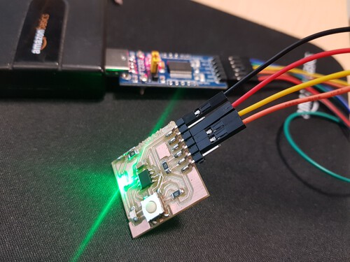
With all those settings checked I went ahead and connected my board with the FT232 kit board as follows:
| VCC - VCC | | GND - GND | | TX -vRX | | RX - TX |
I then went on to connect the board to power. I immedeately saw the LED that was connected from VCC to a MC pin light up. I was not expecting this,
but thought that maybe the default pin setting was making it light up. I then realized that I had a mistake on my board. The pins trace was connected to GND!!
I made use of the handy cutter tool to assure the traces were correct. Thats a late lesson from two weeks ago.
After fixing my board I verified my program on the Arduino editor by clicking the circle with a check. As expected, my program compiled correctly and a
.hex file was saved.
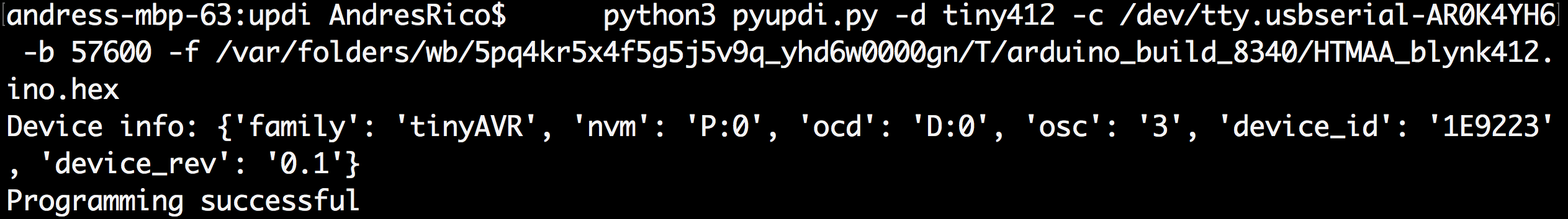
I then installed the great pypudi repo. This repo has a python script that allows you to flash the .hex file into the microcontroller. A couple of notes on this
would be to make sure to use sudo pip install (repo link). This will make sure that all fucntions have the appropiate permissions. After installing, I navigated
to /pypudi/updi/ and ran the pyupdi.py script with the following command:
python3 pyupdi.py -d tiny412 -c /dev/tty.usbserial-AR0K4YH6 -b 57600 -f /var/folders/wb/5pq4kr5x4f5g5j5v9q_yhd6w0000gn/T/arduino_build_8340/HTMAA_blynk412.ino.hex
The script ran succesfully. I saw the TX and RX LEDs light up and my board started working as expected.
I made a very simple program that lights on one of the LEDs on setup and then uses the button to controll the second LED. The button acts as a
virtual switch. When pressed it turns on the LED, if you press again, it will turn it off. If you press and hold, the LED blynks. Here is the code:
And here is my Demo! Click to start video.
Programming my board...

#include