W8 - Input Devices
Assignments:
- Measure Something
Designing the board
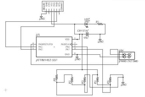
This week I will be testing board designs that will be implemented on my final project's sensor spheres. To start me off with input devices I desided to build a temperature sensor board. The board will be based on an ATTiny 412 MC. I used the same process as the one I have used for past electronics weeks. I made my design with EAGLE. Here is my schematic.
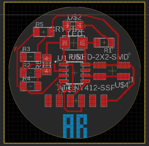
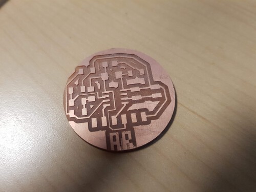
I experimented with making custom shapes and dimensions within EGALE. The board has a 30mm diameter and is centered at EAGLE's origin. This adds flexibility to when I modify traces and outlines further down the process. I'm also practicing adding external bitmaps to have my initials on the boards. This is how my final board design looked like. The external dimension square is only used to offset the exportation of my png so that my outlines have enough room on the edges. This helps mods create gcodes succesfully.
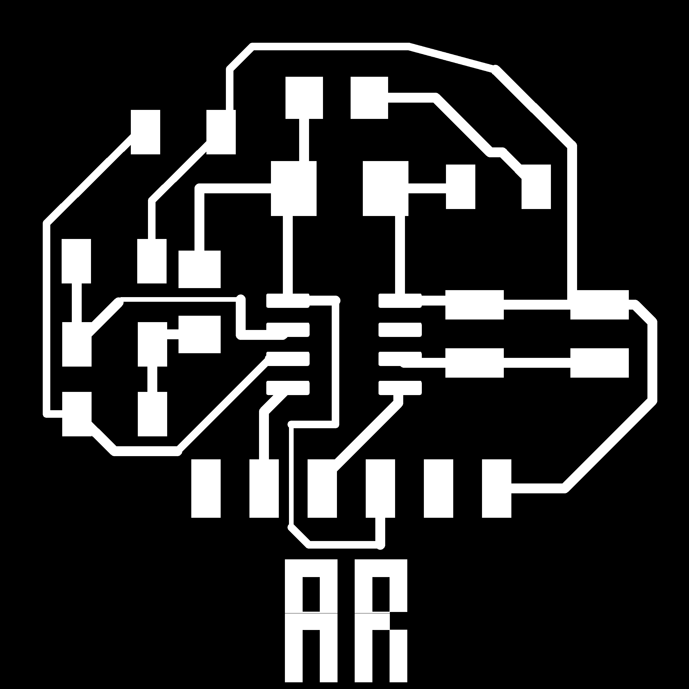
This is how my final png traces looked. I have no idea of where the line across my initials is coming from but it didn't matter when creating my GCode. An important lesson from this week was that I used different trace widths in order to get all of my traces properly calculated. Using the same trace width did'nt allow me to create proper trajectories for all of my components.
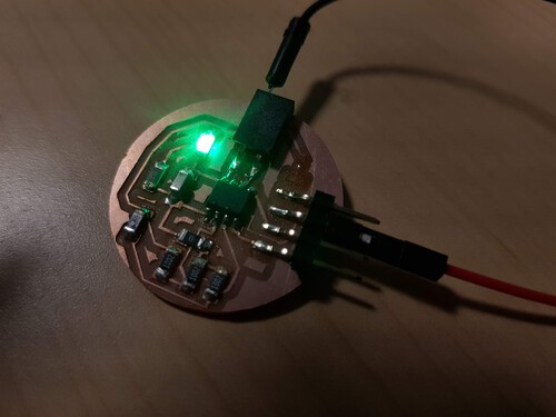
Milling and soldering went well. It was great to see that all of my components were working as expected and that I did'nt have to go back to EAGLE to fix mistakes.
And here it is powered up and ready to sense!
Programming my board...
Programming the board went well. This time, I built in the UPDI adapter to the board so that I could manage to have communication fro programming it as well as serial output for viewing my sensor's outputs. I used the simple program below to convert from my analog voltages into temperature value in Celcius. The program works well but I've been struggling with the last print statement. I cannot seem to print my final Tc float.
      #include
      #include

      int refPin = 0;
      int ntcPin = 1;

      void setup() {
        // put your setup code here, to run once:
        Serial.swap(1);
        Serial.begin(115200);
        pinMode(refPin, INPUT);
        pinMode(ntcPin, INPUT);
      }

      void loop() {
        // put your main code here, to run repeatedly:

        int Vref = analogRead(refPin);  //Reference Voltage.
        int Vntc = analogRead(ntcPin);  //Tension on NTC.

        Serial.print("Reference: ");
        Serial.println(Vref);
        Serial.print("NTC: ");
        Serial.println(Vntc);

        float Intc = (2*Vref - Vntc) / 10000;

        float Rntc = abs(Vntc / Intc);  //NTC Resistance Calculation.

        float Tk = 1 / ((log(Rntc / 10000) / 3750) + (1 / 298.15)); //Scale resistance to temperature in kelvin.
        float Tc = Tk - 273.15;  //Convert from Celsius to Kelvin.

        //Serial.println(Tc, 4);
        delay(250);

      }
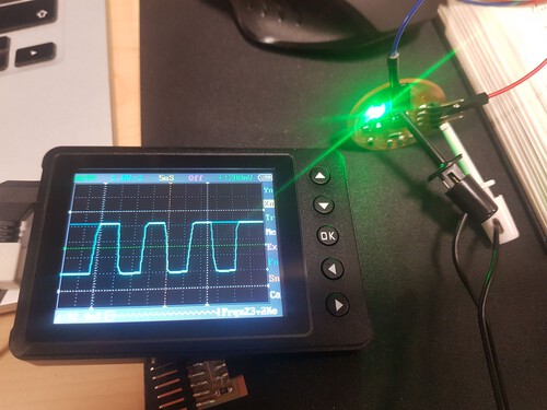
Using our awesome portable scope...
Finally, I got to using my handy portable scope. I probed my data lines. As expected I could see the square waves appearing from mi MC sending data over its serial lines. The data is being sent at a baud rate of 115200. This little guy will be extremely handy in the upcoming weeks!