W9 - Output Devices
Assignments:
- Connect a Board to an Output Device
- Measure Power Consumption of Output Device
Designing the board
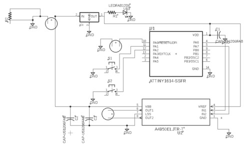
This week, I moved on to programming the ATTINY 1614 MC. This is a more capable MC than the 412, which I used for my past assignments. The reason for migrating MC is to start experimenting with a MC that will be able to give me all the nessesary pins for my final project. I will be using RF to communicate my devices so having enough pins for communication will be necessary. This week I decided to do a simple motor driver. The driver has two built in push buttons which will allow me to control the motors spin direction. Many of the projects that I'm working on at my lab require controlled motor actuation so I will be using this design for many of my projects in the future.
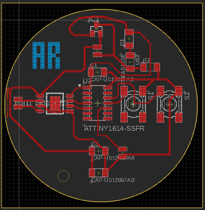
I created my design using EAGLE, as usual. I had to look for more pieces than usual this week. Some of the components are not on the latest version of the fab academy library but I managed to find somw properly designed devices online. My schematic and board looked something like this.
As a side note, I decided to begin experimenting with making holes on the middle of my board so that I can mount the with screws onto cases in the future. Tolerances for the screw holes are a bit tricky because they get scaled when exporting from EAGLE and importing into mods.
Some of the traces that I designed were a bit too thin for my milling machine and did not come out well traced but I used copper tape to fix them so that I would'nt waste my board. Soldering and fixing the damaged traces went well. Once everyhting was in place, I powered my board and everything seemed to be working as expected. I measured voltage across different pints and was able to see that I had 12 V and 3.3 in the places were I wanted.
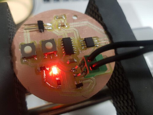
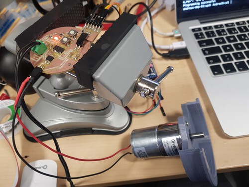
I then connected a 12V geared DC motor to the output terminals of my board. Now all I had to do was program the board.
Programming my board...
I decided to use the simple Arduino IDE and fucntions. I just wanted to quickly test if my hardware was working properly. I created the following code and uploaded it without any hassles.
      int motor_1 = 2;
      int motor_2 = 3;
      int left_button = 8;
      int right_button = 9;


      void setup() {
        // put your setup code here, to run once:
        Serial.begin(115200);
        pinMode(left_button, INPUT_PULLUP);
        pinMode(right_button, INPUT_PULLUP);
        pinMode(motor_1, OUTPUT);
        pinMode(motor_2, OUTPUT);
      }

      void loop() {

        digitalWrite(motor_1, LOW);
        digitalWrite(motor_2, LOW);

        while (!digitalRead(left_button)) {
          digitalWrite(motor_1, HIGH);
          digitalRead(left_button);
        }

        while (!digitalRead(right_button)) {
          digitalWrite(motor_2, HIGH);
          digitalRead(right_button);
        }

      }
And here is my Demo! Click to start video.
Calculating motor power consumption...
I then got my multimeter out to measure the volts across my motor leads and currrent flowing through my wires.

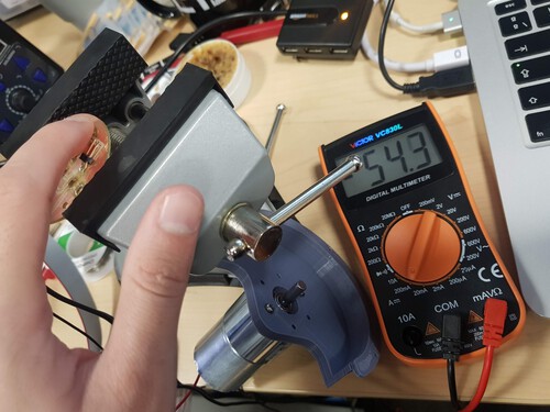
I measured 12.24 V and 54.3 mA so that would mean that my motor is consuming .664 Watts. Not bad!