Electronics Production
This week, we started moving away from the bigger machines we were using in the lab to some skills and fabrication processes that we could do at home (you know, because of the global pandemic...) So, we learned how to make our own circuit boards by milling and soldering components onto those custom PCBs. While we're not designing the PCBs ourselves this week, we do need to learn how to make them and solder them. So, let's talk about making the circuit boards first.
In a typical year for this class, we would probably just use a PCB milling machine in the lab, such as the Roland SRM-20. However, in attempting to move as much fabrication into our own homes as possible, this year we were provided with home lab kits. This is in line with the ideas of personal fabrication becoming more and more accessible to more and more people, and has been a good test to see how well such an idea works in practice. I mean, 3D printing has become accessible enough for people to bring them into their homes, why not PCB milling?
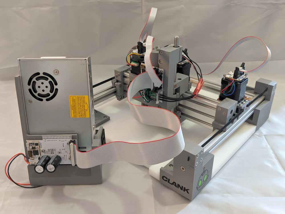
Jake Read, one of the PhD students at CBA, worked all summer to design such a milling machine, which he named Clank (from the Ratchet & Clank games). He also worked with Zach Fredin, a Masters student at CBA, to source all of the components and parts each student in the class would need to build and run Clank, as well as solder the boards we make with Clank, and a bunch of other various things like document our work. They did an absolutely phenomenal job with this, and I'm so grateful to them for what they did to make this class go well and provide an awesome learning experience for us. For more info on the home lab kits, click here.
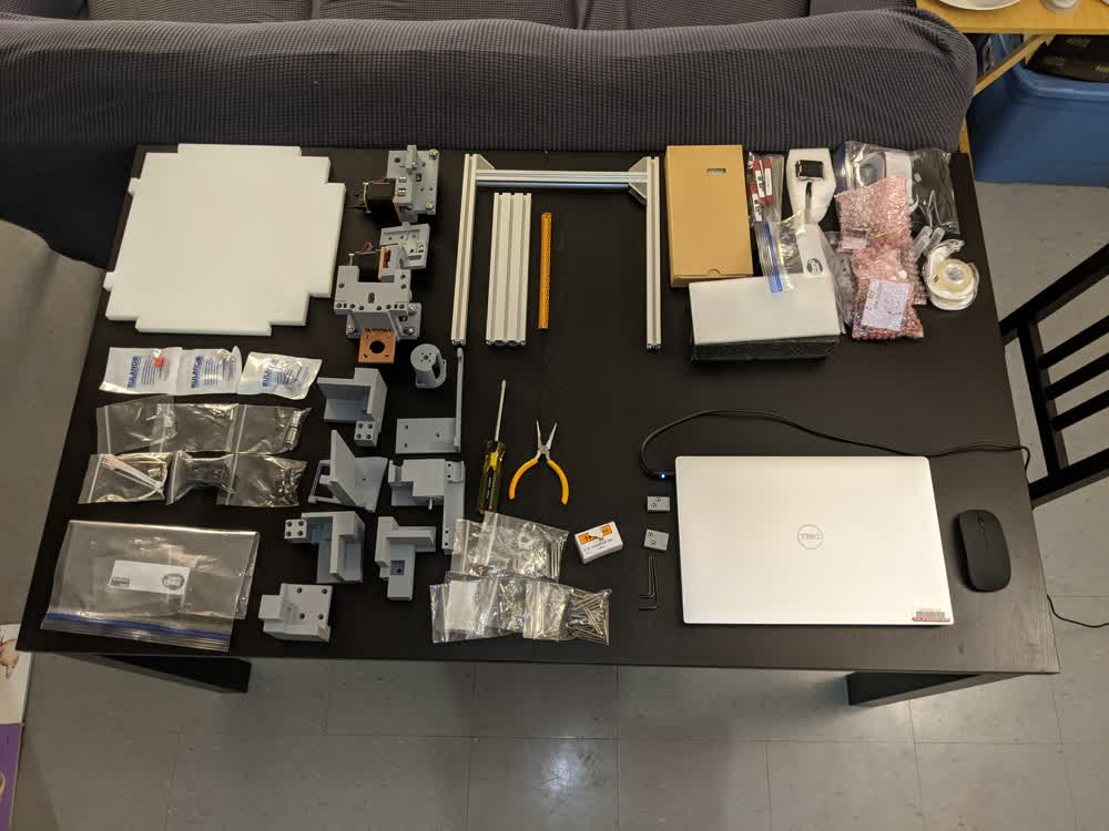
Jake made some wonderful videos to follow along to go through the build process of Clank. It took me a couple of sessions to get everything put together (I had some delays because I overlooked some parts and couldn't find them in the beginning), but it was quite the fun process. I was incredibly bummed to realize at the end that we had been given a ball-end hex key, and I had been using a flat-end hex key the whole time... The ball-end would have made things a lot easier... Also, I had put one of the motors on incorrectly, so it took me a while to get it off and rotated.
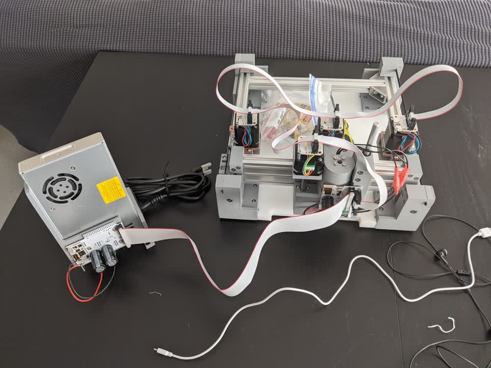
After all of that, though, I got it all built, and was ready to get going with the software!
Clank uses a micro-USB cable to connect to the laptop, and I had mistakenly used a micro-USB cable that was only for charging, and didn't have a data line. I fished another cable out of our electronics kit that does have a data line, and that solved the issues I was having trying to run the controller software. The cable that worked is really short, but luckily I had a USB-extension cable to allow for a bit more space on the desk.
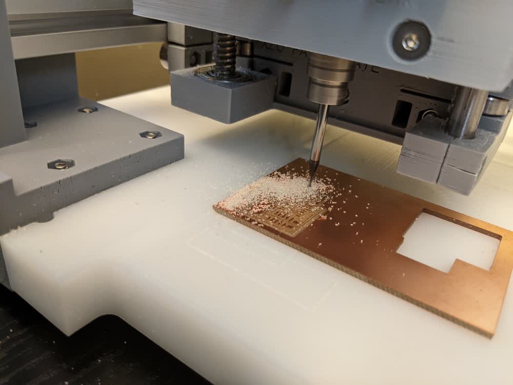
With Clank now working and moving, the first step is to face the bed. There's no guarantee that the bed is flat from the get-go, so we mill out a flat area relative to the machine with the 1/8" end mill. Everything seems to be working properly, so let's mill some stuff!
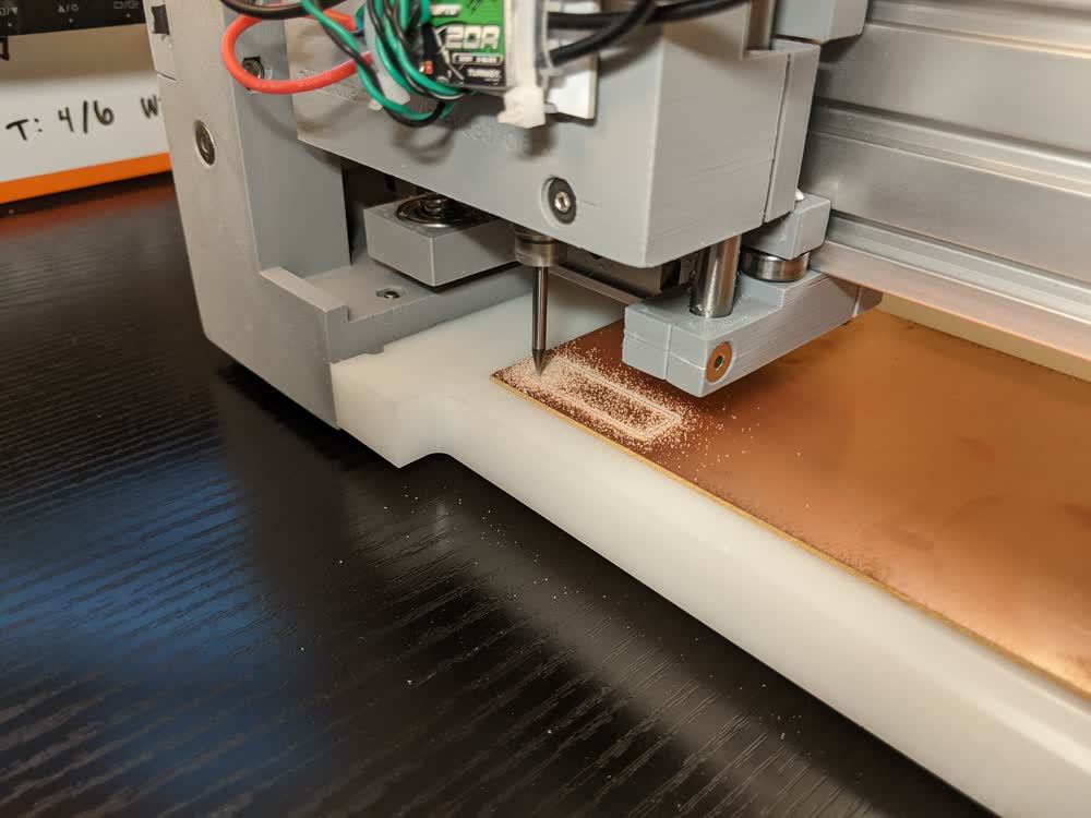
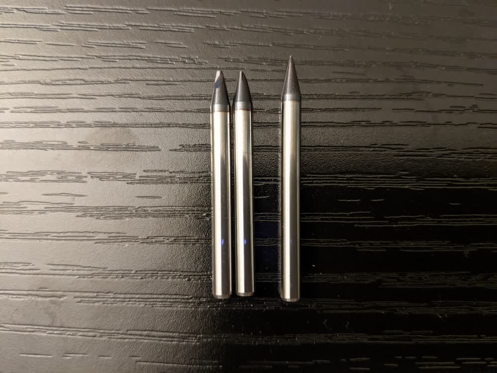
I wanted to test out how good the features and traces could be with the two different types of bits we were given for trace milling, the 1/64" bit with flutes, and the 0.01" engraving V-bit. I first tested the toolpath doing an air cut, then went ahead with the first cut.
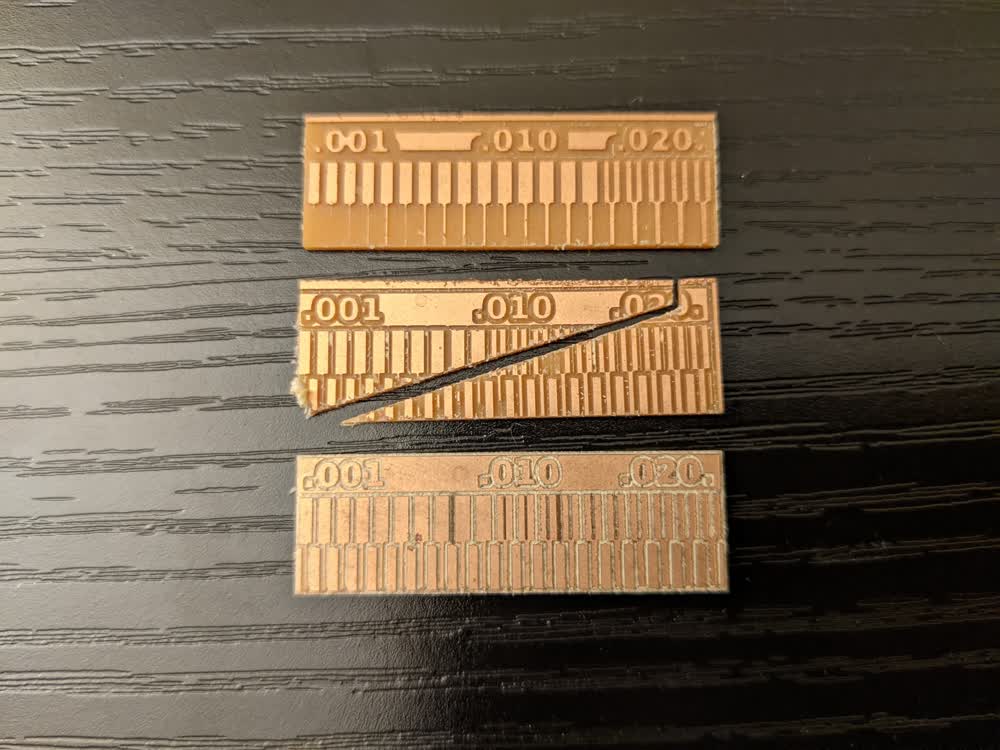
The top test cut is from the 1/64" end mill. It cut really cleanly, but had a difficult time with the smaller feature sizes. Some of the smaller traces were there once the cut was complete, but even after a bit of handling, they fell off. The middle test cut was from the V-bit, but something went wrong with the edge cut, and it gouged through the whole board (I think I hadn't zeroed it properly). Luckily, that didn't break the bit of my end mill. The bottom cut is the V-bit again, but with a successful cut out. The features are a lot better here. It got all of the smallest features just fine. There is quite a bit of white debris left where all of the cuts were made, and I think this is because the V-bit doesn't have flutes to pull the debris up and out of the cut channels. I later found out that this also was probably because I wasn't using an offset for the cuts other than the cut itself, and increasing to multiple offsets cleans it up nicely. With Clank fully working and succesfully cutting some nice features, it was time to mill an actual board!
With everything tested, I moved on to milling an actual PCB board. I used mods to convert PNGs to G-Code toolpaths for Clank, which worked very seamlessly. I used the following parameters for most of my cuts this week:
| End Mill | 1/64" | V-Bit | 1/32" (Edge Cut) |
|---|---|---|---|
| Tool Diameter (in) | 0.0156 | 0.01 | 0.0312 |
| Cut Depth (in) | 0.004 | 0.004 | 0.024 |
| Max Depth (in) | 0.004 | 0.004 | 0.072 |
| Offset Number | 4 | 4 | 1 |
| Cut Speed (mm/s) | 2.5 | 2.5 | 2.5 |
| Plunge Speed (mm/s) | 2.5 | 2.5 | 2.5 |
| Jog Speed (mm/s) | 10 | 10 | 10 |
| Jog Height (mm/s) | 2 | 2 | 2 |
| Spindle Speed (RPM) | 10000 | 11000 | 10000 |
The first board I milled was the hello.CMSIS-DAP.10.D11C board from this page. The 1/64" bit did a good job, but left some burring, and the pads were slightly smaller than with the engraving V-bit. It was then time to solder. I've got some experience with soldering, but not with such tiny footprints on components or with surface-mount soldering.
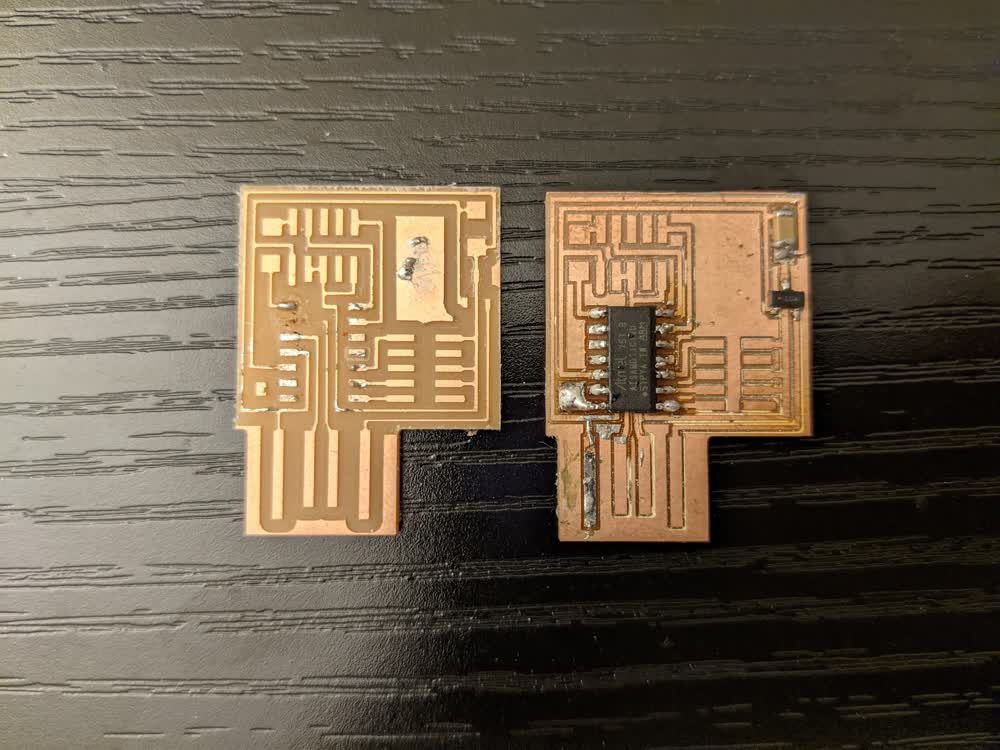
As is apparent, I didn't do a very great job. I ripped up one of the pads on accident, and I was having a pretty terrible time with everything else. I gobbed up way too much solder in places, and was just having a rough time. I also wasn't entirely sure on which components I needed for the board and eventually discovered that I didn't have everything I needed for that board in particular. So, I took a break and decided to start from scratch with a new and simpler board.
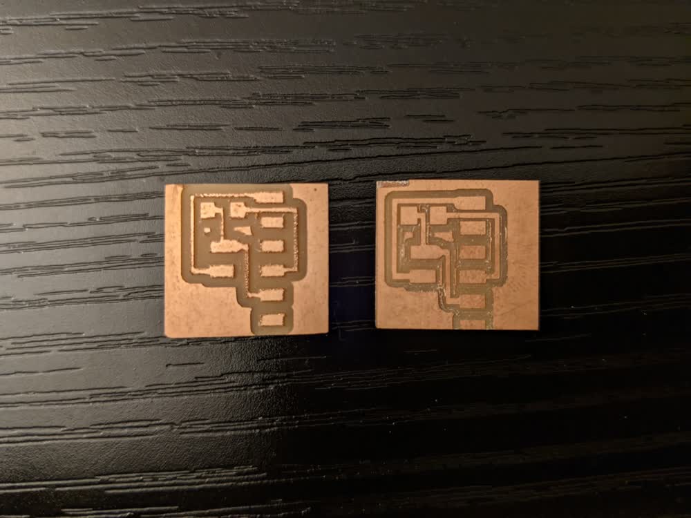
I decided to go with the hello.serial-UPDI.FT230X board that converts a serial signal to UPDI (also known as the FTDI-UPDI board). It was much simpler and I knew I had the correct components for it. I like testing the 1/64" bit and V-bits together for every board I make, so I did so again here. Again, the 1/64" end mill left a lot of burring, and the traces are smaller than with the V-bit. You can see that I increased the offset number here to 4 for the V-bit, as well, so it cleaned up very nicely and made some more room for soldering and helped avoid accidental solder bridges. You can see a bit of a weird notch in the corner of the V-bit board, and that's because I broke my endmill and had to try and manually zero it back to the appropriate place after getting a replacement.
In fact, I didn't just break my 1/32" edge cut end mill, I broke both of them making the exact same dumb mistake. Given, these events occurred on different days, but I broke my last one while trying to finish up this week's assignment... Of course... Essentially what happened is that I often press the 'x' key when jogging the spindle carriage around on Clank because it's faster. I even do this for the Z-axis sometimes. I was eyeballing it, and thought I had enough room to do one more big step down in Z, when I shouldn't have, and it plunged the bit straight into the stock and snapped the bit on the end mill. I vowed to not do that again, but I managed to do it, yet in a slightly different way. I had purposely kept track of how many times I had raised the Z assembly higher using the bigger step so that when I swapped bits, I could go down that many big steps without a problem. Well, I didn't take into account the fact that the engraving V-bits are several milimeters shorter than the 1/32" and 1/64" end mills, so I went down too far again, and was out of 1/32" end mills for my edge cuts. Luckily, I was able to run into the lab and get some replacements. I really hope it doesn't happen again, but I feel like I learned my lesson. I did break a 1/64" end mill, as well, but that was from a weird zeroing bug that I'm still not sure about. Needless to say, I am now very meticulous about jogging and zeroing the machine. Let's hope I don't get lazy with that.
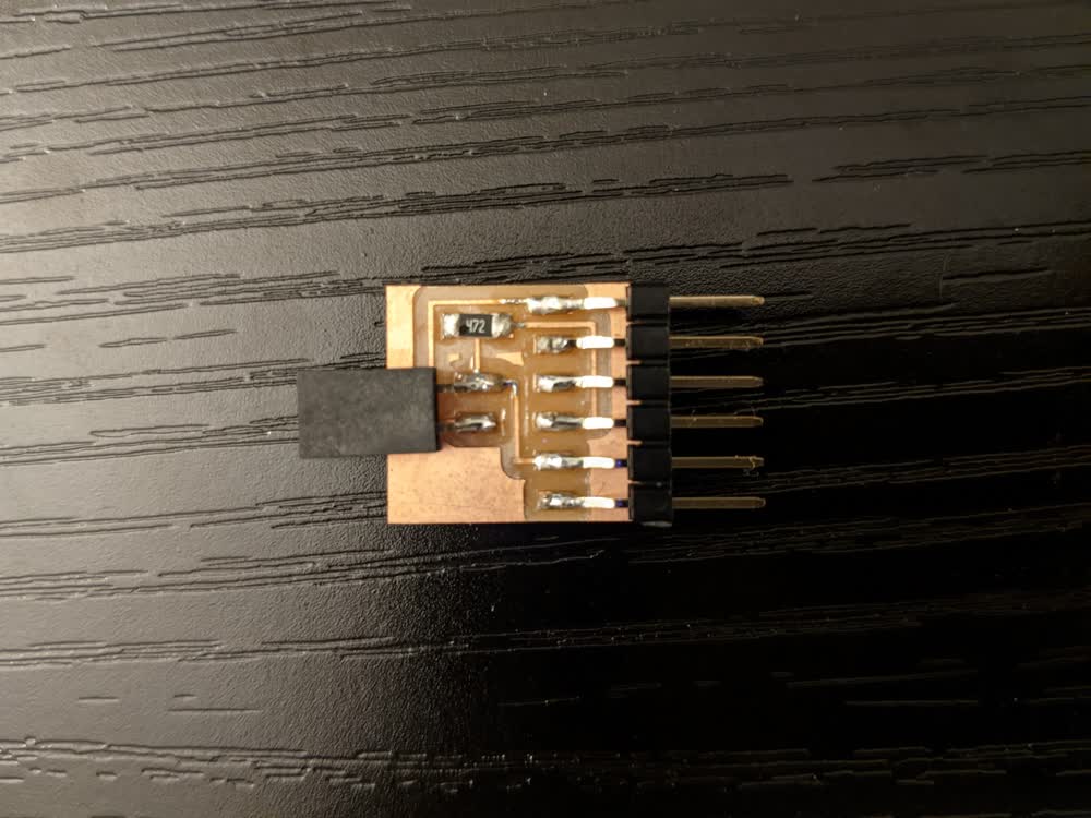
After all of that, though, I was able to mill a really good looking board again and soldered it. I had a much easier time with the soldering this time because I increased my temperature from 350°C to 400°C (we're using lead-free solder) and used the flat-end chisel tip instead of the pointed tip. Again, not a perfect soldering job, but it was much better than my first attempt, and with some practice, I'm bound to get better and better.
I'm really satisfied with everything I got to do this week, and I'm still so impressed by Clank. It was a blast to put together, and I'm really excited to make a lot of boards and to improve my soldering skills. I really need to take a deep dive into all of our components, though. I am not liking digging through all of these little bags and trying to decipher all of these letters and numbers that I just don't quite understand yet. I can definitely work on that, though. I'm excited to learn how to design our own boards next week!
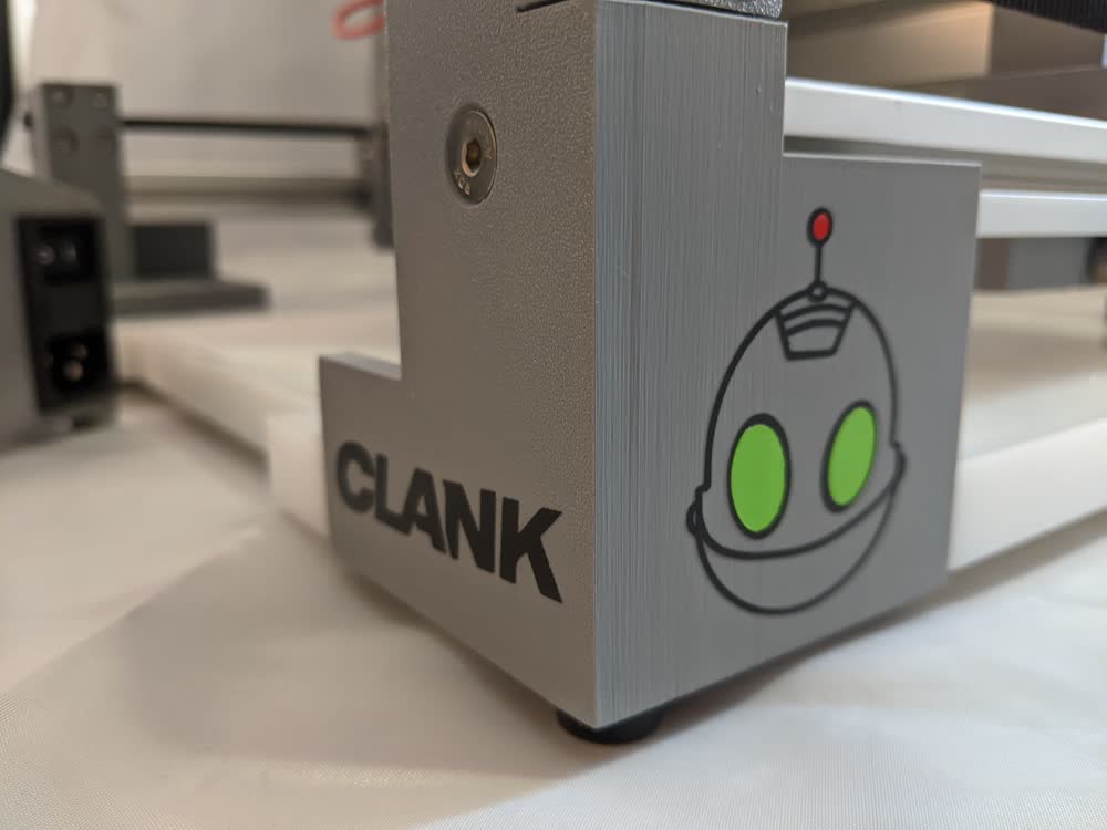
Finally, as the finishing touch to the week, I had to make sure that Clank's namesake was well represented, so using the design that my wife helped me make during the week we learned vinyl cut, I made little Clank name and face decals to complete the masterpiece! Again, I commend you, Jake, for the amazing machine you designed and provided us with!
I did not generate any new files for the week. All files I used were from the class website or other class resources.