Embedded Programming
We've designed and milled our own circuit boards, and now it's time to program them to do something! We learned in class about a lot of different microcontrollers, how they work, how we can communicate with them, and how we can get them to do what we want, in a variety of different ways. For this week's assignment, we were to read a datasheet for a microcontroller, then program a board to do something, with as many different programming languages/environments as we possibly could. The closest experience I have with directly programming a microcontroller "from scratch" is using Arduino for a variety of projects, so I thought I'd start small so I could really understand all of the details for what we did this week.
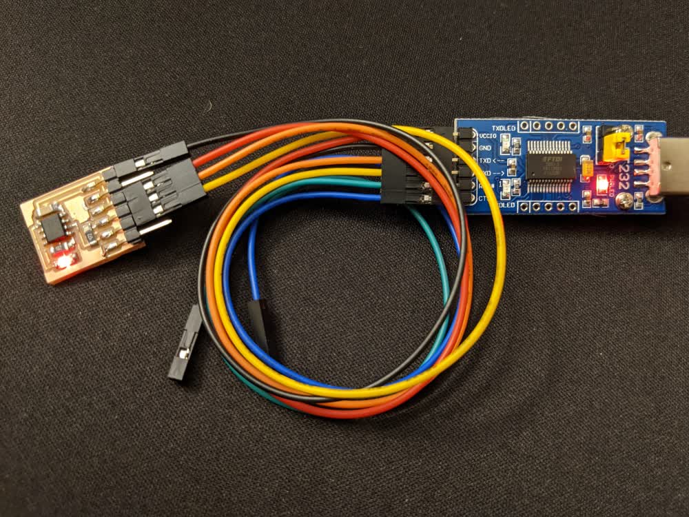
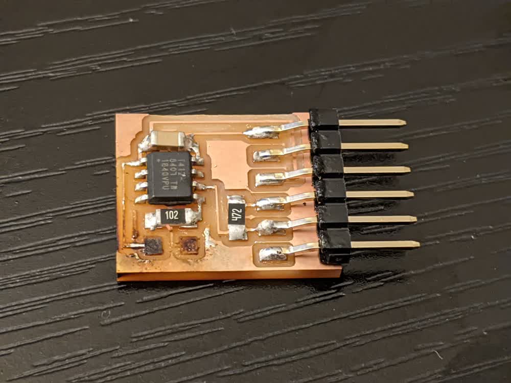
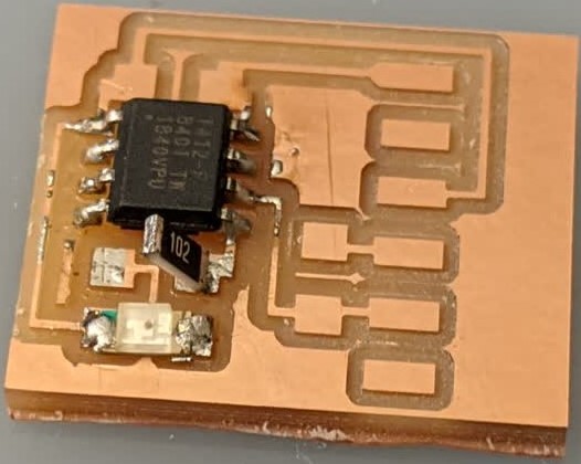
With that being said, I decided to create the hello.t412.blink board that uses an ATtiny412 chip to flash on and off an LED. Conveniently, the example board and code were already set up and ready to go, so I was able to jump straight into milling.
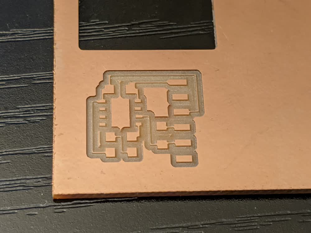
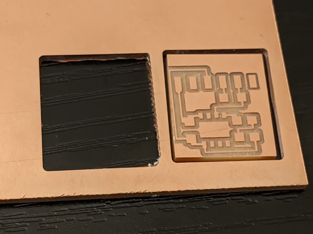
The first board I milled didn't turn out super great. I used a V-bit end mill, but I think I used a different one than I have been using the past few weeks, and it was a bit thicker in diameter, so the toolpath caused it to cut many of the pads and traces too small. I didn't bother cutting that one out of the copper sheet and swapped in the correct V-bit and milled everything just fine. Looks like I've got some fine-tuning I can do to determine the exact parameters for all of my different end mills.
After the board was milled, I got to soldering. I'm improving quite a bit at soldering such (AT)tiny components, and everything was working out well. I was having a really weird issue with my LED, though. Without the LED soldered yet, I was finding the proper direction with the multimeter (or so I thought), but when I soldered it down, I couldn't get it to light up any more with the multimeter. I thought that maybe I hadn't soldered it properly, so I kept trying to wick up the solder and remove the LED to check everything again. I ended up using the hot air gun to be able to remove the LED. Long story short, I kept repeating this cycle of checking to see if the LED was working, soldering, having the LED stop working, desoldering, etc. The hot air melted the clear coating that diffuses the LED light and from my excessive removals, I ended up just completely frying about three LEDs.
I didn't want to give up, so I reached out for some help, then tried to fix it myself again while I waited for a reply. Unfortunately, that final attempt was too much and I ended up burning/melting/ripping up the pads for the LED from the entire substrate. Looks like I need to mill a new board...
I probably should have taken a bit of a break at this point, because I was a little flustered, and wasn't fully paying attention with milling, so I had a few mishaps. First off, V-bits are sharp. When trying to remove one from the spindle collet, I stabbed my thumb a bit on accident. Not too bad, but it was a bit of a challenge to apply the bandaid with only one hand haha. With first aid addressed, back to milling. Typically when I mill, I'm good at babysitting my computer so nothing happens while milling is in progress. But this time, I just let it sit, and my computer fell asleep in the middle of the cut. Luckily, it was nearly done when it stalled, it just needed to mill out the offset traces of the very last pad. But I didn't realize that at the time, and moved on to try again. Everything went well on the traces cut, but when I was doing the edge cuts, I accidentally hit the back button on my mouse, which kicked me out of the Clank controller page, and when I went back in, it had refreshed, and it didn't make it quite all the way through the cut. The spindle was still spinning, though, and I could see the cut traces well enough, that I decided to try to finish that particularly perimeter cut manually by keeping the spindle activated and slowly moving along each edge. I didn't do too bad of a job! It didn't completely cut through the bottom layer of copper, but was very close to doing so, so all I had to do was take my box cutter and gently cut along the edges, which worked beautifully. Just in case I needed a backup board, I manually gave my best guess at where to start the edge cut for the very nearly finished board, and I pretty much nailed it! So that was pretty cool. It was quite the fiasco, especially because I was flustered the whole time, but I finally got it all milled, and was ready to try soldering again.
I decided to solder the LED first this time, which seemed to work before and after soldering it. I soldered the resistor and microcontroller, then tested the LED again. It wasn't working... Hmm... I tried some weird stuff, including raising one end of the resistor to see if the LED would work again with the resistor disconnected. I was really stumped. By this point, though, I had gotten a reply from Zach telling me that the LED was backwards (green dot means cathode, not anode).
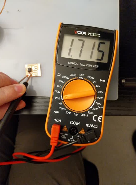
I was really confused because the multimeter was telling me that I had it in the correct orientation, so I thought that there must be a short somewhere else. But, then Zach kindly pointed out my mistake: my multimeter leads were not connected properly. *Facepalm* I felt like quite an idiot, but I was glad to finally figure out what was going on. Sure enough, fixing the leads of the multimeter and flipping the LED around made everything work correctly. I'm not going to lie, I feel kind of ashamed of these dumb mistakes because I should know better. But, I am learning (or relearning, in some cases), and I really need to work on this stuff when I am less stressed, tired, frustrated, hungry, or all of the above.
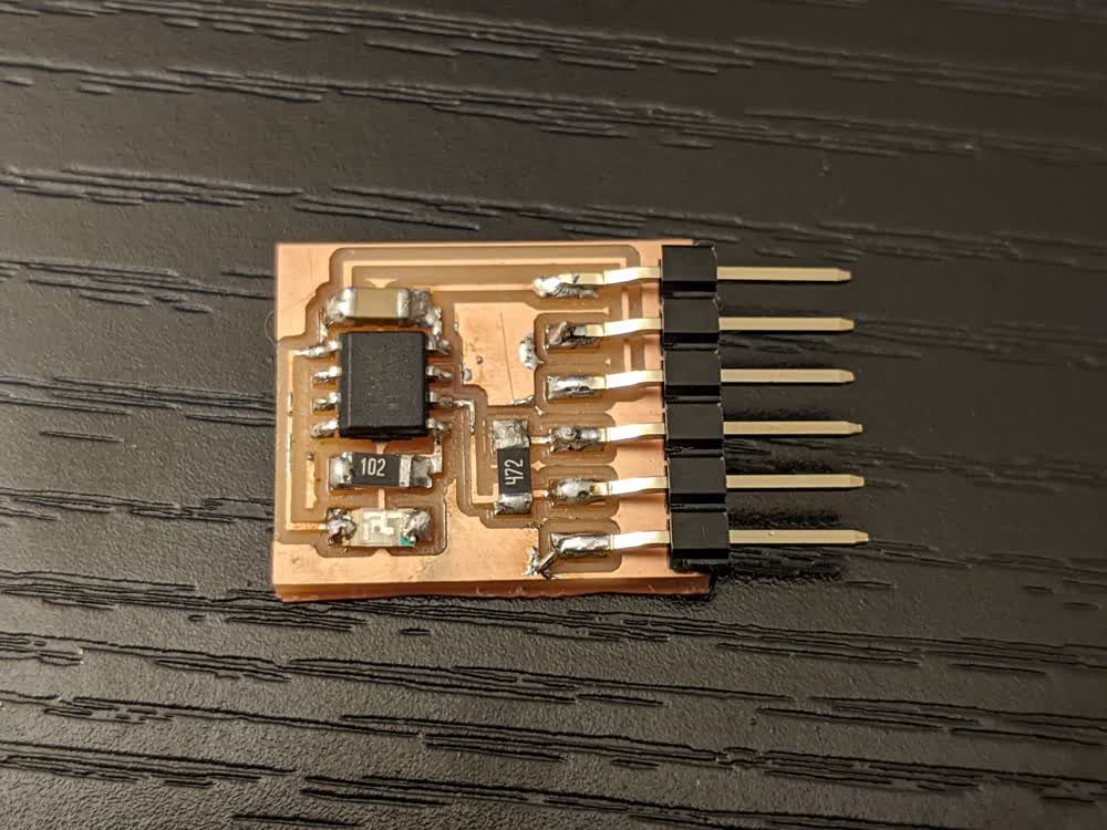
With the board finally soldered and everything working according to my (now correct) multimeter tests, it was time to start programming!
I was following along with a guide that Zach had compiled, but I will repeat the steps here for convenience. Note that some steps are different because I am using a Windows laptop, while Zach was using Linux for his guide.
First, I downloaded/installed the megaTinyCore library, as well as the latest version of the Arduino IDE. Once those were downloaded, I made sure to install the megaTinyCore package within the Arduino Board Manager. Now, I could select the "ATtiny412/402/212/202" board family for my "Board" and the "ATtiny412" for my "Chip". I left everything else as their default values.
Next, I saved Neil's hello.t412.blink.ino code to my own local files and opened it up in the Arduino IDE. I then clicked "Verify" to build the file. This creates all sorts of build files, that I didn't realize get created behind the scenes, including a program_name.ino.hex file. I made sure to locate that file using the debug terminal, then copied that .hex file into my own sketch directory.
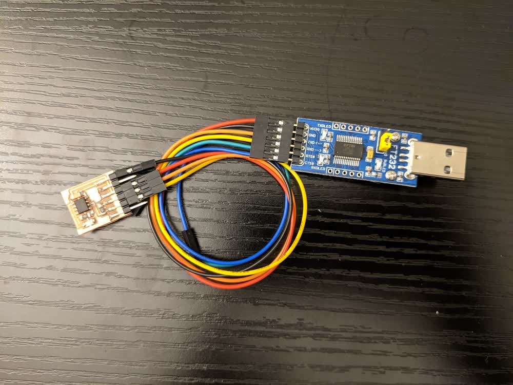
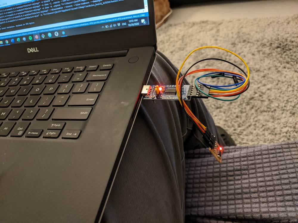
We were all given a Waveshare serial adapter board to program our own PCBs with, so I made sure to plug in some jumper cables between it and my own PCB, minding to make the proper connections. Once I had double checked that, I plugged it into my computer. I was expecting the LED on my own PCB to light up, but then I realized that it wasn't just a straight power to ground LED, but was triggered by one of the pins, which is what the code is meant to do.
I then cloned the pyupdi repository into a stable directory, and installed the proper dependancy packages using:
pip3 install intelhex pylint pyserial
I then hit a snag that I had kind of been secretly anticipating/dreading all week. We are supposed to use the following command to take the .hex file and actually program our microcontroller using the pyupdi script:
python3 ~/path/pyupdi.py -d chip_name -c /dev/ttyUSB0 -b 115200 -f file_name.ino.hex -v
On both Linux and Mac, I believe, /dev/ttyUSB0 is exactly written out under the "Port" section of the Arduino IDE, which represents the port that your USB device is plugged into. On Windows, however, that section will just say "COM X", where "X" is any number. For me, it says "COM 4". Now, you can't just replace /dev/ttyUSB0 with COM 4 or COM4. You still have to get the exact path right. I scoured the internet to figure out exactly how/where I could find that, but everything was extremely complicated, and just didn't seem like it would work. Again, the fact that I was tired and frustrated didn't make anything better, but it felt like I was pounding my head against the wall, and all for nothing.
However, I finally discovered that it is much simpler than it appears. Upon reading this article, there was something in there that related COM 4 directly to /dev/ttyS4, so I decided to enter that into the original line of code.
And hallelujah!!! It worked!
I obviously still have a ton to learn about why that works, but I really wish I would have known that beforehand. It seems really simple, and there can't be that few Windows users. I could have done some more research into past students that also used a Windows laptop, but it was satisfying to figure it out on my own.
As Neil shows in this video, you can change the build path for your hex files, which I brought to be much closer to the rest of the sketches, which resulted in my final line of executable code from the Arudino sketch directory to be:
python3 ../../pyupdi/updi/pyupdi.py -d tiny412 -c /dev/ttyS4 -b 115200 -f ../build/hello.t412.blink.ino.hex -v
This made it possible to run the exact same line of code after I made any changes to the original .ino file and clicked build.
I then tried blinking the light at different intervals, just to be sure that my edits were truly working.
I was very happy to get all of this working and felt good that I had been able to figure out some seemingly insignificant, yet majorly time-consuming issues I had. Unfortunately, they were so time-consuming that I didn't get a chance to experiment too much with other programming languages and environments. However, I feel a lot more confident in the fundamentals of what I was able to do, and I should be able to leverage my previous programming experience to enable me to program more and more complex things. I still want to learn more about the programmer, and I really want to make my own, but for now, I'm happy with what I accomplished, and I will absolutely need to incorporate these skills to succesfully complete my final project.
I did not generate any new files for this week. All files used to mill and program came from Neil.