Output Devices
This week, we learned about a variety of output devices that we could control with our microcontrollers to make some cool stuff happen. We learned about simple things like LEDs, displays, video/audio, motors, and even some cool shape memory and soft robotics. So many intriguing options, but it was time to put my head down and really get to work on my final project at this point, so I started thinking about what I could easily integrate from this week into that project.

My first line of thought was to test out the speaker and microphone that we were provided with in our kits. I've only ever used a simple buzzer speaker in an Arduino project before, where I used some really fun code that I had found here, then used my own sheet music reading skills to figure out the math for the timing, as well as the pitches, to play some fun little cinematic themes, like The Avengers theme, The Legend of Zelda theme, and The Bridge of Khazad Dum from The Lord of the Rings. I hadn't ever used a microphone that I hooked up/soldered myself, though, especially such a tiny one.
Unfortunately, at this point in the class, I was starting to be in a rush preparing everything for the final project, and had a bit of a hurdle to figure out with the audio portion of my project: it's one thing to play a variety of pitches to make little songs, but I needed the capability to play and record full-on voice messages, store them to my microcontroller or circuit somewhere, then upload or download the recordings wirelessly. That whole combination seemed liked quite the large task to tackle straight on, so I opted for something a little more simple, but still vital to the project. Before I stop talking about the audio portion of the project, though, I'll have you know that the solution I decided on was to use a Raspberry Pi Zero W to wirelessly interface between the two devices and pass the messages back and forth. I was told that there was probably a speaker and microphone module that could be easily integrated into a Pi that I should just plan on using once I had figured out the networking between the microcontroller and Raspberry Pi, as well as between the two devices themselves.
Anyway, I decided to focus my efforts on making an array of LEDs that would be strung behind the different block holders in the final project so that whichever block/person had a new message waiting would signal that by lighting an LED over it. Because there are five of these block holders, and the fact that they're fairly spaced out, it didn't make sense to just design one really long PCB that would go across the back of them. So, I started to think aobut how I was going to get the proper signals to the proper LED locations. I didn't want to just get a bunch of really long wire to go from each pin on the microcontroller to each individual location, but wanted to make my own sort of bus routing system to get all of the proper signals across in a streamlined process.
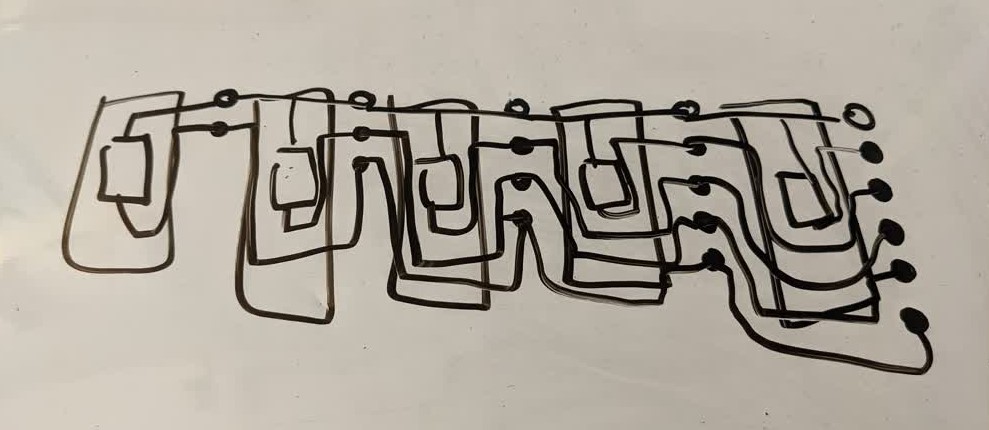
After a bit of brainstorming and reworking, I finally figured out a good solution after sketching a diagram out on my whiteboard. I could have the power line go across each of the LEDs just fine, but I would need to get all of the signal lines to go around the LED and resistor, but still route to the correct LED. Now that I had a good idea of what it would look like, I was able to move on to the KiCad design.
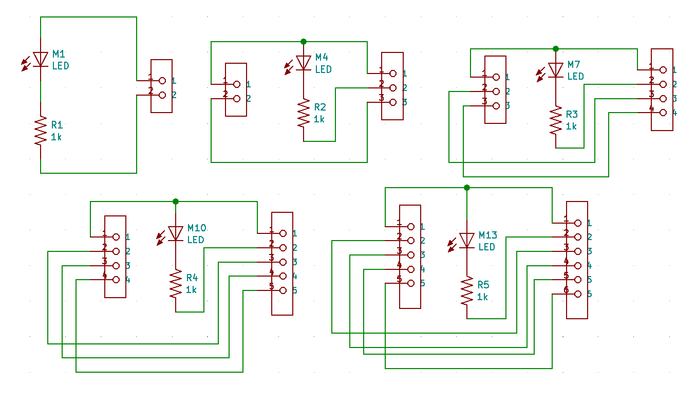
I put all five boards in the same design and had everything go right in a row, with the empty gaps between boards representing where the wires would connect the boards. This seemed pretty straightforward, so I moved on to the PCB layout.
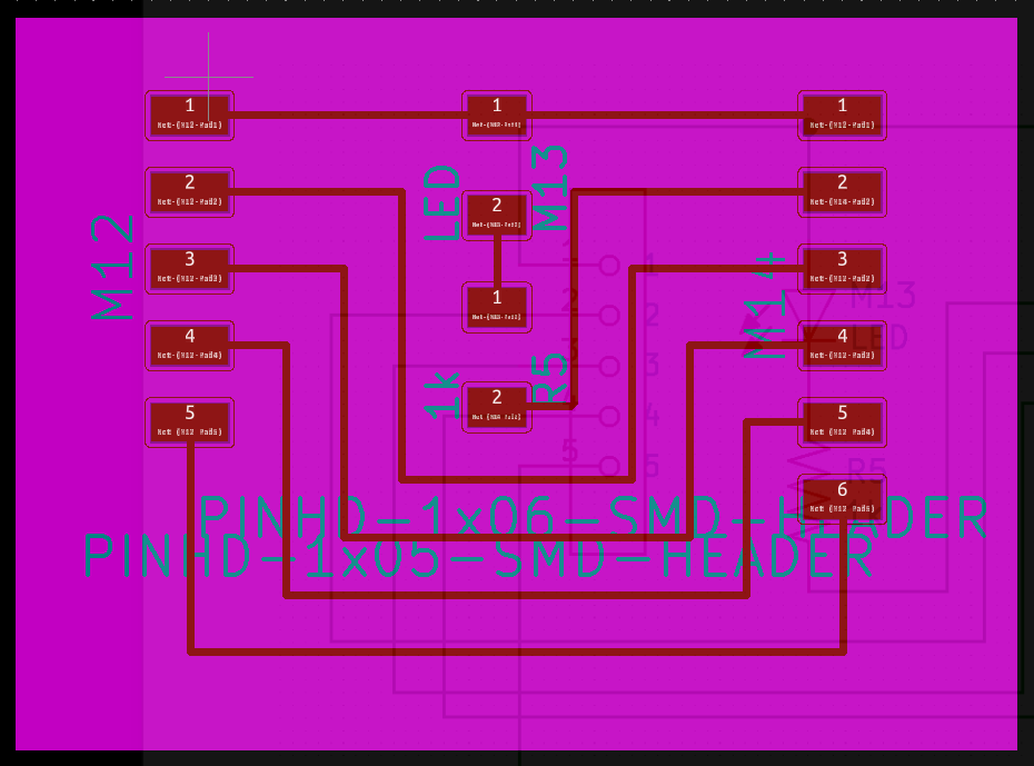
There were a lot of components to untangle here, and I had a decent layout for each of the boards, but then it dawned on me how nice it would be if each of the boards were uniform in terms of dimension and placement of the components. So I started from the board with the most pads first. As I completed the design I was happy with, I realized that there wasn't actually a need to make the rest of the boards and have to worry about milling five different boards. I could use this same board design over and over, I would just need to reduce the amount of header pins that I soldered to the boards. The dimensions of the boards were just right that I could fit two per 4" by 2.7" copper clad FR-4 boards that I had to mill the PCBs with. So, I just duplicated that design and got to milling.
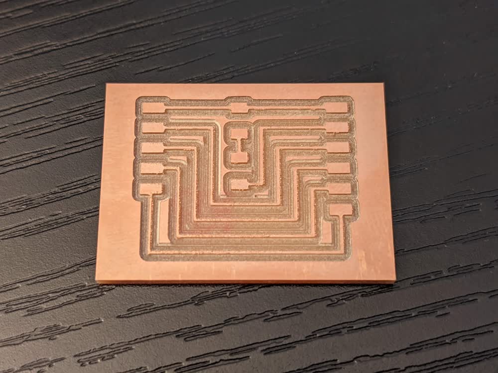
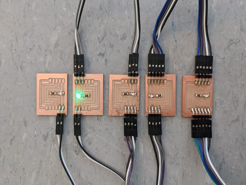
The milling went well, but my engraving bit caused some burring, but I could just scrape that away with my metal straight edge rule in different directions, and while it looks a little worn, the PCB has a smooth finish to the touch, and the copper itself wasn't harmed too bad.
Once they were all soldered up, I just daisy chained them together with the jumper wires, and it was time to get testing with some code. Because I was already working on integration with the rest of my final project, I was able to use the magnetic sensors in my reader board to toggle which of the LEDs turned on or not.
Overall, I was able to access each of the LEDs pretty easily, and I experimented a bit with the code to determine the easiest way to write the LEDs. I was going to use bytes and bitwise operators to write everything, but it had been a while since I really used that in some code, so I opted to set array values and have the LEDs written according to the array of highs or lows. It worked well, and I got the leds attached to the block holders and everything lit up quite nicely. Be sure to check my final project page to see everything integrated together.
Here are the KiCad files for my board:
- led_board.zip - All KiCad Files in a ZIP Folder