Networking and Interfaces

Week 10

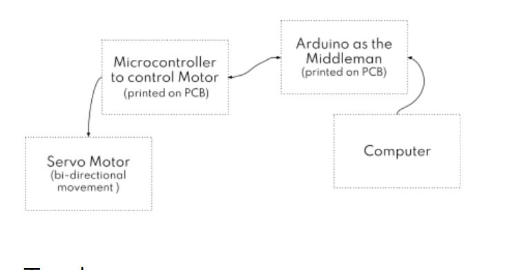
This project is a culmination of a series of smaller iterations that started with building a micro-controller on a PCB board and culminated with driving a servo motor to control a pump. My project demonstrates how pressing a button by a user triggers a communication between computers, in this case, I2C, to control a motor action.

Tools

SOFTWARE: Arduino library, Processing

HARDWARE: Arduino, Othermill to print the PCBs, wires, breadboard, servo motor

OVERVIEW OF SYSTEM DIAGRAM

Inspirations

PEOPLE WHOSE WORK I USED AS REFERENCE

I referred to a ton of sites, videos and blogs to understand the concepts. Some people whose documentation was specifically useful include Jordy, Cody and Alejandro.


Steps to Set up

  • This was my first step playing with Processing so it was an adventure learning how to write code on it. The following steps will give you an idea of what happened as I set everything up.
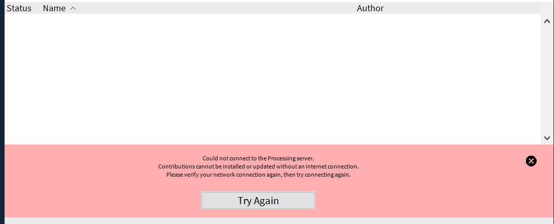
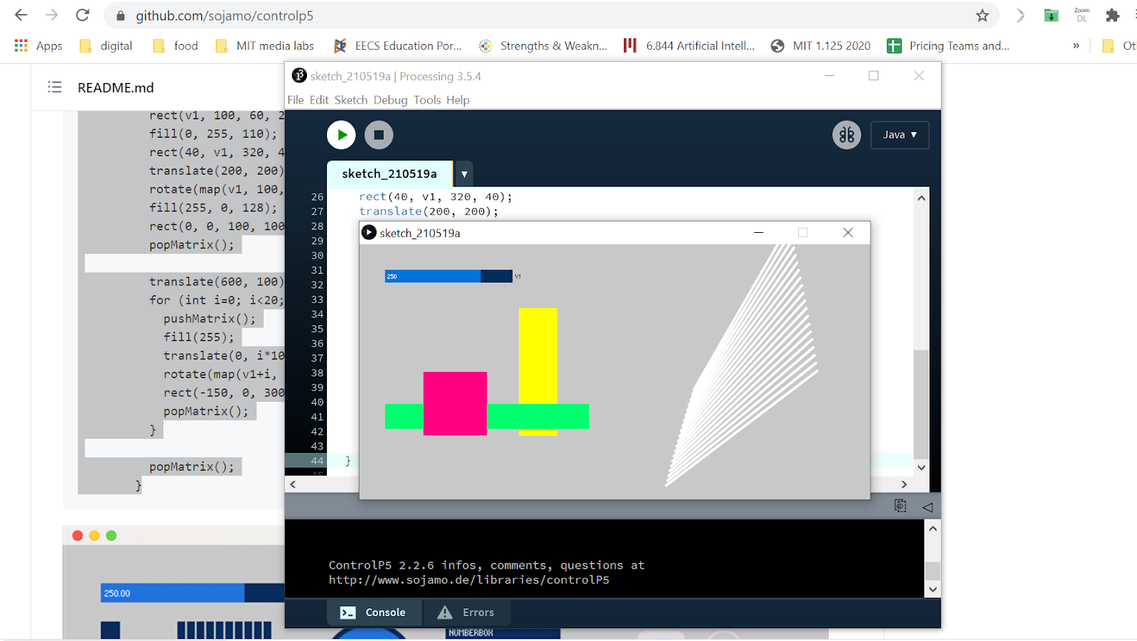
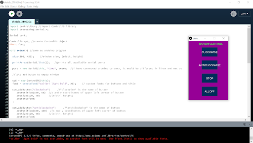
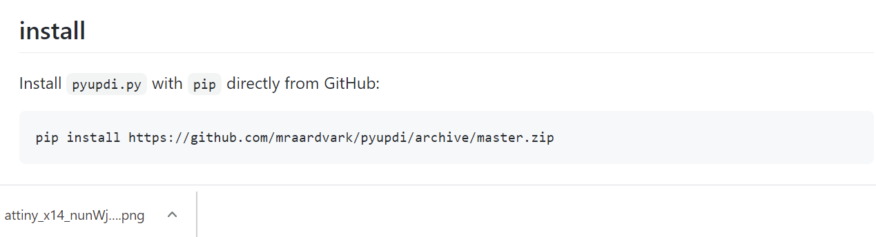
    Issues with installing Processing: After I downloaded the Processing software, I ran into an error that prevented me from installing the libraries. So I referred to this link and followed all the instructions, including installing the serial library and control p5.


  • Debugging step 2: Anthony helped me debug the issues by deactivating my antivirus package and adding Processing to the Firewalls allowed in the system.
  • System diagram: I created a schema to understand the system map. The image below explains the data exchange between the Arduino and Computer along with the circuit.


  • Code in action: Links for reference [1], [2]. Other examples: [3], [4]


  • Processing code diagrams


  • Things I learned and struggled with: I learned how to change the sizes of the screen and so on. I followed the tutorial pretty closely to first conceptually understand what the assignment required and then tried to replicate the same on my PCB. However, I ran into several issues that grossly expanded the time it should have taken to finish this assignment. I struggled with figuring out everything from installing python and pip again to erasing the files on the tiny to rewriting them. In all this, I reversed the wires of the motor and that fried the bridge 😫 and the tiny which I had to resolder only to run into UPDI initialisation errors over and over again.
  • UPDI issues: The problems I kept running into were not new, nor unfamiliar - the UPDI initialisation failed several times. I had to redownload python since the weird issue of the device folder kept occurring repeatedly. Pip was not installed in the right place. It's so intriguing, however. I haven’t touched any of these settings since when they were first working but everything has issues now and one has to debug from the beginning again - every single time. Many times during this course, I felt like giving up. And it's because I was emotionally exhausted that I was making way more silly errors like reversing the pins that would burn the H-bridge as well as the Tiny.
  • Alternate options


  • The code that worked! The code below demonstrates the logic to rotate the motor in a certain direction and stop based on user input.


  • Fixing the loose ends: The remaining work included the setting up the motor, solder parts and build the circuit for the motor. I did encounter one more error for loading the code but I later managed to debug it.

  • List of helpful commands
  • Command for GitBash to run the code:
    $ python pyupdi.py -d tiny1614 -c COM9 -b 115200 -f /C:/Users/jkrit/OneDrive/Documents/Arduino/build/motor_2.ino.hex
  • Installing PIP: 5
  • Installing Python: 5
  • Alternate command when the above ones didn’t work:
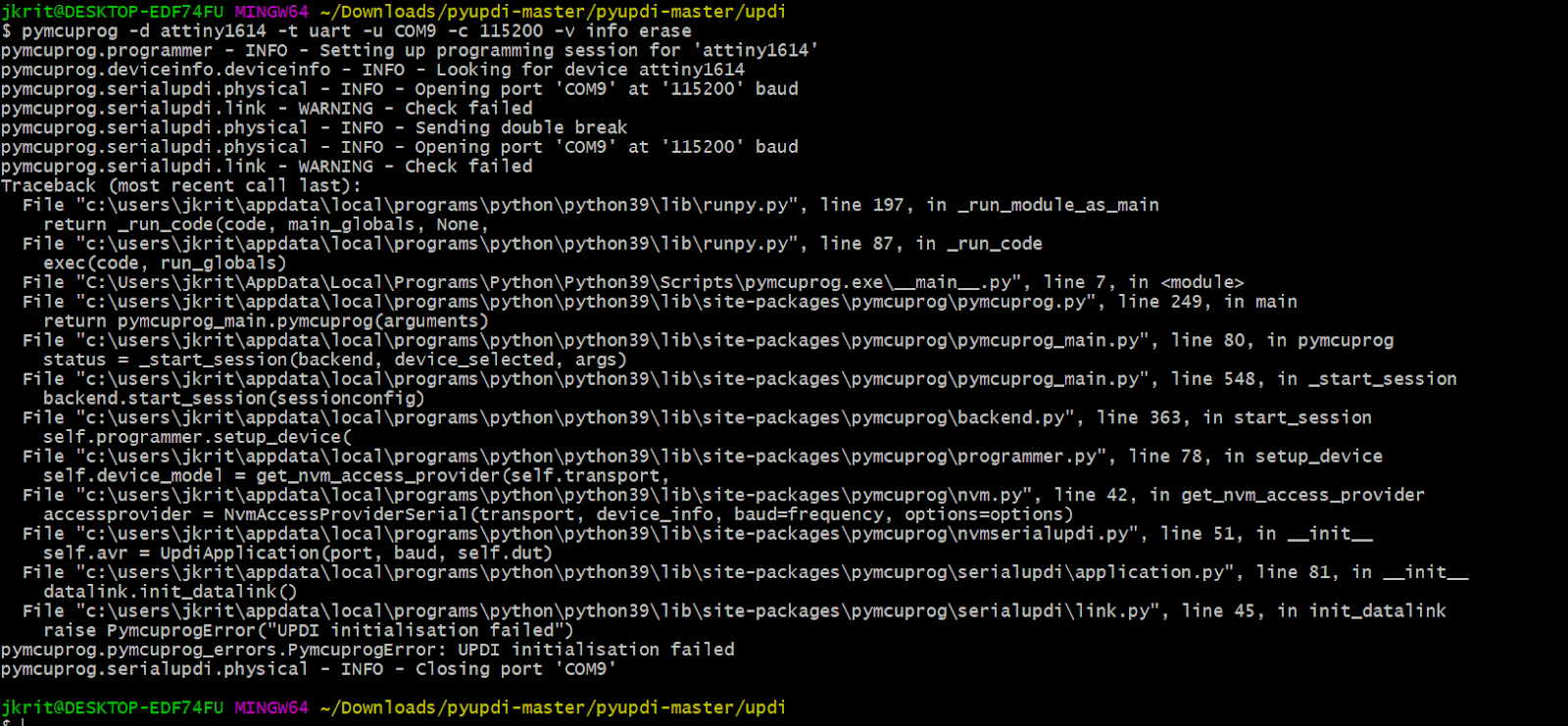
    - pymcuprog -d attiny1614 -t uart -u COM9 -c 115200 -v info erase
    - $ pymcuprog -d attiny1614 -t uart -u COM9 -c 115200 -v info write -f /C/Users/jkrit/OneDrive/Documents/Arduino/build/motor_2.ino.hex


  • And the code that tied it all together:
    pymcuprog -d your_processor -t uart -u your_port -c your_baud_rate -v info write -f your_hex_file $ pymcuprog -d attiny1614 -t uart -u COM9 -c 115200 -v info write -f
    C:/Users/jkrit/OneDrive/Documents/Arduino/motor_2/motor_2.ino.t1614.20c0.u5V.mD0.hex
  • Motor GUI:
    $ pymcuprog -d attiny1614 -t uart -u COM9 -c 115200 -v info write -f C:/Users/jkrit/OneDrive/Documents/Arduino/build/motorgui.ino.hex
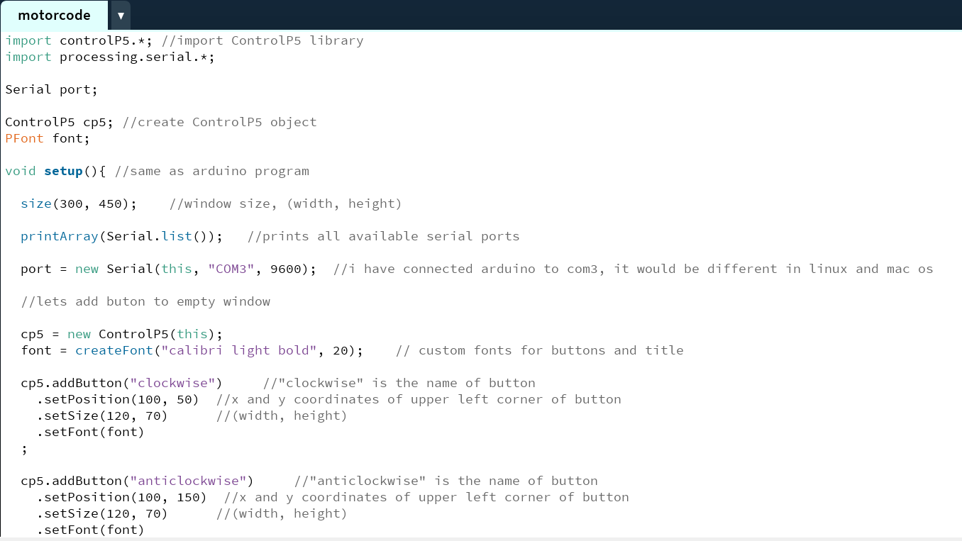
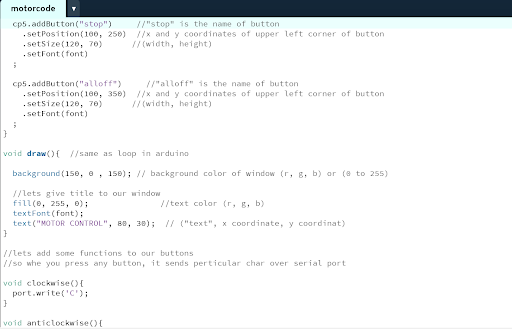
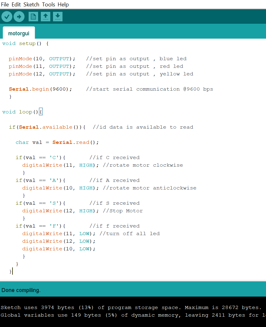
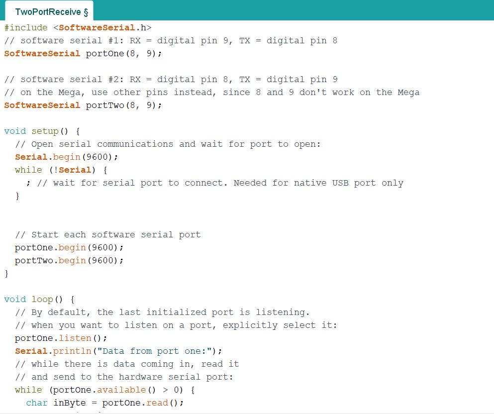
    here's an image of the code for networking: Here's the code for the motor:


    Here's the video of the system working:
  • Collaborators & Mentors Anthony Pennes