Week 9: Output Devices
For this week, our assignment is to use an output device. I decided to design a circuit to communicate with an OLED display, as I'll be using that in my final project.
I'm slowly starting to feel more confident about electronics design, so this design/cut/stuff/program process went much more smoothly than the past few weeks, except for a small hiccup in the footprint design for the OLED (explained below).
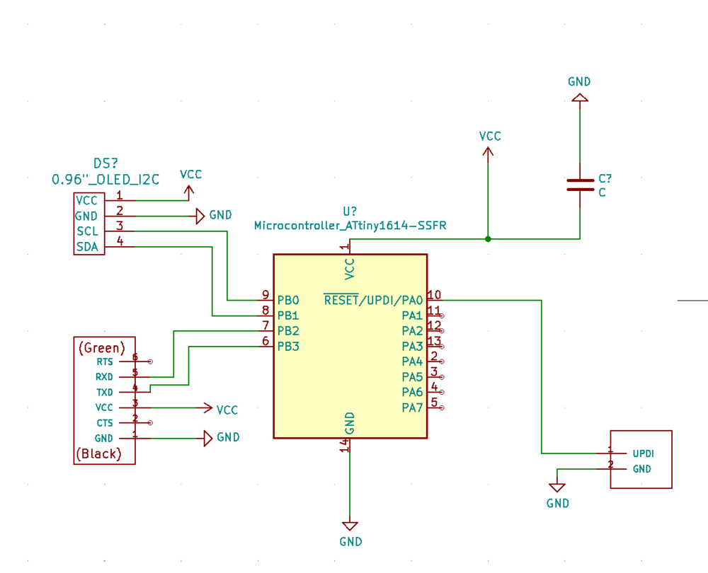
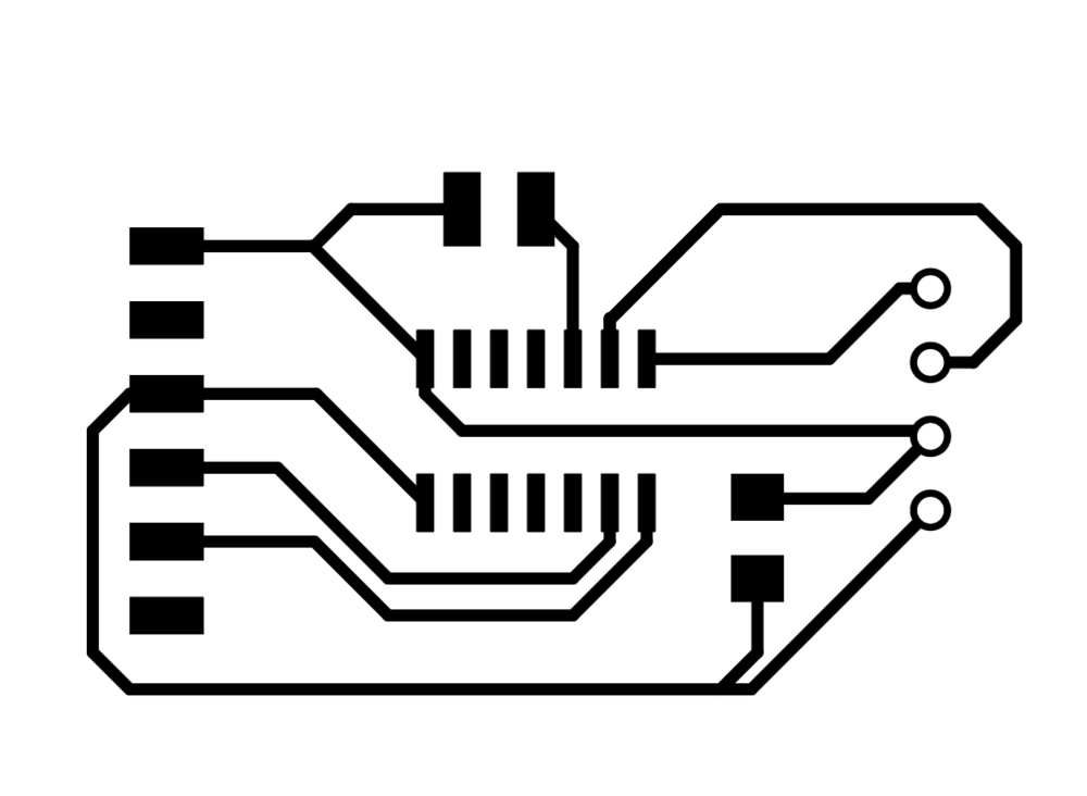
I started with a schematic - I had used the 1614 tiny in my week 7 project, so I was familiar with the pinout for that, and it all went smoothly until I realized that I didn't have the schematic or footprint info for the OLED display. I did a little digging and found a prior student's site where he had created a footprint library for the OLED I was using. (Site Here) *IMPORTANT NOTE* Be warned, the VCC and GND pins are reversed on this footprint, so don't do what I did and have to reroute them!!!
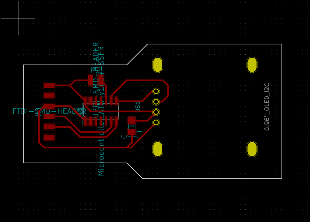
The footprint made holes for the display but I just wanted a steady surface to solder it to, so I changed them from open holes to closed squares in Illustrator.
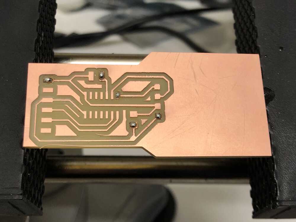
Board cut on the clank - it's working reliably now as long as I tighten the top screws before each cut.
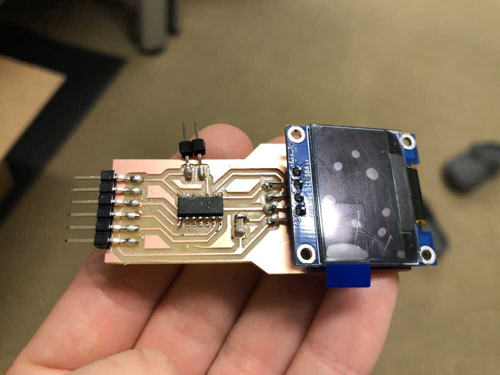
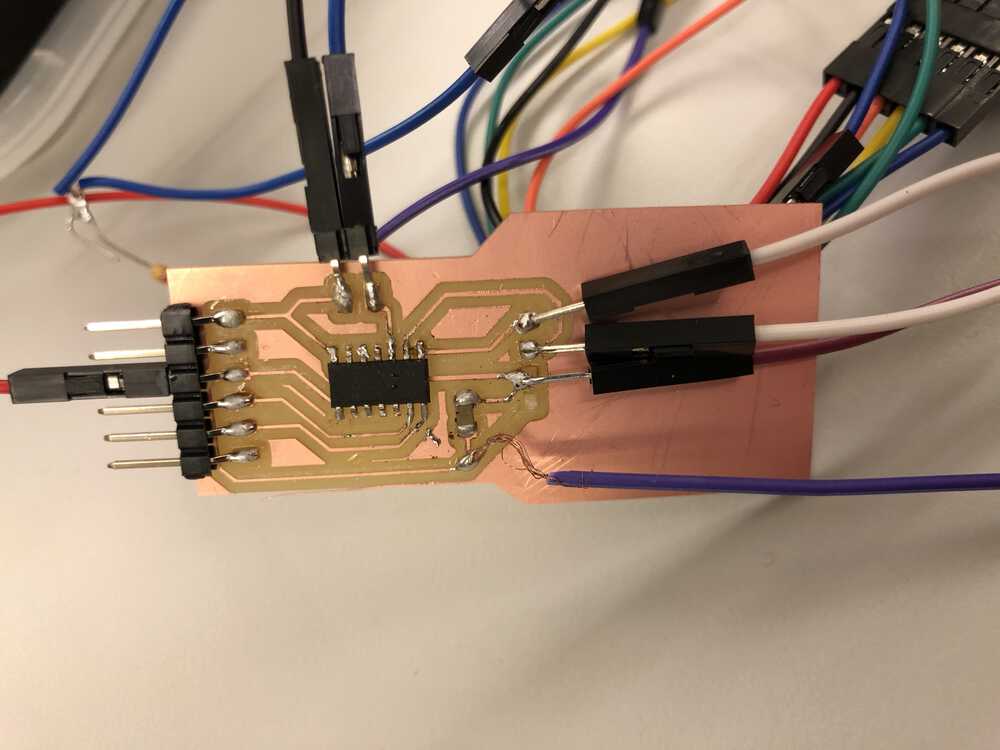
Here is how I originally soldered the board before Anthony helped me realize that the VCC and GND pins were switched
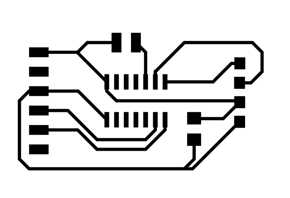
And after the slightly janky job I did in rerouting...
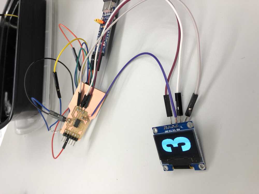
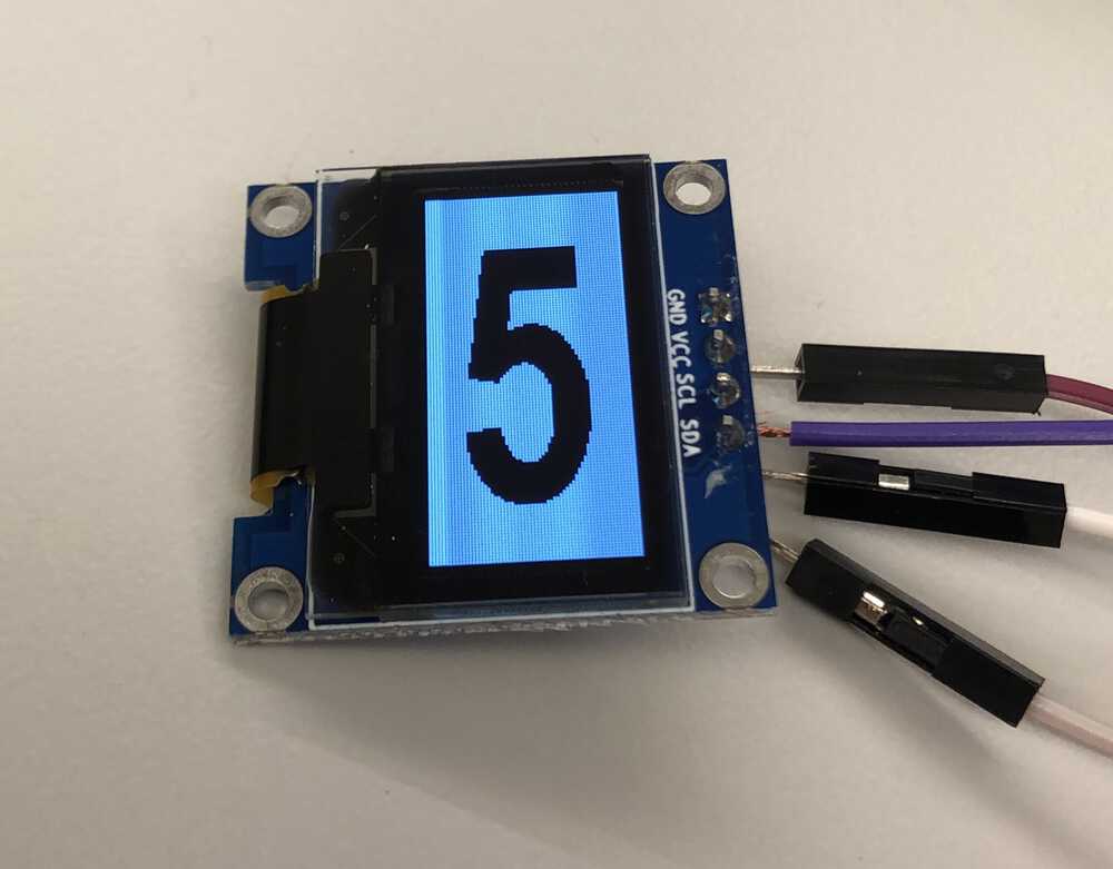
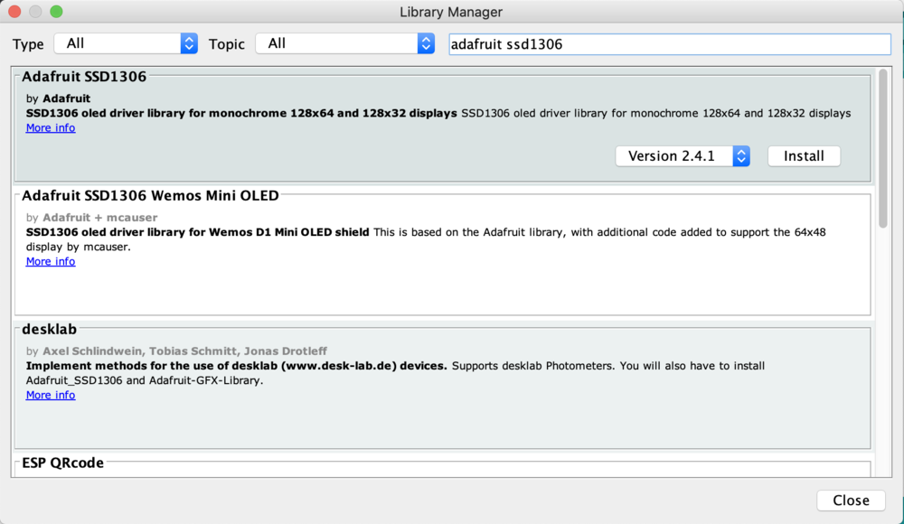
I then installed the Arduino graphics library that you can use to talk to this type of OLED, and Created a bitmap of a few numbers to test
A few sample images below!