Home
Project 10- Outputs
This week I made the electronics to control LEDs
Goals
Class Assignment:
- Add an output to a microcontroller board
Things I took away from this week
- i love circuits
- conductive thread is very fickle
The ~Process~
- Designing the circuitry to drive LEDs
This assignment I wanted to work on something for my final project. This week I also got a concussion (despite using my stool, I found a way) so this week's assignment took me quite a bit (a lot) longer to finish.
For my final project I wanted to have LEDs all along the cape, twinkling or with some other effect. To do this, I decided I'd have multiple channels of LEDs coming out from the microcontroller.
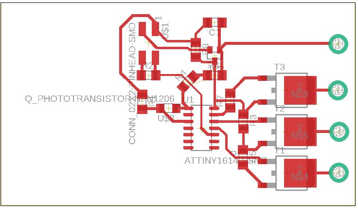
I designed another board in Eagle. For the final project I'd need a battery connection, a linear regulator, the MOSFETs, and holes to tie the conductive thread to. To get this effect I used the 2x2 connector and another part in Eagle that had a hole circumscribed by a circular trace. I had a bit of trouble with the MOSFETs. They all had to be tied to the same ground and go to screwpads. I asked Anthony and he suggested I use 0 ohm resistors. I had to use a bunch, but finally got a design that would mill.
- Cutting and stuffing the board
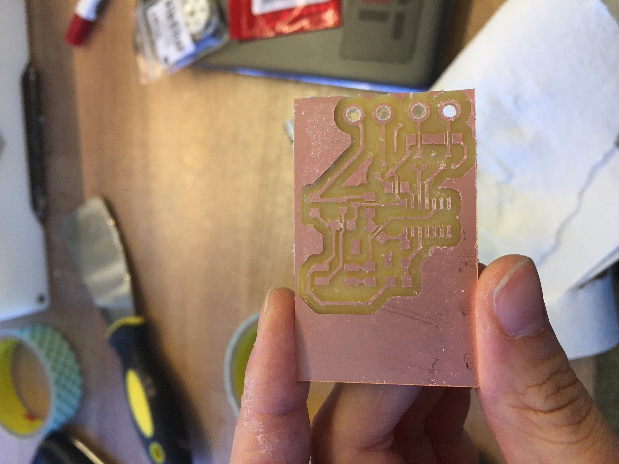
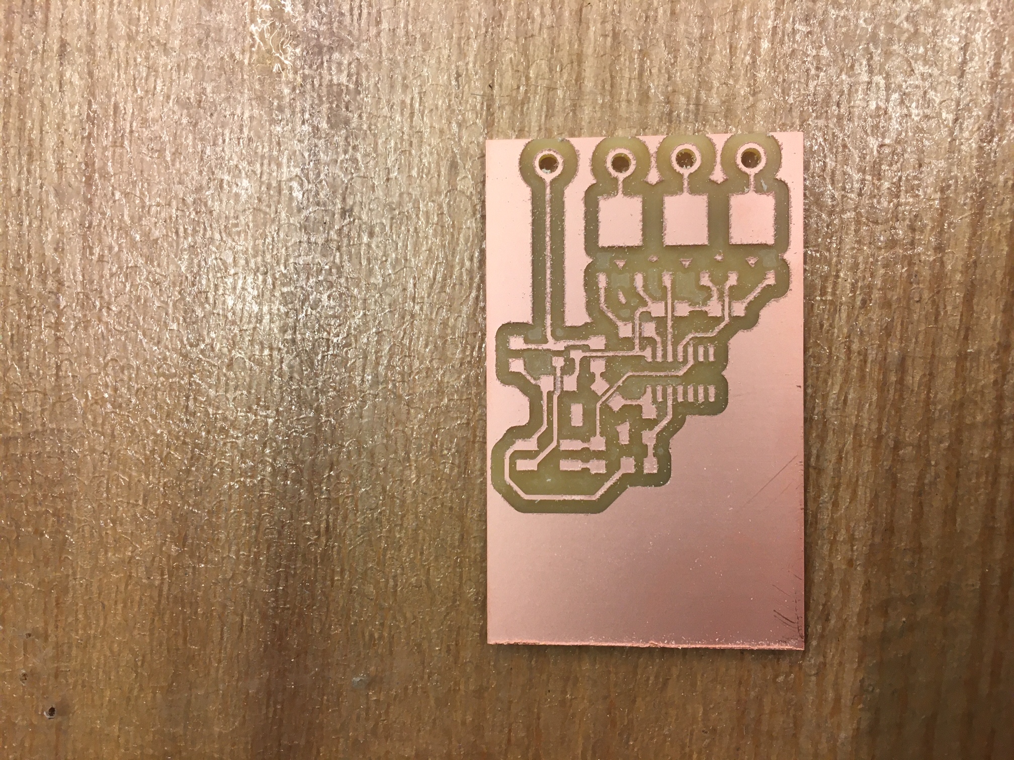
I took my board to the mill in EDS and cut away. I cut out the PCB, with several failed cuts. The first cut I used the wrong footprint for the MOSFETs (even after Anthony warned me to use the big one, whoops). The second had a problem with the tape. The middle of this one wasn't taped down properly, so it kept liftin up leading to super thin traces. The third one was very ugly, for unknown reasons, and I also forgot to add more offsets to prevent the different LED channels from shorting. The fourth time was the charm, and I quickly went to solder things up.
 Once everything was soldered up I tried to test the simple blink code with a single LED. But when trying to run the pyupdi script, the UPDI initialization failed. I looked over the schematic and the populated PCB and lo and behold my battery connector was backwards. The phototransistor was also backwards. I re-worked these things and tried again. The light sensor was working properly! Alas, there was still a problem. I had forgotten to solder the UPDI pin on the ATTiny. Since the trace went through the microcontroller, I didn'y notice that I had to solder it. I fixed this, then ran into yet another failed initialization. I was worried that the battery was dead, so I checked that the microcontroller was getting power. It was, but it kept reading 4 V rather than 5 V that the linear regulator was supposed to output. Upon closer inspection, you could notice that there was a small bubble on the linear regulator. This might explain the smoke that I saw earlier when I first connected the battery backwards. I replaced the regulator, and *still* got another error. I used the multimeter to check power, gnd, and UPDI. All of them were consistent with what I would expect, so I replaced the microcontroller. Success at last! Now it was time to test the conductive thread with the LEDs.
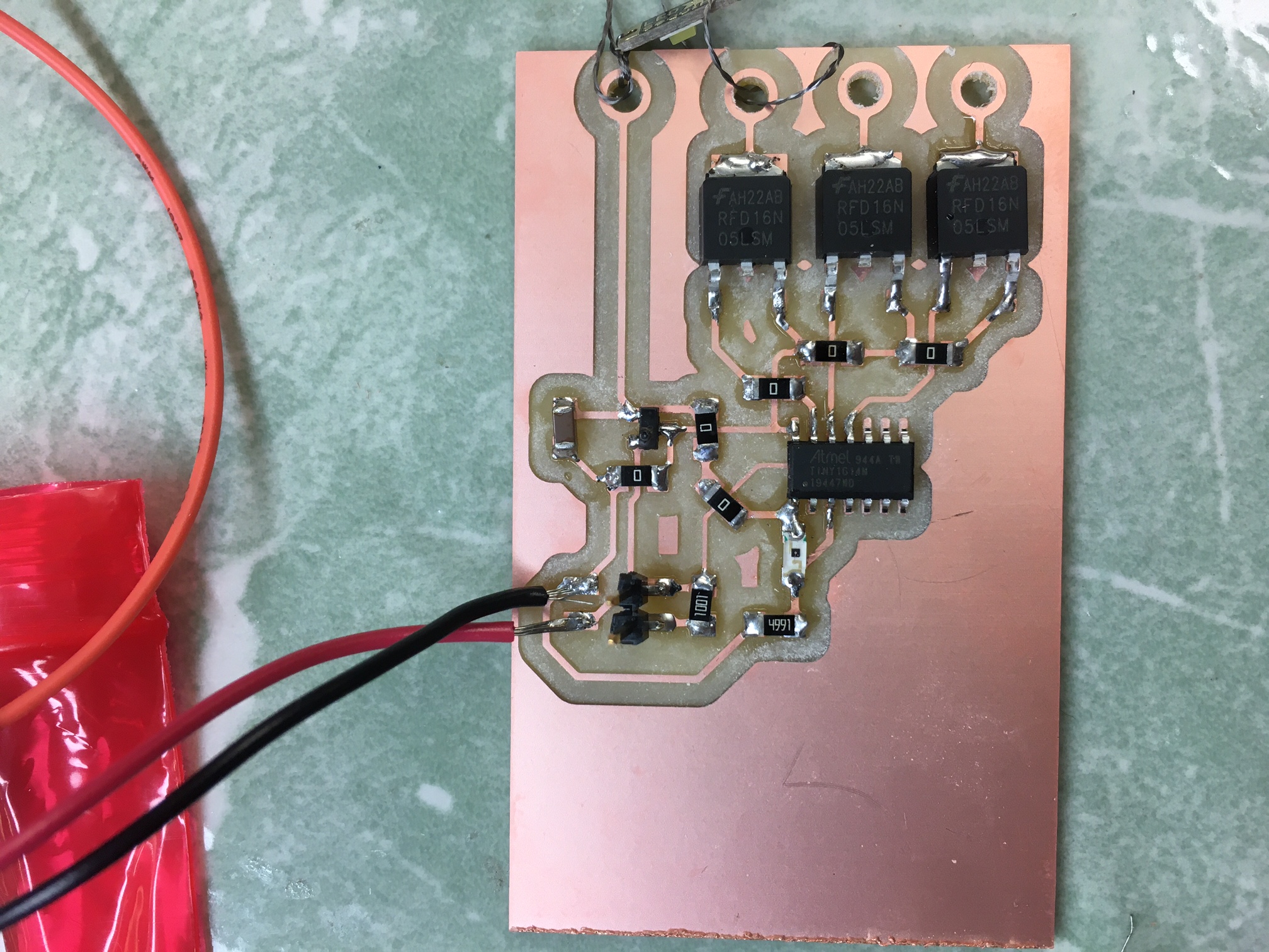 (Note: In hindsight, I definitely could have made these sewable LEDs: all it was is a surface-mount LED matched with a 100 ohm resistor with little pads like the ones I made on the main board.)
- Making the outputs do something
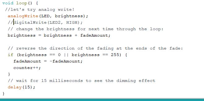
I had a couple of different effects that I wanted to try out for the final project: a simple on/off blinking, varying the brightness based on light level, and some PWM blinking based on the light level. After sewing some LEDs onto my cape, I wanted to try using the analogWrite function to see if I could see the difference between a regular blink code. This is the code I used :
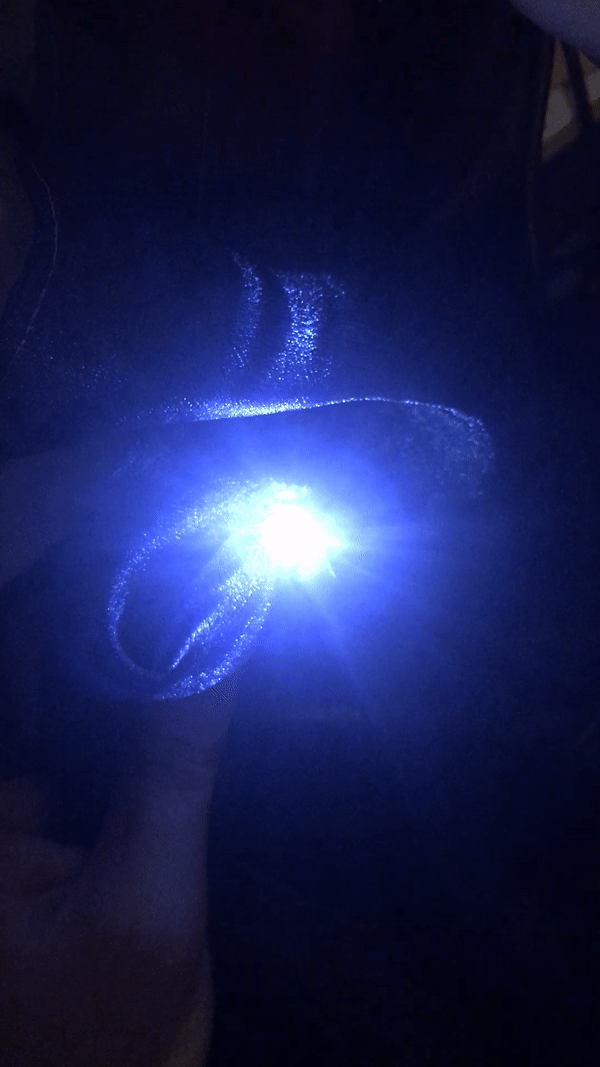
 And this is what it looked like on the LEDs. It doesn't look that much different than the blinkcode, unfortunately, but I think it still looks nice.
 I also tried out a couple of different effects, check out the final project page and the video there!