Home
Project 9- Inputs
This week I made a light level sensor
Goals
Class Assignment:
- Add a sensor to a microcontroller board
- Read analog inputs
Things I took away from this week
- i love circuits
- applying things i've learned is fun
The ~Process~
- Designing a ligh level sensor
The first part of this week's assignment was to add a sensor to the microcontroller board. I figured this was the perfect time to make something for my final project. For my final project I'm going to need a light level sensor to determine the behavior of the LEDs that'll be on the dress. For this circuit, I came up with a simple circuit to give a higher voltage the higher the light level.
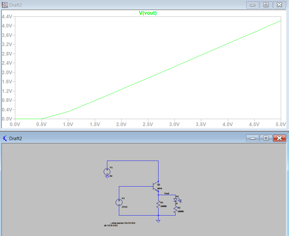
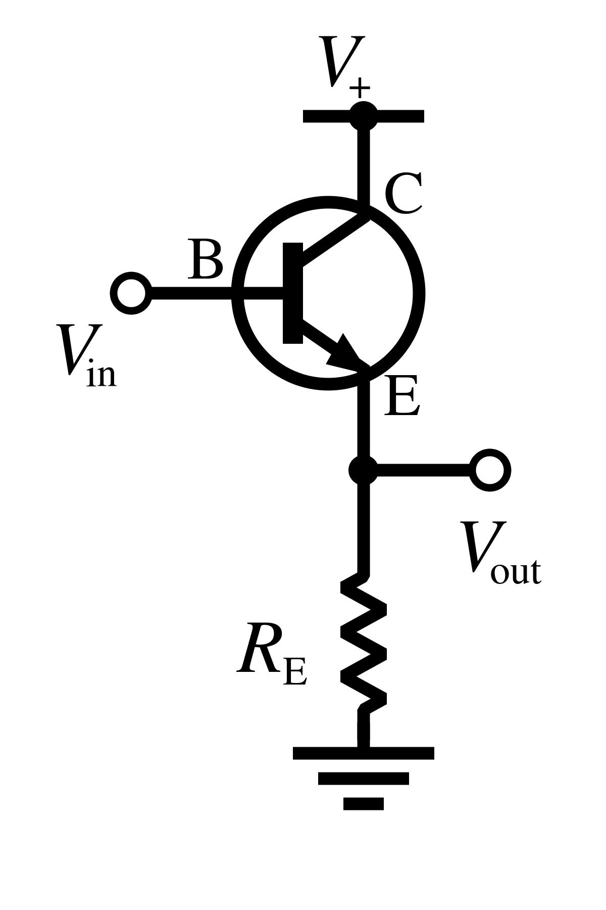 This configuration is known as a common-collector amplifier. The general idea is that as the voltage at the base increases. The voltage difference between the base and the emitter is constant, so the voltage at the emitter (the output) increases as well. For a phototransistor, the voltage at the base increases for higher light levels. This way, we get a higher output voltage for higher light levels. I spent *way* too long trying to figure out how to simulate a phototransistor in ltspice, but Anthony recommended that it wasn't worth the trouble. Here is a simulation of how a traditional NPN in a common-collector configuration behaves for increasing base voltage.
- Cutting and characterizing the sensor
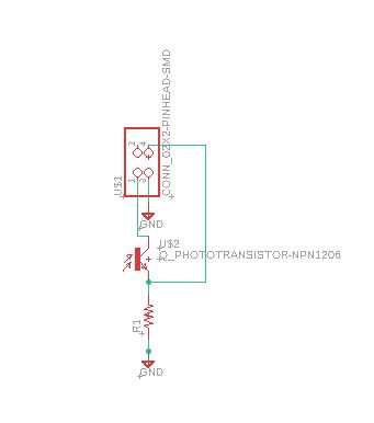
Once I had a grasp of how the sensor would behave and what a reasonable range of resistor values were, I made the schematic and did the PCB layout for the sensor. I started off with a simple board that could be connected to the helloworld board or another future board.
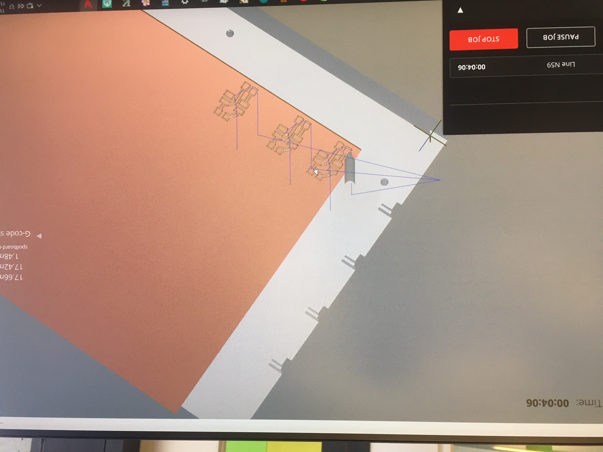
 I cut this out using the mill in EDS. To save time, I put three copies of the board onto the CAM. This is what that looked like:
 Once cut, i stuffed the board, careful to get the correct orientation for the phototransistor. While soldering one of the phototransistors, I heard a little buzz and was scared that I busted it. However, it seemed to work fine.
- characterizing the sensors and determining best values for R
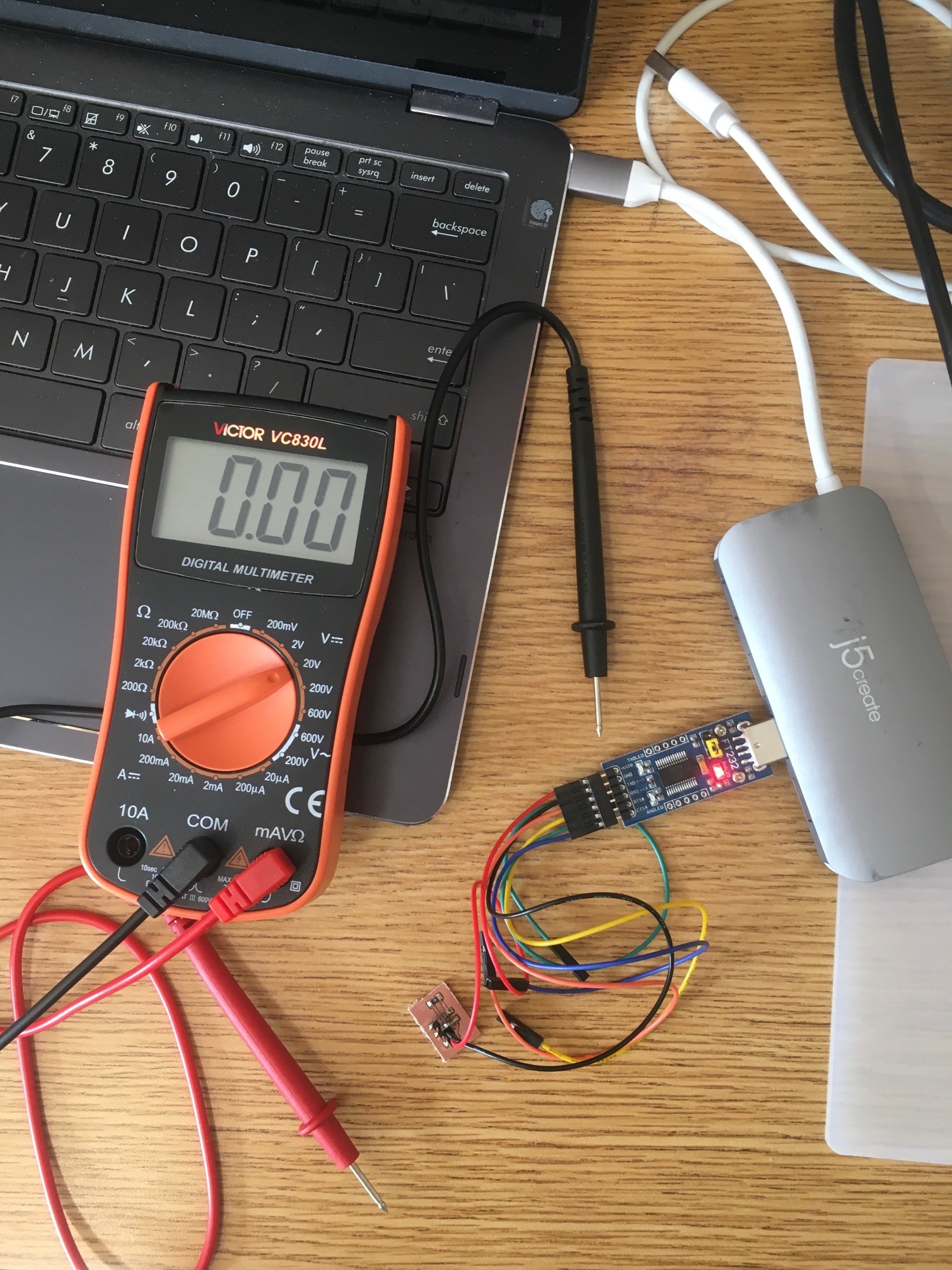
Once everything was connected, I tested two different values of R; 1k and 4.7k ohms. I also wanted to try 10k but the kit didn't come with that value. If I had realized that earlier, I would've made a (close to) 10k by putting 2 4.7k resistors in series. This would require me to add another component to the PCB and recut. Will have to do this at another point anyways, but likely won't be able to before Wednesday.
For the two sensors that I had i tested the output voltage of the sensor with different light levels. I tested in a dark room, in a lit room with the window closed, and in a lit room with my curtains opened when it was sunny, around 2 pm. Both sensors behaved as expected: they had higher output voltages for higher levels of light. However, the output voltage was really low. I think this is likely due to a characteristic that I ignored for the characterization: the value of Vce. This is the voltage drop between the collector and the emitter. This voltage peaks can go up to 4 V. So when I had an input voltage of about 3.5 volts from the USB adapter, the voltage at the emitter is really low. To test this, I will need to make a new board. This board needs to have similar operating conditions as the sensor that will be used in the final project. So it needs to be powered with a higher voltage that goes through the regulator, and then gets read by the microcontroller. However, this exercise provided useful information on the resistor values for the sensor. i will likely use the 4.7k resistor for the final light level sensor.
- Interpreting the data with the microcontroller
An important part of the project will depend on how the microcontroller "sees" the input value from the light sensor. I will have to take the output from the light sensor and send it to a ADC (Analog to Digital Converter) pin on the microcontroller. I am concerned with how sensitive the microcontroller is to the changes in the output voltage and at what point it detects a 'HIGH' signal. This will determine whether or not I will need to add an amplifier to increase the output voltage from the light sensor. I'm still having trouble communicating with the microcontroller and will update this page once I am able to read data from the microcontroller.
(Delayed) Update! So for outputs week I had a board with both inputs and outputs. I designed a new board with the light sensor, microcontroller, and connections to the outputs. I connected the board to the programmer and opened up the serial monitor. I ran this code:
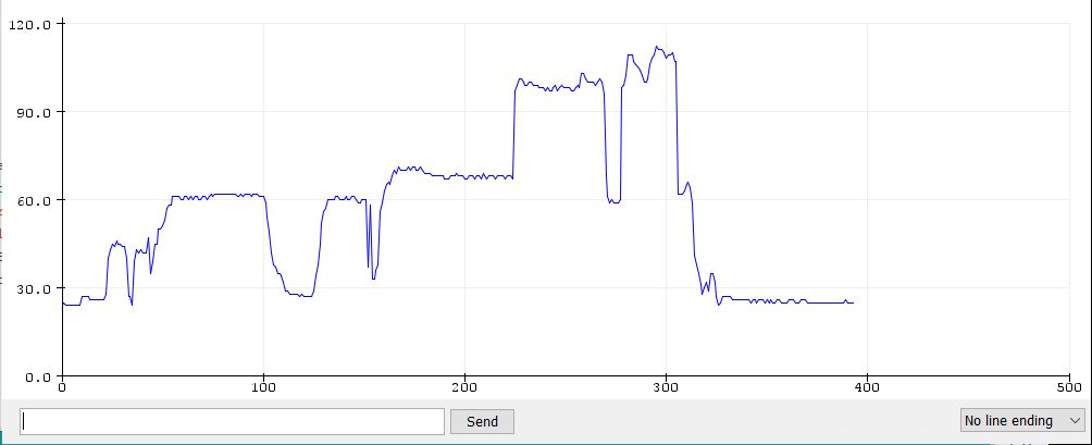
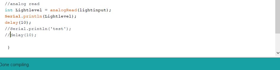 The analogRead function in arduino takes inputs from analog pins and turns them into an integer (0-1023 for a 10 bit ADC) with a resolution of max voltage/# of bits (so like 4.9 mV for a 10-bit). The ATTing1614 has a 10 bit DAC that gets inputs from pins 2-5, 8-9, and 11-13. From this, I don't think I'll be needing an amplifier.This is the output I got, which makes sense considering the voltages I measured with the simplified sensor.