final project: internal mechanisms prototyping
November 14, 2020
Before I started using Fusion360, I drew out where my components would lie inside of my housing.
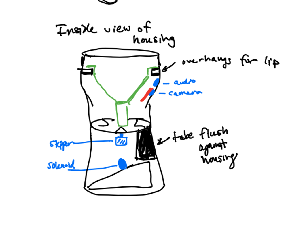
Internal sketch of my housing
treat
Looking on the treat website, the treats were advertised to be around 0.5” in width and there was no information on height. To get the right specifications for my treat to better design my mechanisms, I asked my mom to do some measurements of the Charlee Bear treats we had at home. I got that each treat was around 3/4" in diameter and 1/4" in height. I also used Fusion to design some 3/4" by 1/4" treats that I will use to test my mechanisms.
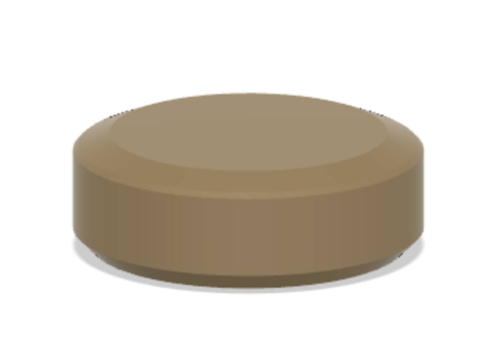
3D printed treat with correct dimensions
solenoid launching base
Now that I’ve set my sights on using a solenoid for my launching mechanism, I needed to design something to hold the solenoid upright at an angle. This is important because we want the screw or whatever metal object I am putting in the solenoid to return flush against the front of the solenoid. Putting it at an angle will allow gravity to do its work and pull my launching component back into place. If I left the solenoid flat, then the screw would never go back into the solenoid and would always be in the “launched” state. The figure below describes what I am describing.
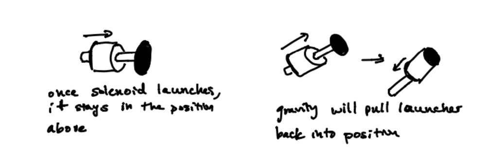
Sketch outlining how to re-load the solenoid
I started by setting some arbitrary parameters so my design could be parametric. Once I got
I made a divot on the top face of my base for my solenoid to fit into. This is helpful since the shape of my solenoid is a circular shape. Additionally, I created a lip in both directions that would hold the solenoid in place. Below is my initial design for the launcher holder I had in mind.
I made a divot on the top face of my base for my solenoid to fit into. This is helpful since the shape of my solenoid is a circular shape. Additionally, I created a lip in both directions that would hold the solenoid in place. Below is my initial design for the launcher holder I had in mind.
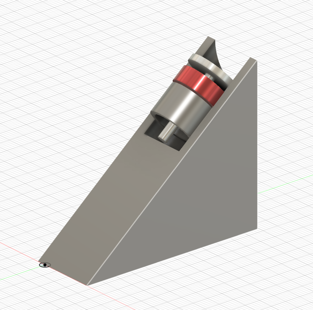
CAD for solenoid housing
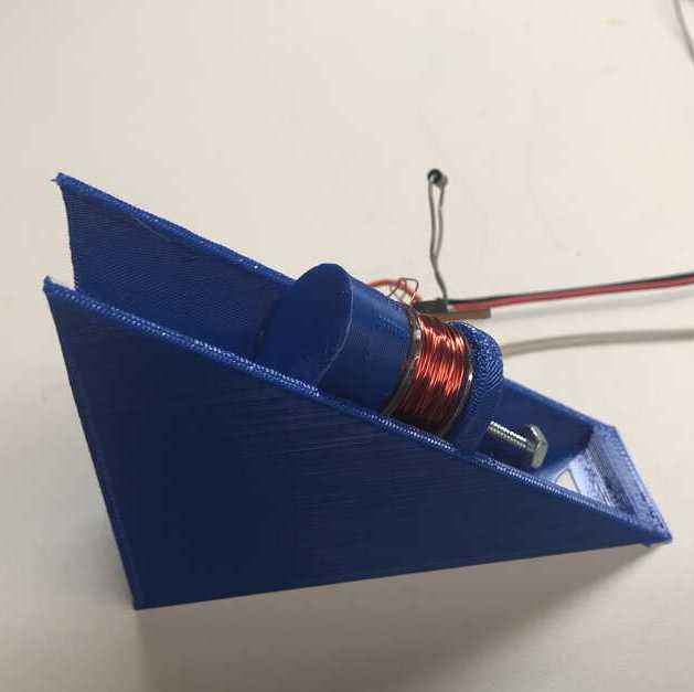
After I went to the lab and measured the solenoid, I updated my parameters and printed my holder on the Prusa 3D printer.
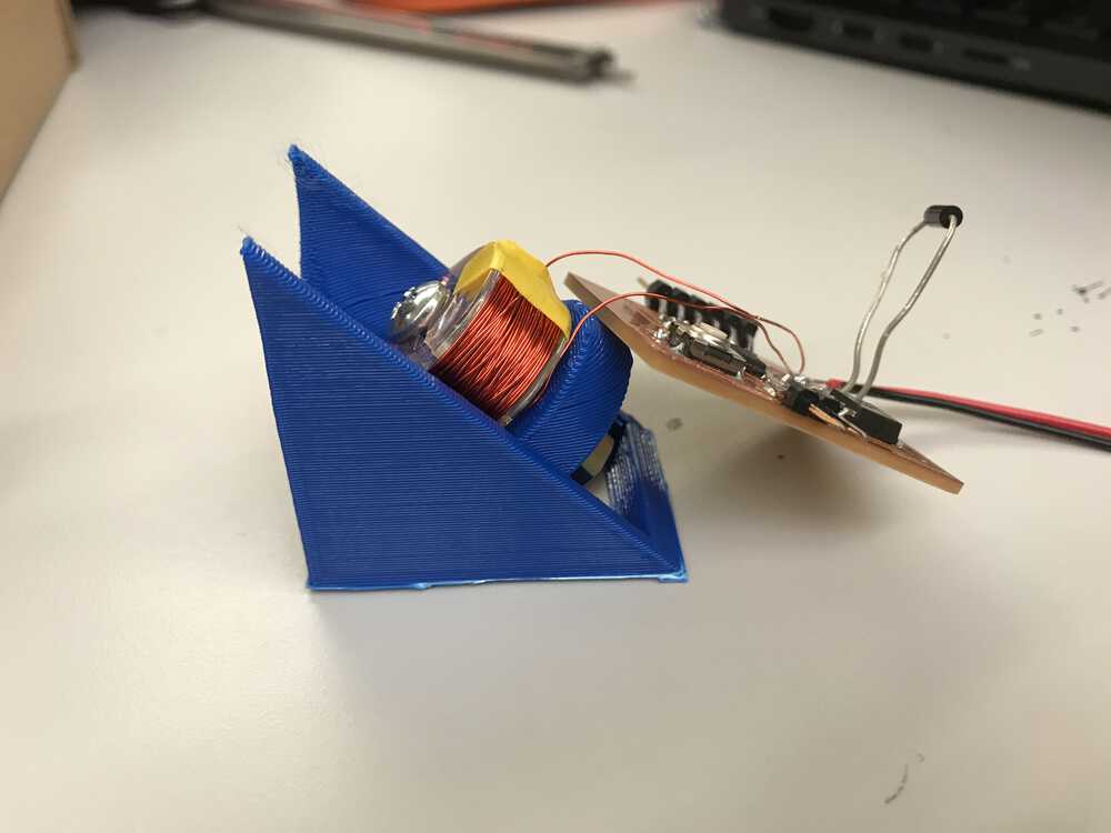
Solenoid in 3D printed solenoid holder
Solenoid launching a treat
I noticed that the launcher was a little too small to hold the treat, so I went back to the drawing board and redesigned the launching holder to allow for more room for the treat. I also found a much more magnetic (but longer) screw which would allow for more velocity. Therefore I had to adjust some of the parameters. But since I parametrically designed this solenoid holder, it was quite easy.
Updated solenoid holder
dropping mechanism
Like I explained in prior entries, I was going to implement a treat dropping mechanism that is similar to the ones in gumball machines. I would have 3 separate parts: a loading tube, a spinning disk with slots for 3 treats, and another tube to send a treat from the disk to the solenoid. Knowing that my treats will be small discs with around a 0.75” diameter, I could CAD my dropping mechanism.
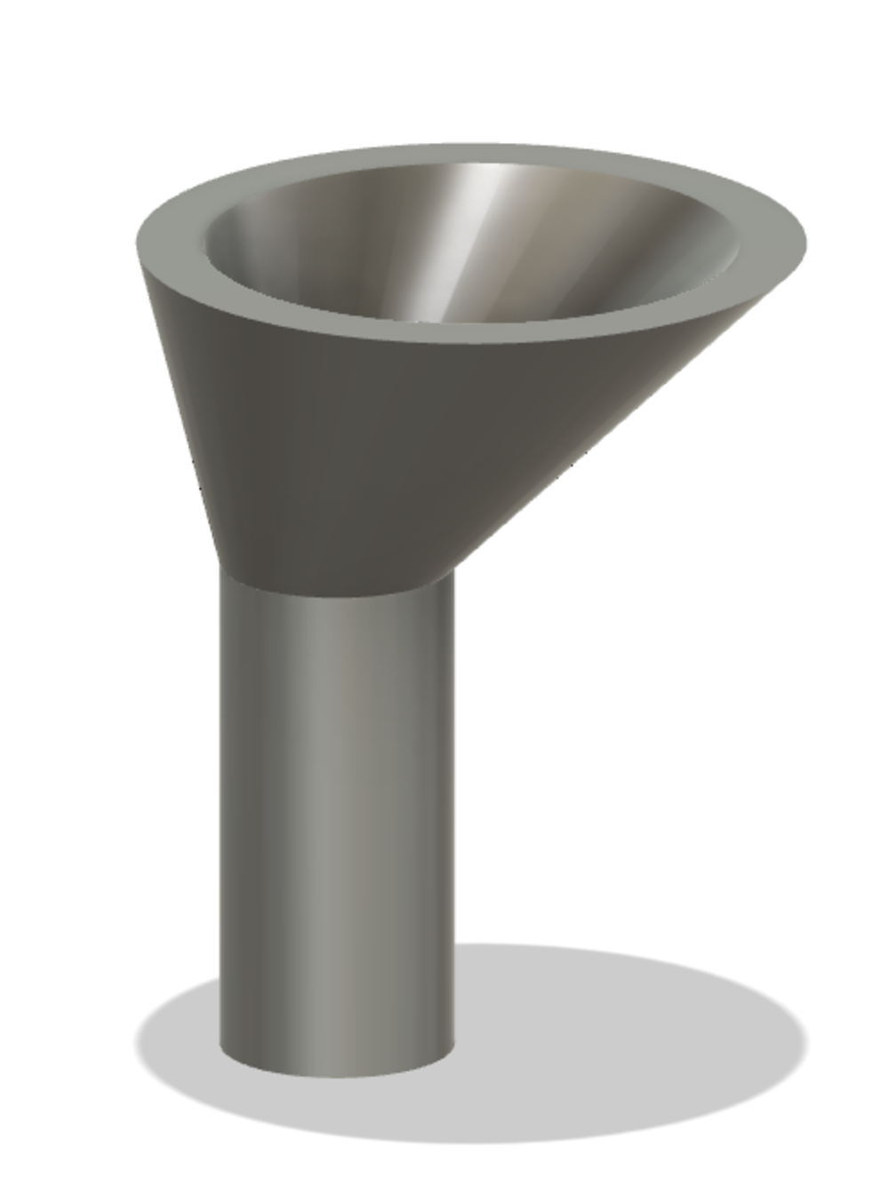
I started CADing the loading tube: this is where all the treats would be stored in batches. I envisioned that I could store a handful of treats in the top half that would be shaped like a funnel. This funnel would fit perfectly into my housing. There would be a tube attached to it that would hold the queue of treats waiting to be inserted into a slot in the loading disc. This design allows me to store many treats and create a structured path for the awaiting treats.
I started CADing the loading tube: this is where all the treats would be stored in batches. I envisioned that I could store a handful of treats in the top half that would be shaped like a funnel. This funnel would fit perfectly into my housing. There would be a tube attached to it that would hold the queue of treats waiting to be inserted into a slot in the loading disc. This design allows me to store many treats and create a structured path for the awaiting treats.
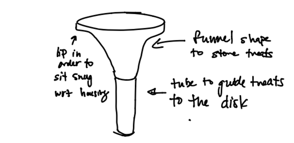
Sketch of my dropping mechanism
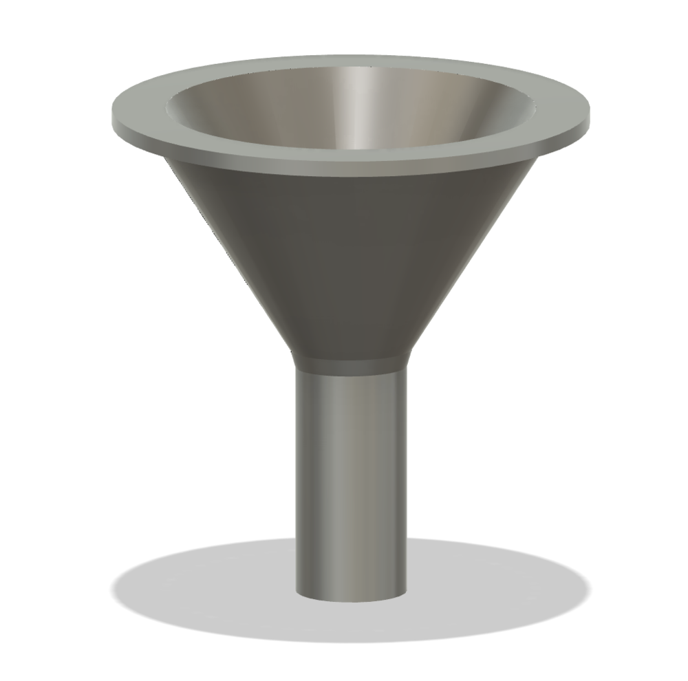
CAD of funnel
However, I knew I didn’t want my loading tube to lie in the middle of the disk, but rather offset to one of the sides where the indents would be. Therefore I updated my design to include a funnel that had its opening offset to the side.
CAD of offset funnel
For the tube diameter, I gave myself some wiggle room based on the variable size of treats by making it 22 mm or .86” wide. I also parameterized the height so I could make it larger or smaller based on the desired size of my housing. I then 3D printed the loading funnel on the Prusa and it turned out nice.
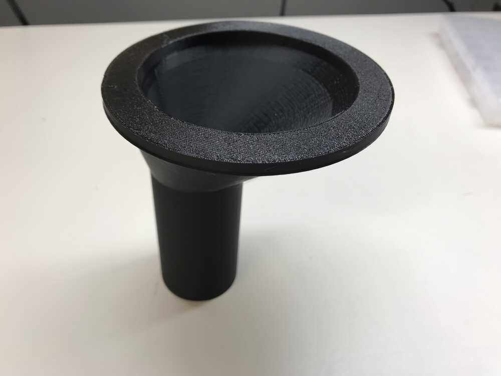
3D prined funnel
The tube to send the treat from the disk to the solenoid was pretty straightforward. I copied the design and parameters of my tube from the loading tube and just varied the height parameter.
Lastly, I had to design the disk. There will be two main parts of the disk: the disk with the 3 inserts and a base that would prevent treats from falling out of the inserts until it reaches the tube. I plan on using a gear on the stepper motor to rotate the disk, so I will need to make teeth on the shaft diameter that fits with the teeth of the gear I will be using or by press-fitting my disk to the shaft. Additionally, I will use a bearing for the disk so that as the shaft moves, the base will stay in place.
I decided to have the tube that would send the treat to the solenoid to be flush against the housing. Since the disk is rotating I couldn’t add a tube to every insert. I plan on adding a tube in the internal housing since the launch location will be in the same location every time. If treats got stuck, I would be able to unclog the tube pretty easily so this design should be fine.
CAD of loading disk
Once I had a rough CAD design, I planned on printing out a prototype. I was in between laser cutting acrylic and 3d printing, so I planned to try both. Since I decided on press-fitting my pieces with the shaft, I experimented with different hole sizes to see what fit my stepper motor shaft. With the acrylic, I found that a diameter of 4.8mm fits very nicely. For the 3D printed hole, none of the 4.8mm, 4.9mm, or .50 mm fit. Since the 3D printed way took much more time, I planned to use acrylic.
Experimenting with tolerance of acrylic
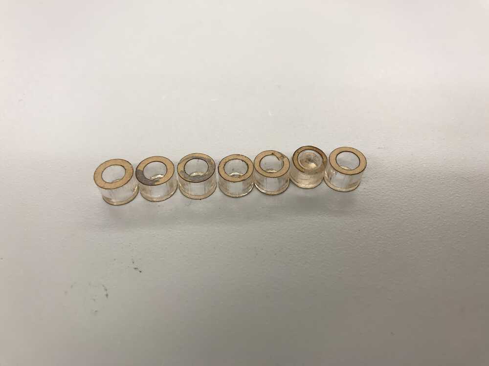
I also needed to cut out acrylic pieces to put in between the bearing I was using and the shaft since the bearing diameter was too large. On top of this, I needed to cut out another acrylic piece that would see what size hole fit around the bearing. I set out and cut 8 different sizes ranging from 8.5 mm to 9 mm to see what would fit inside the bearing and discovered 8.5 mm was the best. Next, I cut out 4 different sizes for the other acrylic hole that would go around the bearing and found 21.9mm fit great. With these two tasks done I could put both the base and disk on the stepper motor and tried to manually control the disk to emulate what would happen in real life.
How the disk will drop one treat at a time
I did run into an issue as I prototyped my design on a unipolar stepper motor which had a longer shaft than the bipolar stepper motor which I was planning on using. I am planning on using the bipolar motor since it has 2 fewer pins that are needed, which is important since the ESP32CAM doesn’t have too many pins to use. To handle the smaller shaft, I planned on not using a bearing for the base piece and just cutting a circle that would hold the base flush against the motor. I would also use thinner material for this base since all it needs to do is support the treats. If I implemented these changes with the base, my disk could keep the same specs.
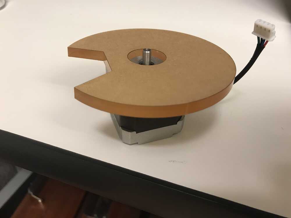
Flush base on stepper motor
I also noticed that my inserts in the disk were too large as I could fit two treats easily in one insert. To solve this problem, I went back to Fusion360 and decreased the area of the insert by a significant amount. Before, my design fit a 25mmx25mm square inside each insert, but this was way too large for my treat size, so I made the insert fit a 20mmx20mm square. This worked much better than before. Additionally, I only had one insert, as my stepper motor would simply do one rotation to drop one treat to the solenoid, so I removed the other two inserts that were evenly spaced.
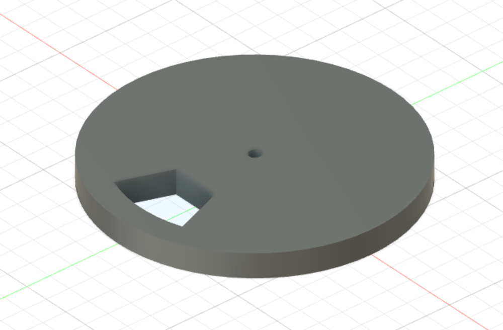
Lastly, I decided that since my base disk was going to stay in place, it would be a good idea to directly attach the tube that would send the treat to the solenoid holder to the disk base. This would allow me to ensure that the tube and insert would align perfectly. I wanted to also decrease the height of the tube since more height could cause the falling treat to bounce around more in the solenoid holder.
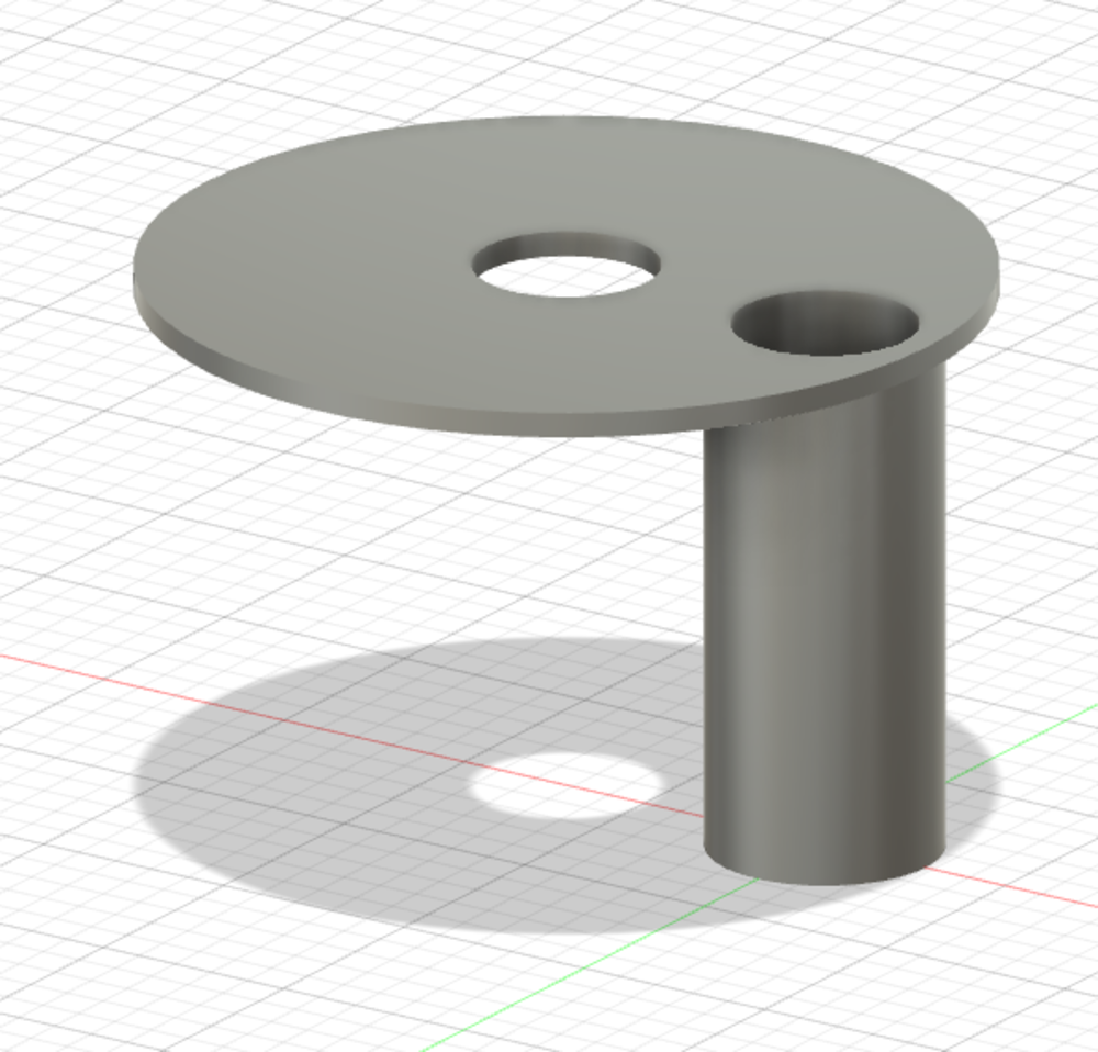
CAD of new base with tube attached
Since I had the tube attached to the disk base, I could no longer laser cut this piece so I decided to 3d print it. I had to again experiment with diameters for the internal circle that would fit snuggly with the indent in the stepper motor.
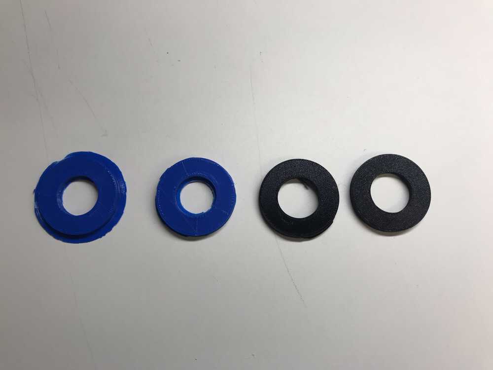
Test 3D printed pieces to find dimension that would fit snuggly
After finding the right size of 22.1 mm, I next had to figure out what a good height would be for my tube. After measuring how large the stepper motor was (40.5 mm), I knew my tube had to be at least this tall. I added an additional 20 mm to the height of the tube so that there would be sufficient room for my treat to drop into the solenoid holder. I then printed out my new base.
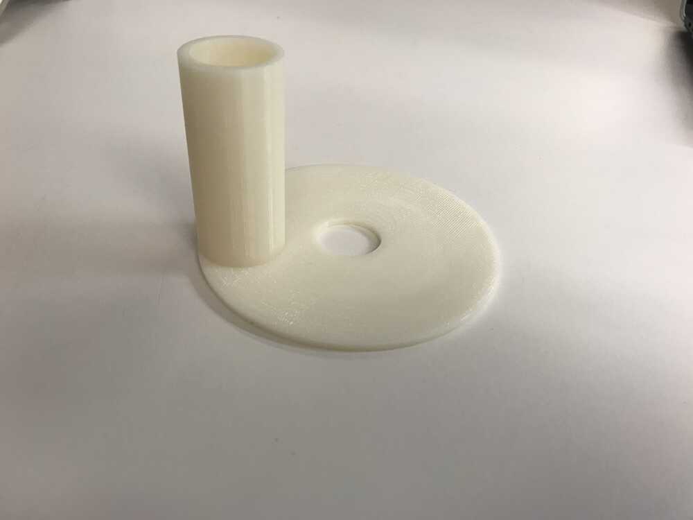
New base 3D printed
New base and disk in action
NEXT>