final project: programming
November 19, 2020
One of the last things I wanted to complete before we lost campus access was to be able to successfully control each of the components that I was using for my final project (camera, stepper, speaker, and solenoid). I envisioned that virtual debugging at home with Anthony over zoom would be very hard, so I tried to take advantage of the rest of lab time.
camera
One of the main reasons I chose to use the ESP32CAM was because of the camera feature. After hooking up the ESP32CAM to my board, I was able to see a bright LED from the board. I then went to File > Examples > ESP32 > Camera > CameraWebServer and grabbed the sample code that would display the camera feed on a localhost webserver. I ran into many issues when I tried to upload the code.
The first solution to my problem was I was running 5V from my serial connector to the 3.3V pin on the ESP32CAM. Once I fixed this with the jumper cable on the USB connector, I got a brownout error. This is because my connector was only transmitting 3.1 V, while the ESP32CAM was expecting 3.3V. To counteract this I could have attached a 3.3 voltage regulator from the VCC of the USB connector and passed in 5V from the USB connector. However, I didn’t want to cut another board. Luckily, my barrel jack was accepting 9V from the outlet and passed through a 3.3V regulator into the 3.3V pin. So I used the power from the wall charger as opposed to the USB connector and it worked!
One important note is that the slide switch needs to be switched into either programming or run mode depending on what I was trying to do. Additionally, after I flipped the switch, I would need to press a button underneath the ESP32CAM to change modes.
I was able to run the camera code and display on a local webserver the camera feed!
Livestreaming video on the ESP32CAM
stepper
As noted in previous weeks, I had many problems with the stepper motor working. However, Anthony figured out a solution and advised me to add a couple of resistors in series leading into the VREF of the H-bridge. This would allow me to control the current I was passing into the stepper motor. We experimented with this on a breadboard and found that a resistor of 5.1 ohms and 2.7 ohms worked. Therefore, I soldered my board and looked for the right pins to activate in my code. I then used the Stepper.h library to run the motor and uploaded the code to the ESP32CAM. Luckily my stepper motor worked!
Stepper motor dropping treat
One odd functionality I saw was that my 200 step stepper motor didn’t make a full rotation when I set the number of steps per rotation to 200 in my code. This was interesting and Anthony suspected it could be that the H-bridges were overheating so it didn’t move all of the steps. Additionally, there was a loud hissing coming from the stepper motor and the H-bridges got really hot. To counter this, I experimented with larger resistors to decrease the current to prevent this from happening. I found that a 3K resistor worked really well and I was able to get one clean rotation.
solenoid
Luckily, last week I was able to experiment with the solenoid and how to get the solenoid working. This experience made the integration of the solenoid relatively easy. With my solenoid traces cut/connected correctly, I set off to program my solenoid to activate. I did so by simply setting pin 4 (the pin that was connected to the gate of the MOSFET) to be high to activate the solenoid. This worked on the first try after I soldered the wires from the solenoid.
speaker
The last piece of my board was the speaker. I had trouble getting the speaker to output loud noises when experimenting with the breadboard so I was not expecting much. Anthony and I looked for some Piezzo speakers because he thought they would be louder, however we had no luck. This was unfortunate, however I was forced to stick with what I had. This was fine because the speaker was an extension to my final project.
I first tried using the tone function from Brett Hagman’s library, however it didn’t seem compatible with the ESP32CAM. Therefore I did some googling and I found others that had run into this problem. To solve this, they just implemented their own tone function using pwm. This worked and I was able to get a faint noise, but I will experiment more with this later.
I first tried using the tone function from Brett Hagman’s library, however it didn’t seem compatible with the ESP32CAM. Therefore I did some googling and I found others that had run into this problem. To solve this, they just implemented their own tone function using pwm. This worked and I was able to get a faint noise, but I will experiment more with this later.
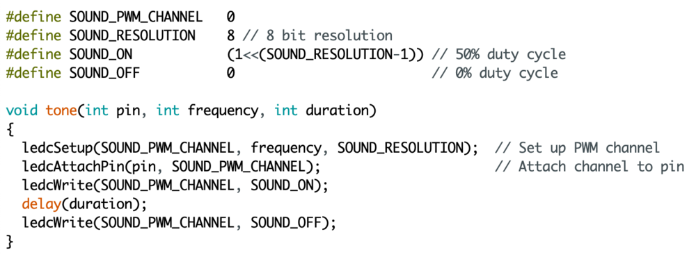
Self-implemented tone function
final product
I was able to integrate all of these components and activate all of them at the same time like they would in my final device. For my final device, I would press a button on my phone via bluetooth and this would activate the dropping mechanism, then the speaker, and finally launch the treat via the solenoid.
I mocked these steps by writing code that would do this in the same order.
I mocked these steps by writing code that would do this in the same order.
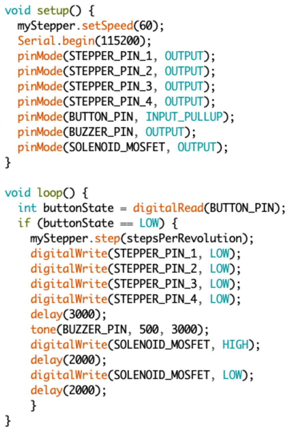
Code to handle three components with one button press
All components activating in order on a button press
With all of the components working, I can customize the time in between each action for my final device. I still have to put the entire housing together and try to see if these components work in there, but I think I have made great progress over the past couple of weeks.
NEXT>