Week 10
This week was spent around output devices.
Stepper output
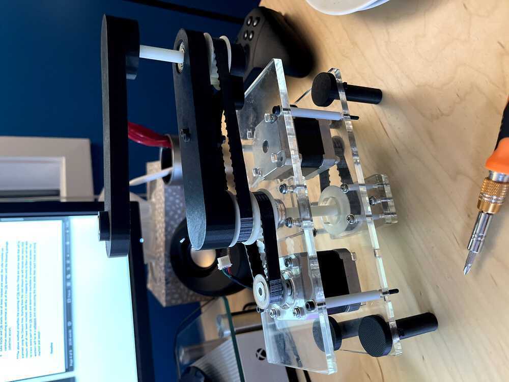
My output device chosen was a stepper motor. Well 2 stepper motors. This is a part from my final that was used to power the final board and rotations. See the final document for details on how it plays into my other parts together.
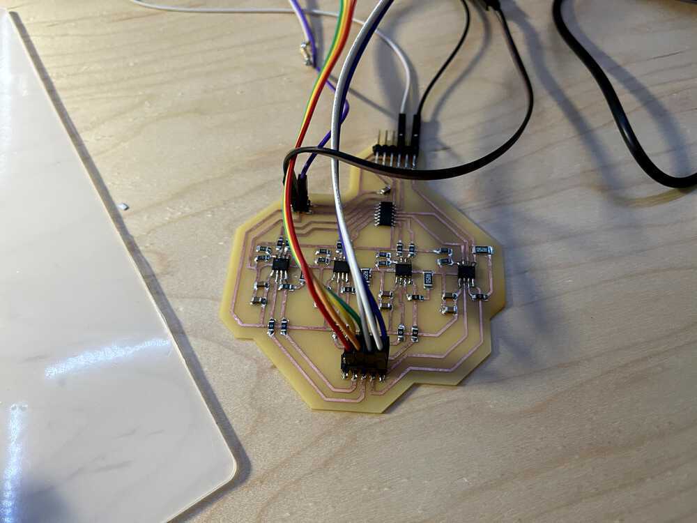
I finished off the project using the same board as mentioned in the project page. The board has 4 h bridges, an attiny1614 and many resistors and capactiors. Each H bridge is powered by a central line of wall power coming in at 9 volts with a barrel plug converter from the wall. This is used to get gnd and wall power to the system. In addition, each h bridge is connected with 2 capactiors to reduce the variance in voltage going through the h bridge system. Each h bridge takes in 2 outputs from the 1614, gnd, vdd, and vbb. This is then converted into 2 outputs each that are fed into an 8 pin connecter at the end. These 8 pins are the wires going into the 2 steppers (4 per stepper).
The stepper motors are coded with c code and then controlled by an ATTiny1614. The two motors are able to spin with commands that are given to the motor from the microcontroller. The code is below.
I learned a lot about how to program a stepper this week! It took way too much effort to get the stepper running correctly but was super exciting when they both spun!
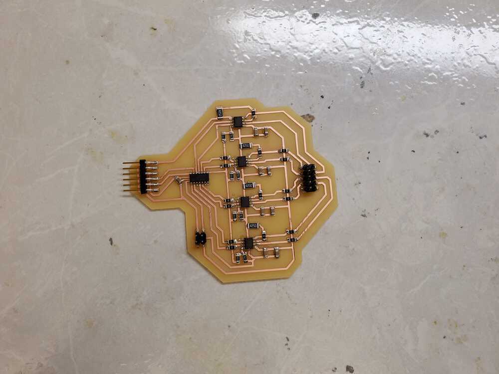
board
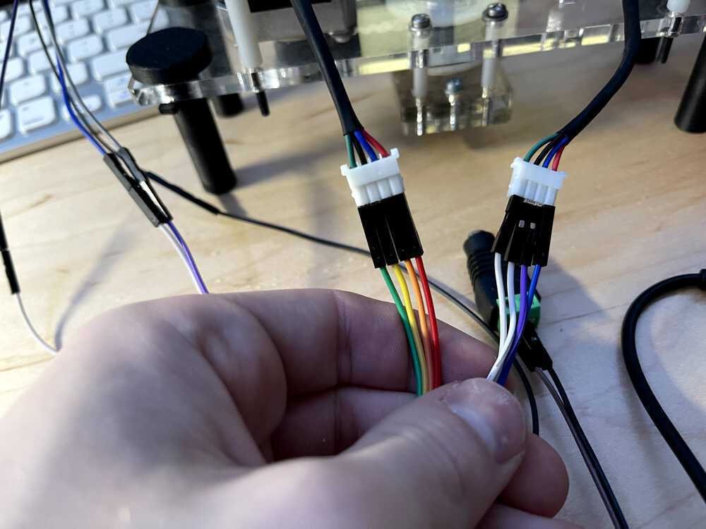
the wires into the output
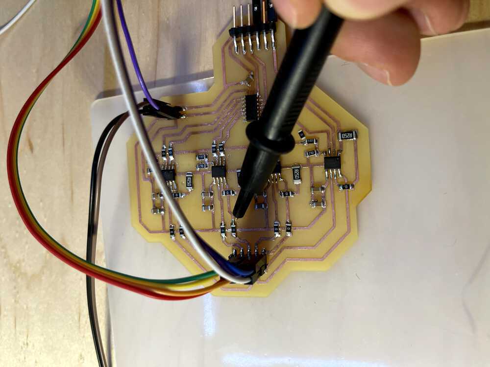
Probing for issues
Debugging
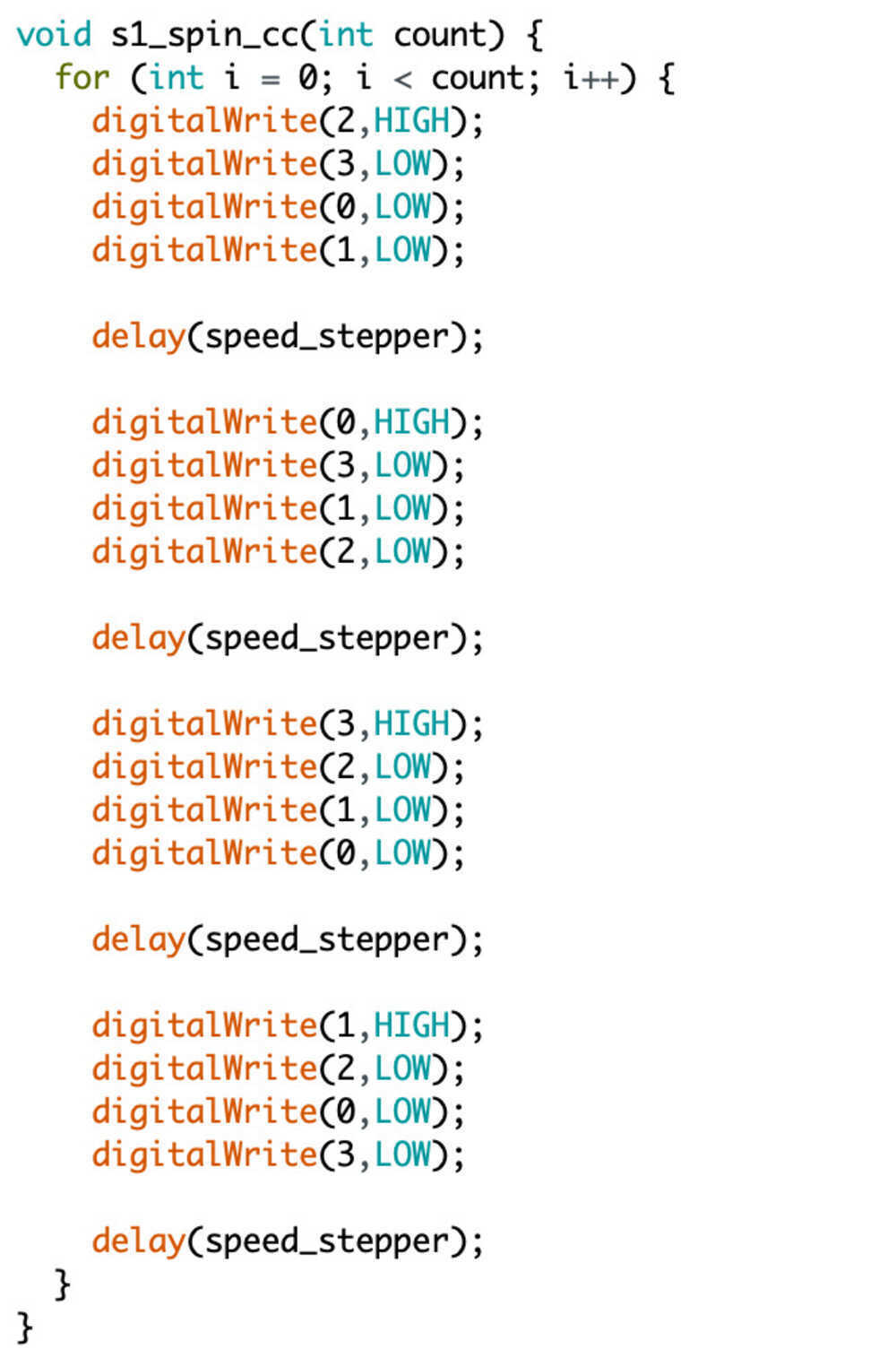
code for s1
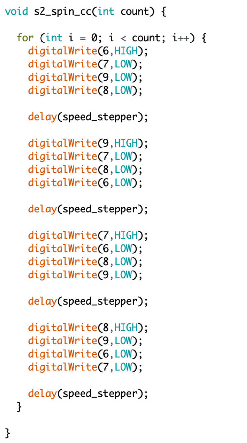
code for s2
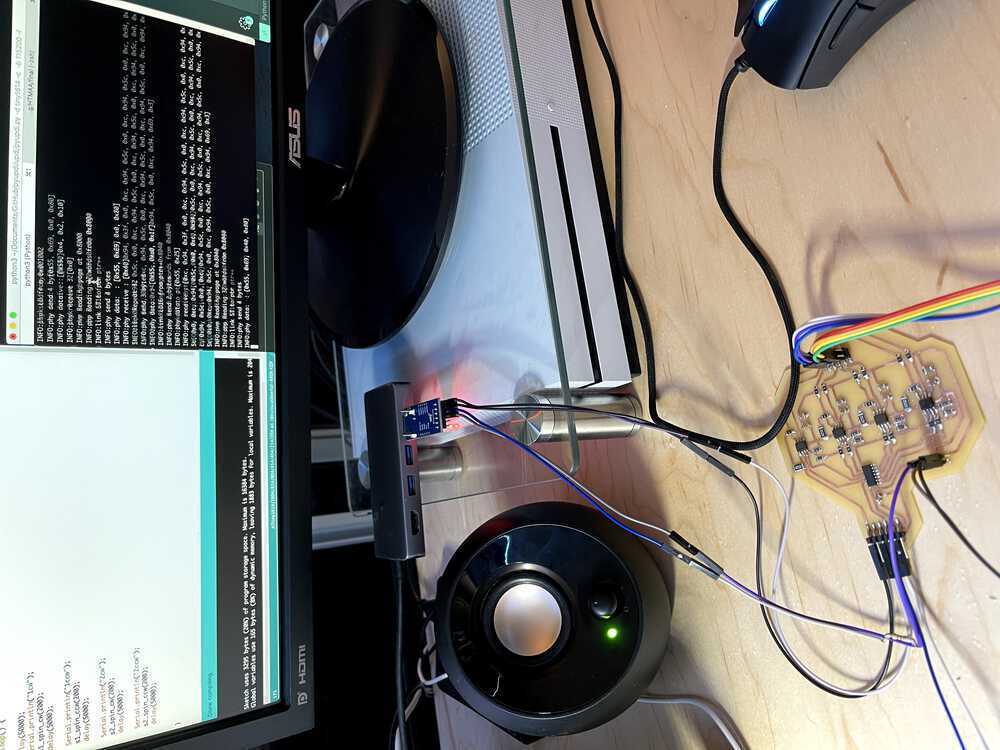
coding steppers