Week 11
This week was spent on software applications
Applications
I used this week to create the software for my final project. It is a gui that encompases the vizualization for my machine that I am building.
Software
For the software I wanted some way to control the steppers to make the shapes I wanted. In addition, I wanted a way to be able to have inputs go back into the laptop and be displayed as they were happening. Ideally this would be built into an app on a phone but we work with limited time here.
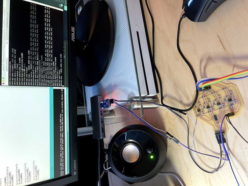
For the stepper code, I used the Arduino ATTiny1614 megacore library to program my microcontroller. I was able to write code, upload through updi and then run the code while being plugged in with wall power and the laptop programmer. This amounted to a slower development cycle than I had hoped (with switching wires back and forth between programming and testing) but was successful anyway. For the stepper file, I created multiple functions that would do the turning for me. For the first stepper, the correct pin ordering was 2-0-3-1. I originally had these spin with 0.002 seconds between each pulse; however, this was too fast so I switched this to be 0.004 seconds between each. I created functions to spin arm 1 for a certain amount of degrees clockwise, arm 1 counter clockwise, arm 2 clockwise, arm 2 counter clockwise, and then combinations to have them move at the same time in either cw or ccw directions. I also created some functions for microstepper the top arm to make a more smooth motion for the stepper and be able to handle 0.008 second waits between different pulses...it did not like this 100% of the time but was the current best solution for handling the slower movement from the steppers while remaining smooth. The way to flash the microcontroller is with: python3 ~/Documents/GitHub/pyupdi/updi/pyupdi.py -d tiny1614 -c /dev/cu.usbserial-AR0K4ZJX -b 115200 -f ~/Dropbox\ \(MIT\)/School/Meng/HTMAA/final/stepper_oneRevolution/stepper_oneRevolution.ino.t1614.20c0.u5V.mD0.hex -v
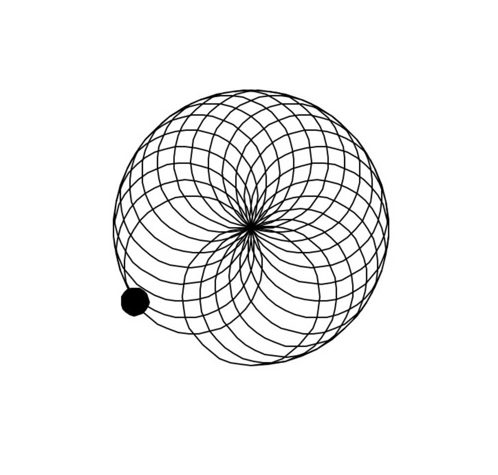
Now I moved onto the software for the vizualization side. I was able to (with a lot of Anthony's help) get the c code running on the microcontroller to post when it was doing certain movements from the functions mentioned above. It would cast this over serial and a python script of mine would be looking for said input. It could read this input and start to display it using a library called Turtle (https://docs.python.org/3/library/turtle.html). This tool was easy to pick up and did the basic display needed for this project. On a command start from the hardware, the software would also start to vizualize the same trace that is being made by the ball at the top of the arms. This started to come together really well in in the synchronization since I created the ball moving on the screen to match the speed of the arm movements. This should be ported to an app fairly easily at some point. I created functions for the machine to be able to do a looping circle. It creates a circle with the top arm and afterward moves the arm holding it by 5 degrees and repeats. This creates a lily pad-like pattern on the design. In addition, I created a spiral that spirals from the center out. This can be reversed and have the spiral work on the way in.
The code is attached
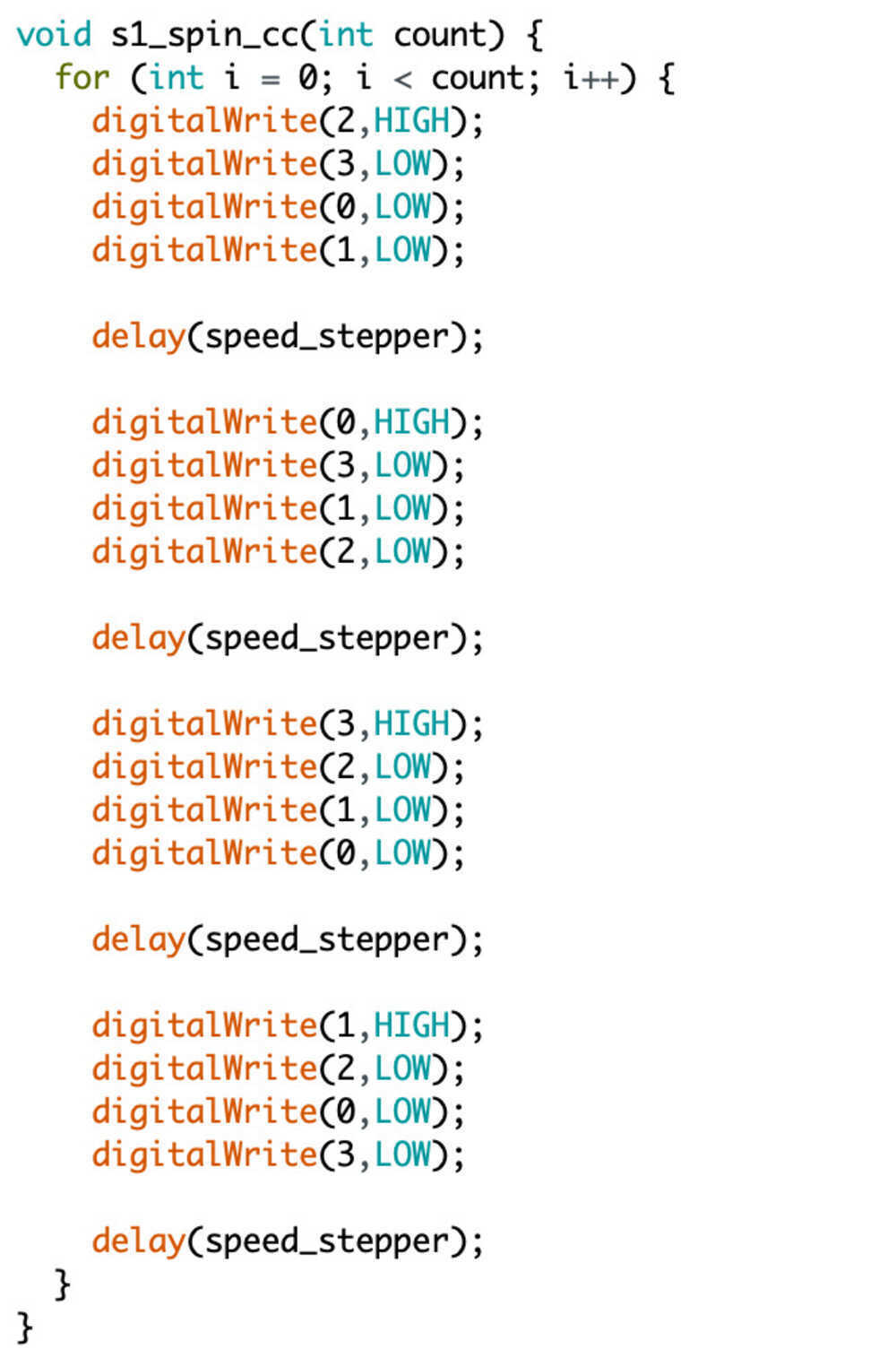
code for s1
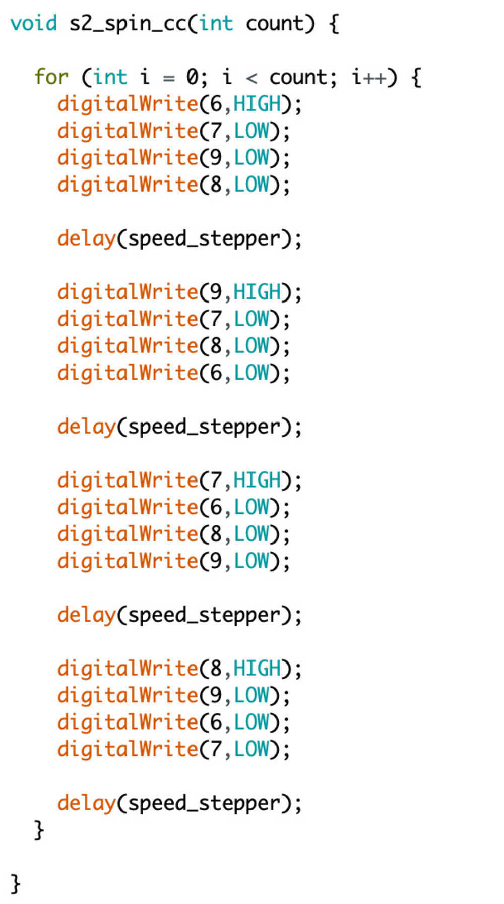
code for s2
coding steppers
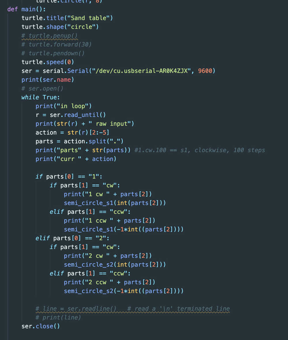
python code