Week 9
This week was spent around input devices. This is a continuation of week 8.
Reading a datasheet
This was my first time reading a datasheet. I wanted to create something cool that would be helpful to me in my final project. I decided I wanted to combine week8 and week9 together in this while using the skills I had learned from the previous 2 weeks to incorporate that into the design overall.
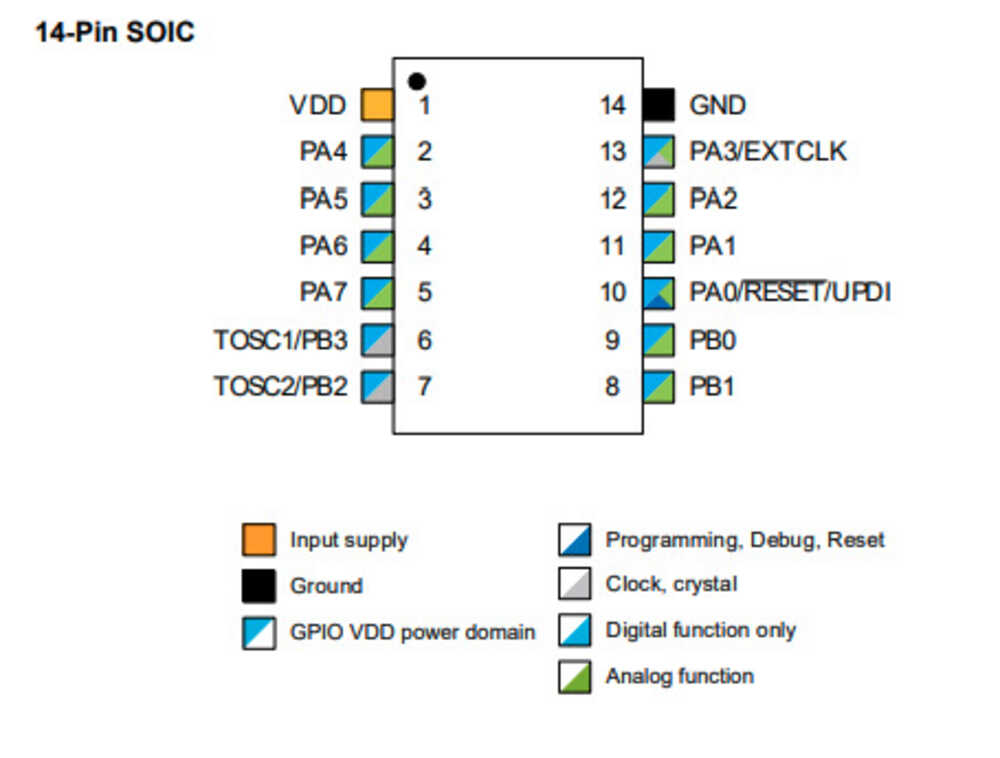
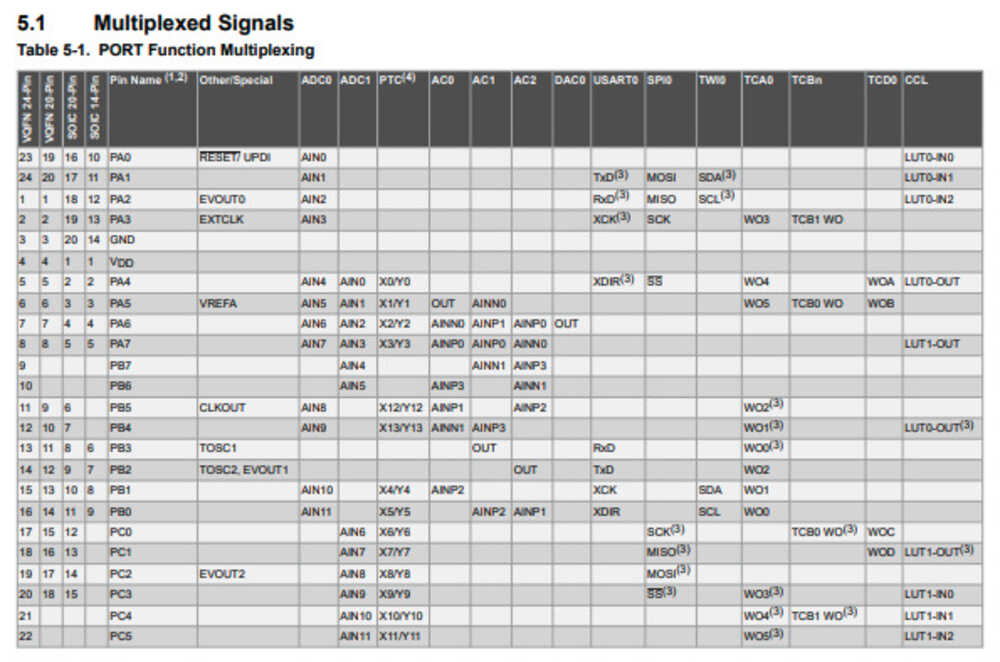
I picked a new chip, the Attiny1614 to use since that is what we have in the kits and in the stock room. I pulled up the spec sheet for the chip and started to analyze how this worked from the different pins. I needed a lot of help from Anthony in deciding what to do with each pin and what each pin would do. I learned a lot about analog vs digital inputs into a pin and the recieving vs sending of a chip. The 1614 documentation is really well made and it is easy to work with in the 2 pin to incorporate it into the board.
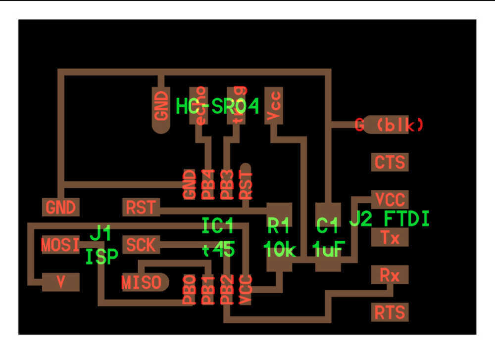
The schematic for the 1614 board
Figuring out the TxD and Rxd for the 1614
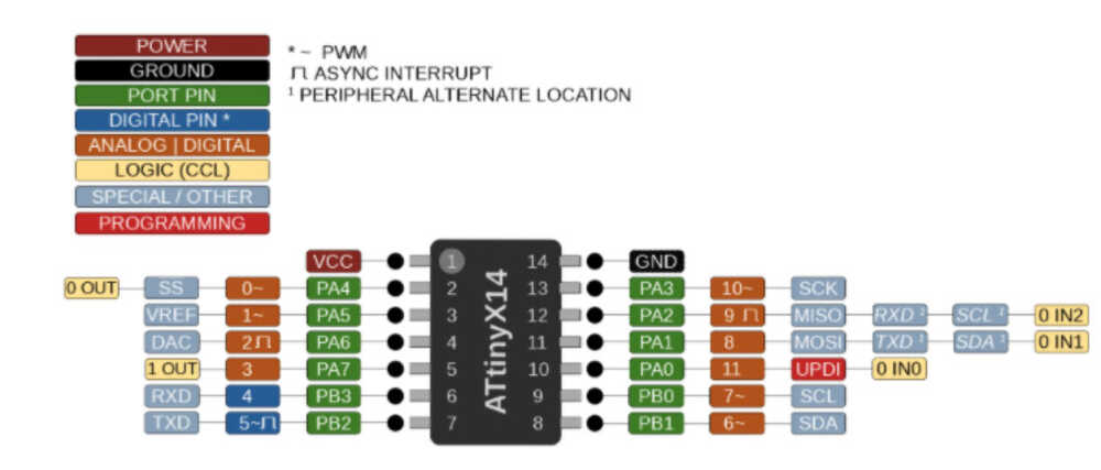
The input output to detect which pins are good for analog (it is the ~ on 7 and 6)
Making a board
I decided I wanted to make a new board for this week. While it was cool what I did last week with the LED I wanted to do something different for this week with input sensors too. I looked at the different types of inputs and decided to go with the sonar input. This can detect how far a device is from the sensor.
The board I based mine off of
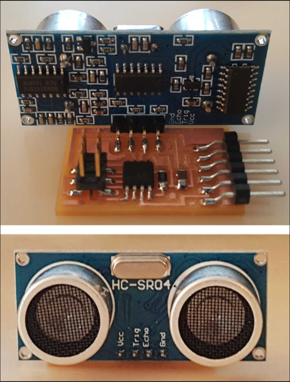
The assembled board I used to start off with
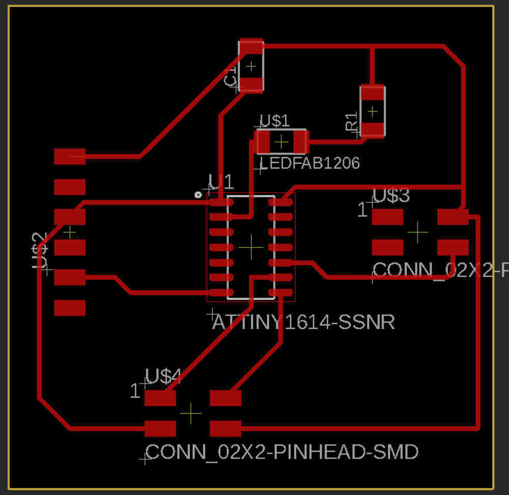
The board I created for this week with the sonar
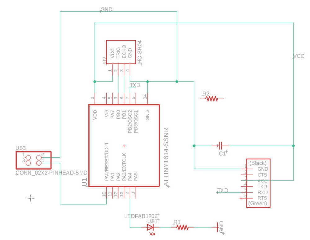
The schematic for the week with the sonar
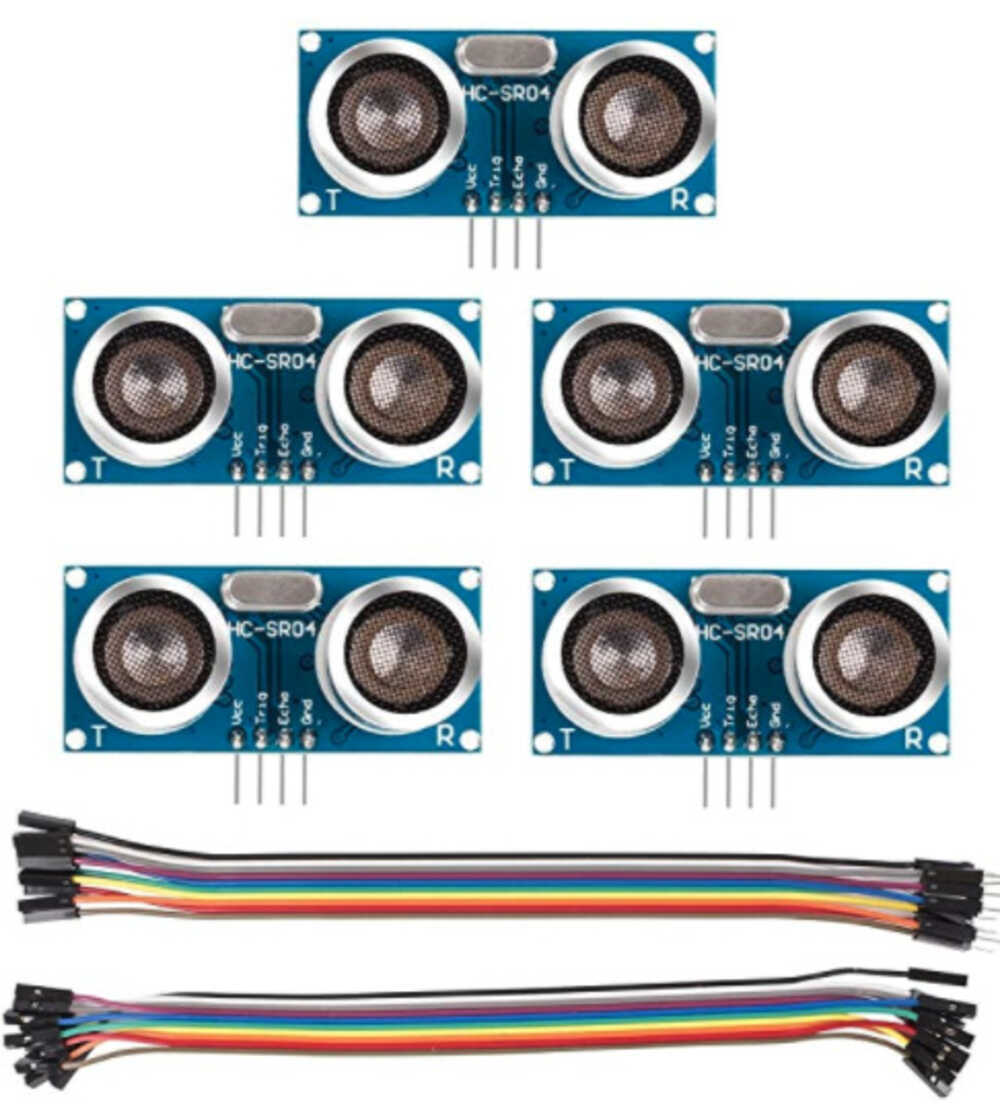
The sonar sensors I will put on the board
I created a new schematic in Eagle and used a lot of my learnings from last week to guide my approach in doing this. I started with a similar hello world board to what was refrenced online but used a different chip. I switched from the Attiny412 to the Attiny1614. This was a different chipset than I had used lastweek so I started looking at the documentation for the new microcontroller.
My goal was to create a board that would light up a light if something was within a certain distance away from the sonar input device. I created an LED with a resister to ground and the sonar sensor linked to that.
Cutting the board
I cut the board out and it looks really good. I used the 1/64th and the 1/32nd bit to do so.
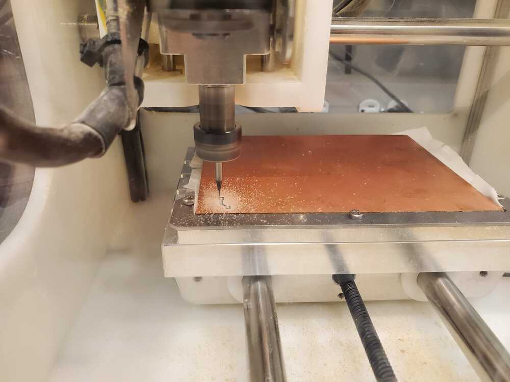
The Othermill cutting the board out
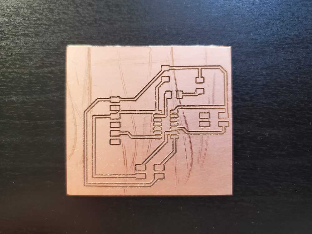
The final cut out before soldering
Programming the Board
I installed the Arduino IDE to program on the board. Installing the correct core modules for the ATTiny chips was difficult but I figred out how to do it. I started to write out my program to blink a light based on the distance the sonar sensor detects from the board and light up the light based on it.
Input devices on final
I used the input device of the microcontroller on my final project to trigger a software program I created on my laptop. The microcontroller was a 1614. The microcontroller talked back to the program Arduino code. In my Arduino code, I am spinning 2 stepper motors that are powered with my custom pcb. The program has 8 pins output to the 2 steppers (4 each pins each). These outputs are used to power the stepper for the correct amount of turns that are sent to it.
I created a listening program written in Python that listens to the port that was opened with the microcontroller when it starts to operate. The Python script then supplies a vizualization to the user. The script is a Turtle script that helps the user see what the device is doing at a point.
Mor specifically, the command would be cast over serial and a python script of mine would be looking for said input. It could read this input and start to display it using a library called Turtle (https://docs.python.org/3/library/turtle.html). This tool was easy to pick up and did the basic display needed for this project. On a command start from the hardware, the software would also start to vizualize the same trace that is being made by the ball at the top of the arms. This started to come together really well in in the synchronization since I created the ball moving on the screen to match the speed of the arm movements.
For some images of this, see the projects page