So anyway, I plug in the solenoid, I connect the power input 2x02pin to the benchtop power source and oops, the solenoid fires yet I haven't given the D11C a command to do so...
In the video you can hear the click of the solenoid piston firing and you can also see my orage kickback LED successfully dissipating the negative current being formed when power is taken away from the circuit. But what you cannot see is the solenoid firing every 3 seconds like I instructed it to do so in the code.
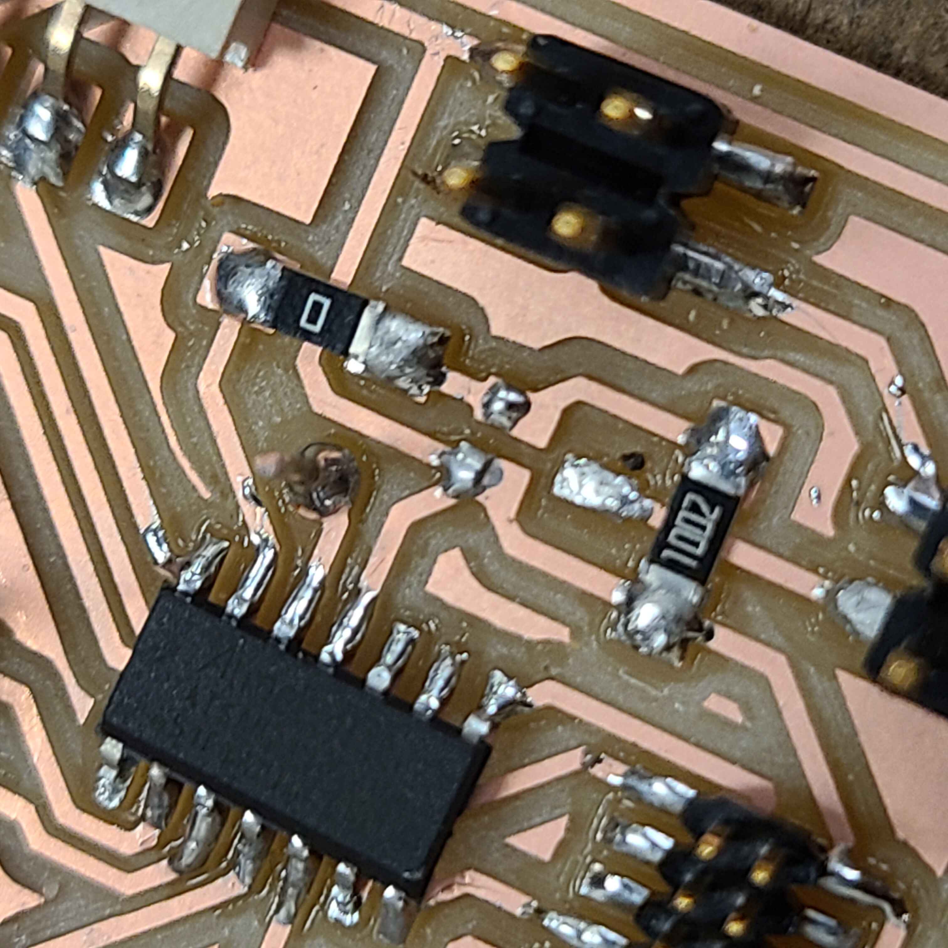
I consulted Anthony, who suggested taking a multimeter reading of the MOSFET Gate pin when the PCB is plugged into power. This is to determine whether the D11C pin is functioning correctly. I haven't got a picture of the multimeter but you can trust me when I say that the voltage reading was circling between 0V and 0.388V every 3 seconds. This 3 second interval is correct and it corresponds to my initial code, but the 0.388V is wacky. Anthony mentioned that the MOSFET may have a short or has simply suffered a catastrophic current spike and is not performing its job correctly. He instructed to take the MOSFET off, inspect it and its traces for shorts and retake the multimeter test.

With the MOSFET taken off and no shorts in sight I consult the multimeter. It now reads 0V to 3.3V every 3 seconds! Why you may ask, and to be totally frank, I have no idea. I guess te MOSFET must have suffered some damage. If I solder on a new MOSFET everything should be working just fine.

Time to test the circuit...
It works!!! With a press of a button I send 3.3V to the MOSFET gate, passing its gate threshold voltage, which closes the circuit taking current from my external power source through my 12V load and down to gnd. As an additional bonus a green LED lights up when the button is pressed. Below is the code for this week.
	const int ledPin = 15; //pin 5 - PA15 on SAMD11C
	const int buttonPin = 14; //pin 4 - PA14
	const int fetPin = 2; //pin 13 - PA02

	int buttonState = 0; //variable for reading button

	void setup() {
	  // put your setup code here, to run once:
	  pinMode(ledPin, OUTPUT);
	  pinMode(buttonPin, INPUT);
	  pinMode(fetPin, OUTPUT);

	}

	void loop() {
	  // put your main code here, to run repeatedly:
	  buttonState = digitalRead(buttonPin);

	  if(buttonState == HIGH){
	    digitalWrite(ledPin, LOW);
	    digitalWrite(fetPin, LOW);
	  }
	  else{
	    digitalWrite(ledPin, HIGH);
	    digitalWrite(fetPin, HIGH);
	  }
	  delay(250);
	}