The Lunar Exploration Roadmap Objective FF-A-7 calls on us to “provide or construct structures on planetary surfaces adequate for long-duration habitation by humans and made of materials that will endure extended exposure to the deep space environment.” In line with this objective, my project would tackle three key topics:
1. Designing, manufacturing, deploying and testing lightweight expandable structures in Lunar gravity.
2. Exploring the benefits to astronaut comfort and mental health on long-duration missions thanks to the high-volume and welcoming, human-oriented interiors allowed for by such designs.
3. Testing of architectural and structural synergies that low-pressure, low-gravity environments provide in conjunction with new material developments.
When we return to the Moon to stay we will not immediately have the backup of sophisticated infrastructure to assist us in setting up a base. We will still rely on structures we bring from Earth. It is vital, therefore, that we aim to maximize interior volume whilst minimizing weight and cargo space for such structures. Expandable architectures are one such opportunity. They not only satisfy the ratio of volume to weight/cargo, but also capitalize on the large pressure difference between the interior habitat and exterior vacuum. Since all habitats on the moon will have to overcome this pressure difference they will all have to work predominantly in tension. This is an ideal set of constraints for expandable architecture. Additionally, the lower lift cost of such structures will mean a more accessible space to budding space-faring nations or companies.
As our extra-terrestrial presence grows and our missions become longer we must take astronaut comfort and mental health even more seriously. Those living on the Moon will not share the same ISS peace of mind of being “within reach” of home. Architects must develop structures that nourish the mind and instill a sense of comfort and safety. Expandable habitats could do just that. Their large, soft interior volumes would provide more room for social spaces, larger living quarters and could even conform to the new realities of human mobility in low lunar gravity. Following the flight, the project could delve into research about human-oriented design that could supplement architectural findings from microgravity.
Lastly, the unique structural affordance of low gravity, the efficiency of tension over compression and the challenges of a hostile lunar environment provide an excellent opportunity to test material and construction method synergies. I plan to take advantage of my building technology experience, my classes on structural optimization and other resources within the building technology department at Course 4 (Architecture) to gain insight into promising materials and devise experiments and simulations that will single out structurally efficient materials that can resist stressors within the lunar environment.
Experimenting with Kangaroo
I wanted to start off by doing some form-finding exercises in Grasshopper’s Kangaroo 2 plug-in. I thought I might need to familiarise myself with the way its components function so that I’d have an easier time iterating through the designs of my inflatable lunar structure in the future. Kangaroo is very good at simulating forces in rigid and flexible bodies, but doesn’t produce a numerical precision that might be necessary for their ultimate fabrication. I suspect that any work I produce in Kangaroo would have to be independently tested in real life, but at least it gives me a good point of reference for what a desirable membrane or tension element could look like. Anyhow, here are the three experiments:
As you can tell I’m no master of Kangaroo. The plug-in has a lot of opaque controls and it takes time to figure out what other components you require to make everything work well together. From the three attempt above, I figured that Kangaroo needs the forces to be applied to the same object if you wish to have them interact with each other. If these forces are applied to different objects, they simply don’t want to collide and influence each others’ motions. I’ll need to play around with it some more to get better control. In the meantime I will switch to some physical experimentation next to get a better grasp at silicone casting.
Casting Silicone Membranes
This week I wanted to dive into 3D printing and casting silicone moulds akin to the process of making soft robotics.
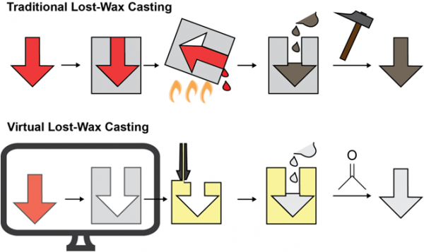
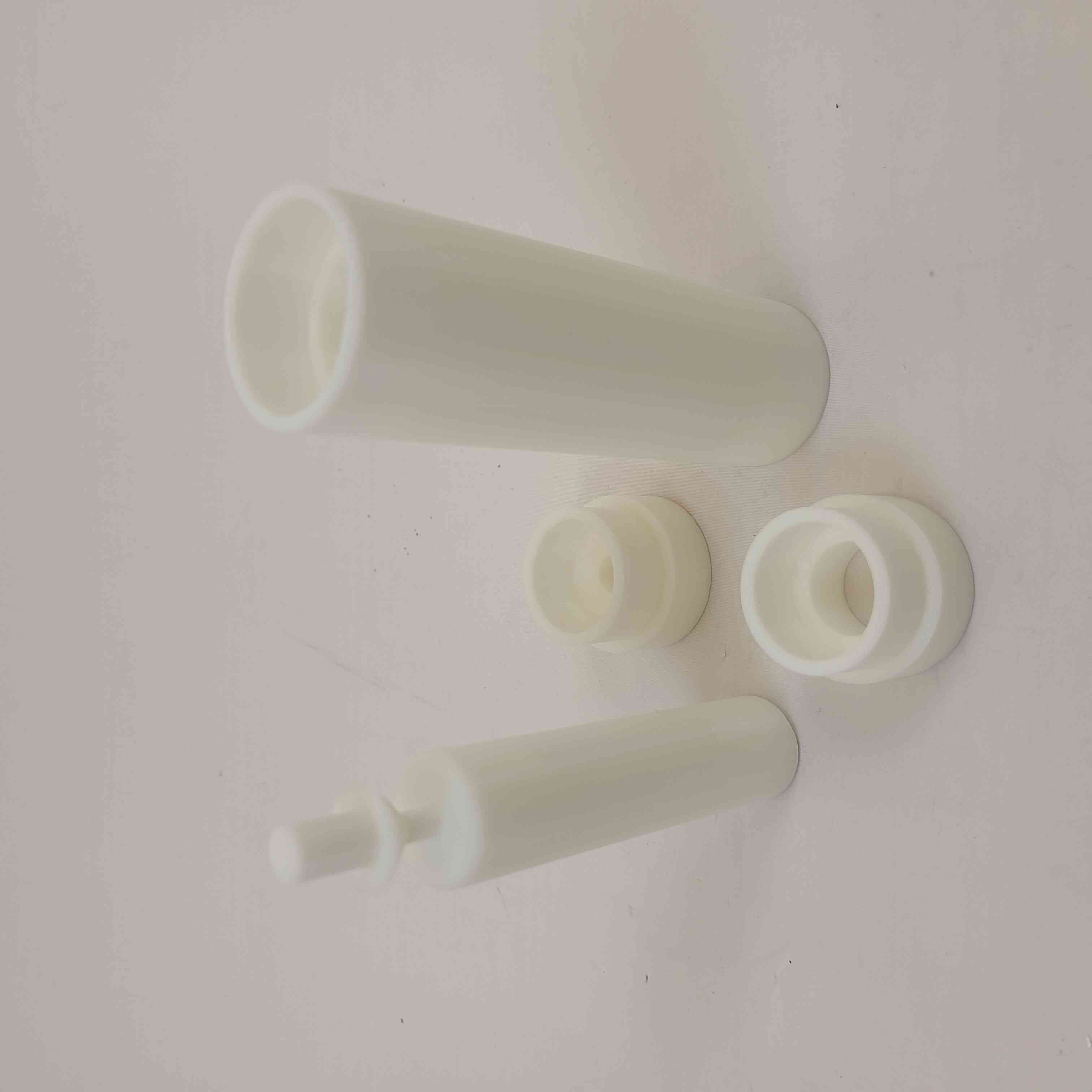
I got inspired by a website called the Soft Robotics Toolkit which described the fabrication of a silicone combustion engine/actuator via a “virtual lost-wax” casting technique. This meant creating an outside shell and an inner core between which my silicone would cure. This process, like the standard lost-wax requires the destruction of the mould after the cast is completed.
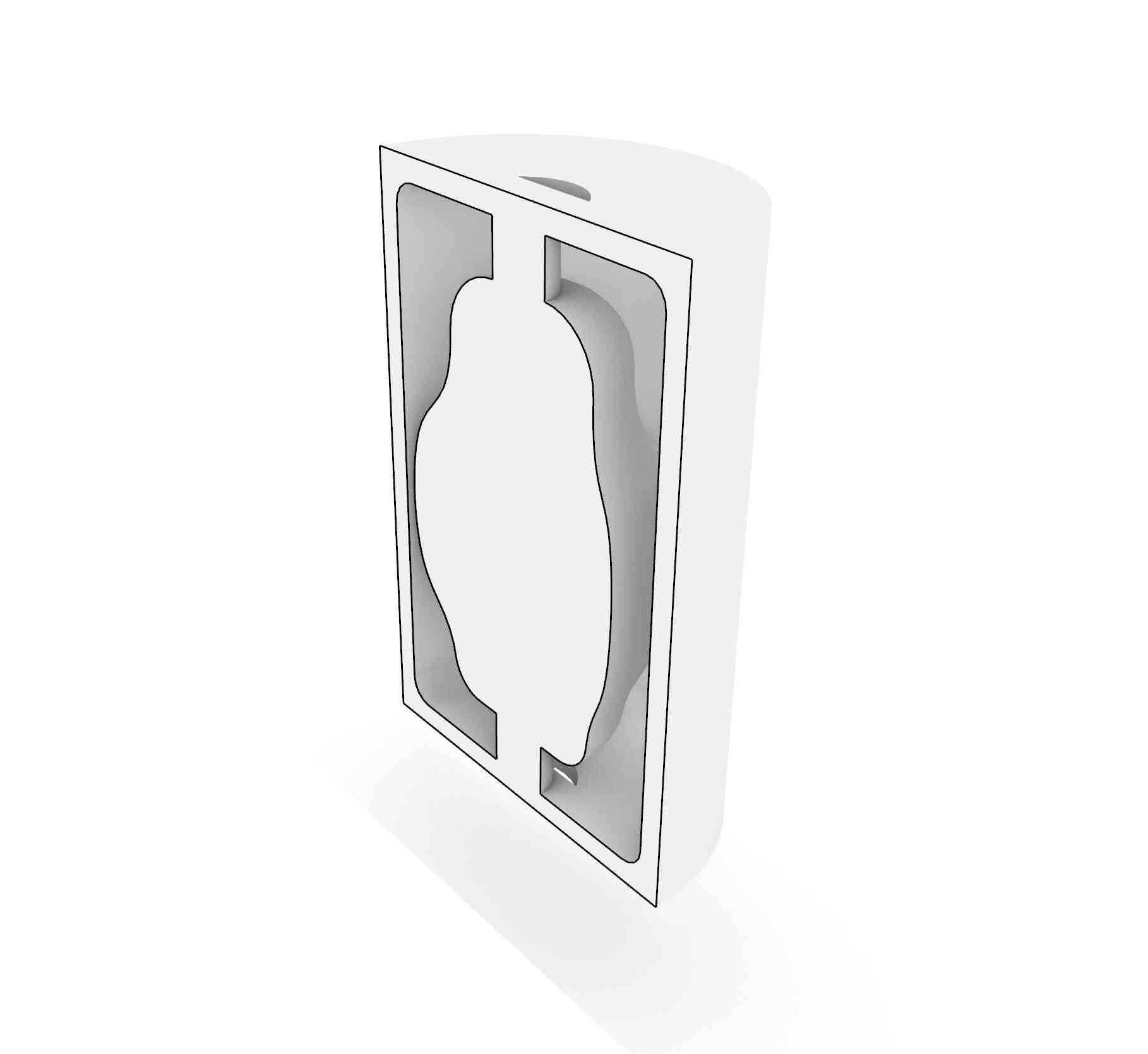
Here’s the Rhino model of the cast. As you can see it is a unified object with a hole at the top and bottom through which the silicone is going to be injected.
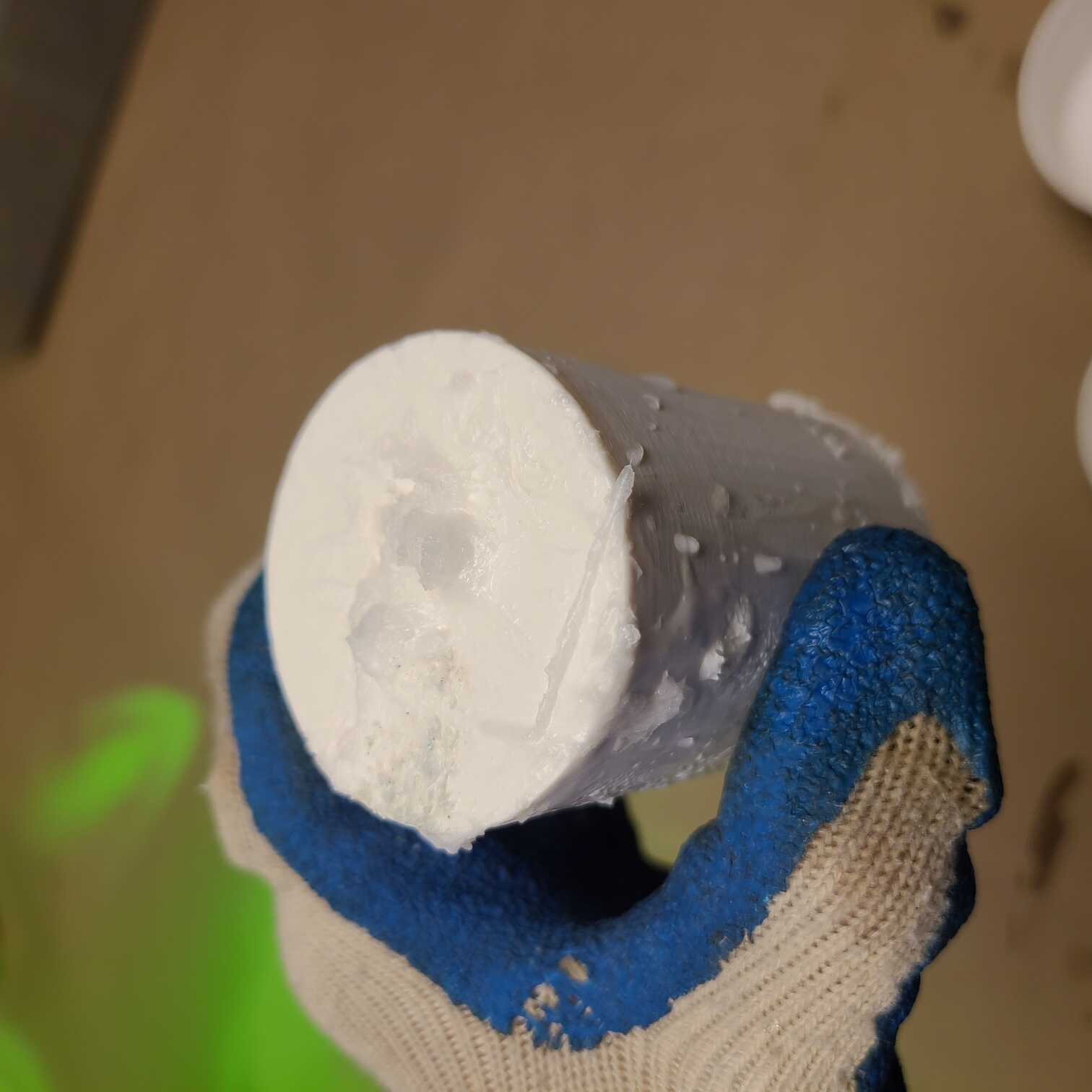
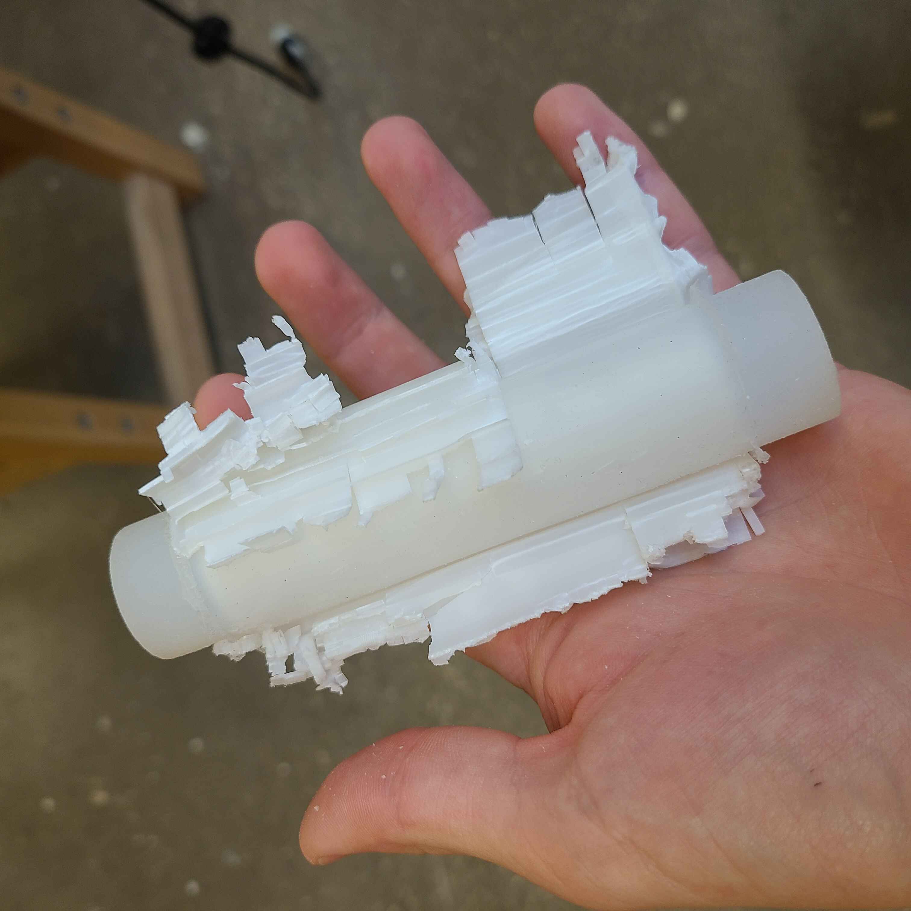
I found out that Acetone is the best way of dissolving ABS plastic and, since it's easy to get a hold of, I chose to use it for my de-moulding. I forgot about the supports on my ABS print (which unfortunately ended up inside my enclosed 3D print) so I tried out the acetone-dissolve trick on them first. This was a bit weird to work with because the acetone would create a sort of sludge that would begin to stick to the mould as well as my hands. I couldn't tell if the supports inside were getting dissolved so I just decided to pour the silicone anyway.
After pouring in the silicone I figured I will have to do another print because I knew this one would be a pain to open back up with acetone.
The first new print came out quite bad. I didn't notice that someone changed the default settings for the speed and amount of material extruded. I was noticing that my surfaces were patchy and would leak the silicone if I used them. I decided to print it all again.
The next print came out much better and I could start assembling the mould...
After assembly I got down to casting. Always make sure you measure out how much silicone you'll need! I had to rush to get a second batch prepared so that my cast wouldn't set.
The cast came out a bit patchy but ok. I’ll have to cover up some holes and get down to testing how it inflates. More on that in the future!
Moodboarding
O'Neill Cylinder
This may be the least actionable inspiration but I think it captures the sense of adventure and grandeur of human space exploration. This habitat, located in one of the Earth-Moon Lagrange Points, could house tens of thousands of people and be completely autonomous to Earth.
SOM Moon Village and Hassell Mars Habitat
Next up, SOM and Hassell with their own take on inflatable human habitats on the Moon and Mars. These projects are more achievable in the short term and that is why they suggest solutions for actual design challenges. I want to incorporate their respect for functionality and realism but venture a little bit out into the speculative with my design.
Bigelow Aerospace and TransHab
TransHab and its adaptation by Bigelow is the next (and even more realistic) approach to using inflatables in space. I’m interested in their analysis of materials and layering necessary to provide protection from the harsh space environment.
Frei Otto
Bringing it down to Earth and a little closer to the architecture I’m used to is Frei Otto and his studies of tension structures. Tension is going to be the main force exerted on habitats on the Moon. It is important we lean into its efficiencies and the opportunities it provides. I want to explore Frei Otto’s work to inspire my form-finding exercises and structural calculations.
Soft Robotics
Lastly, soft robotics. This is an inspiration that zooms in onto the actual fabrication technique that I might use for my flight-ready prototype. I want to experiment with casting silicone to create inflatable membranes that will allow me to precisely control the form of the structure based on pressure.
---
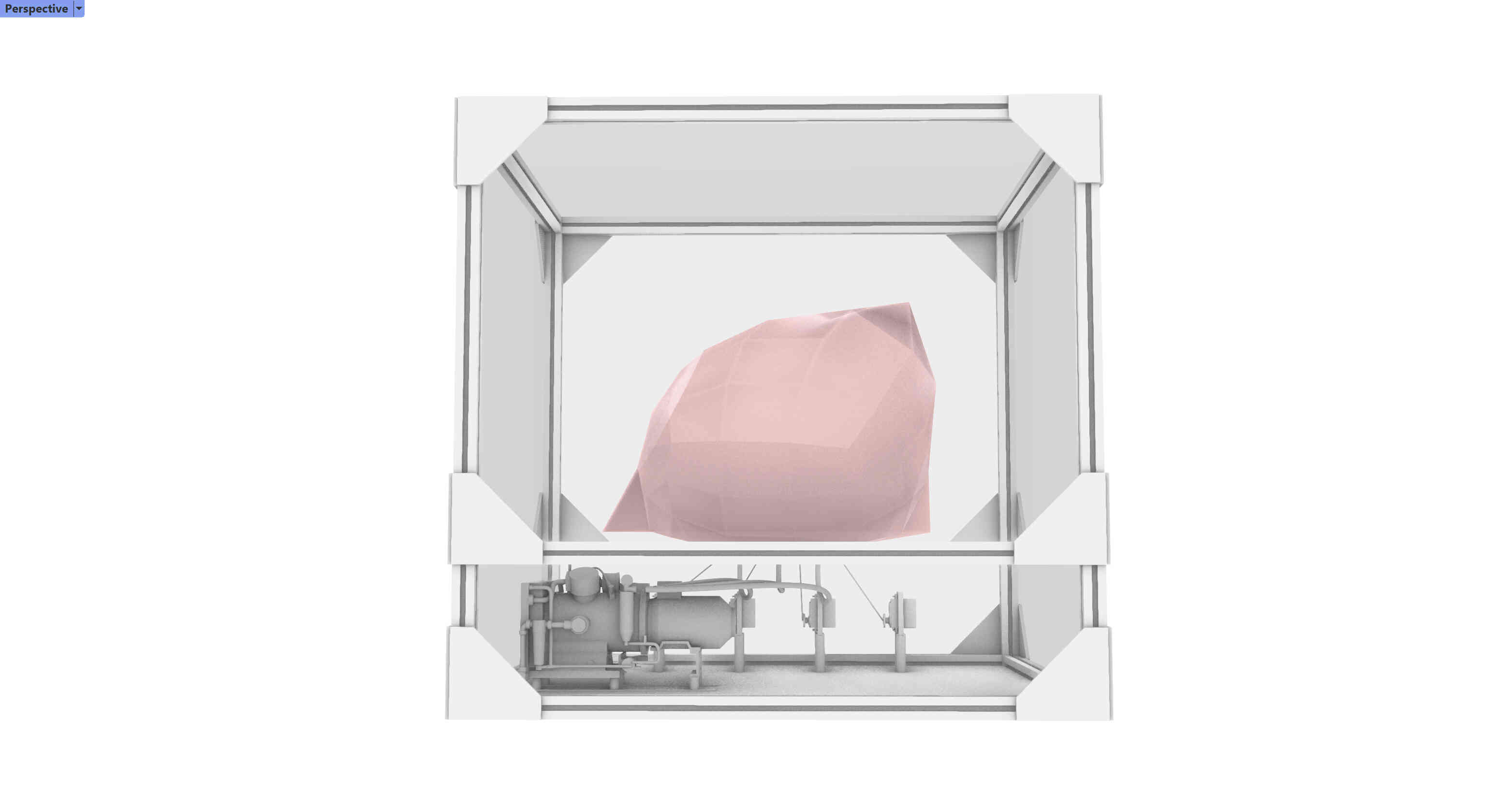
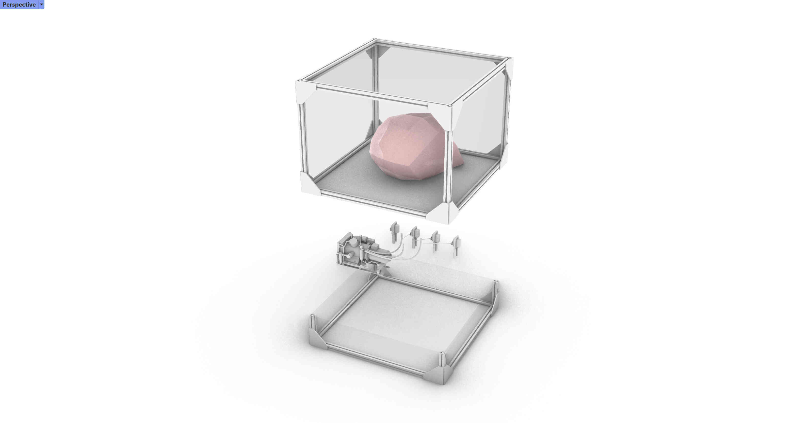
I’ll leave you with the screenshots of the basic set I have going on right now for the prototype. Way more work has to be done to finalise the shape, the systems and the ultimate model, but this shows the inflatable up top with compressor and servo motors controlling tension members below.
Creating an Air Pump PCB
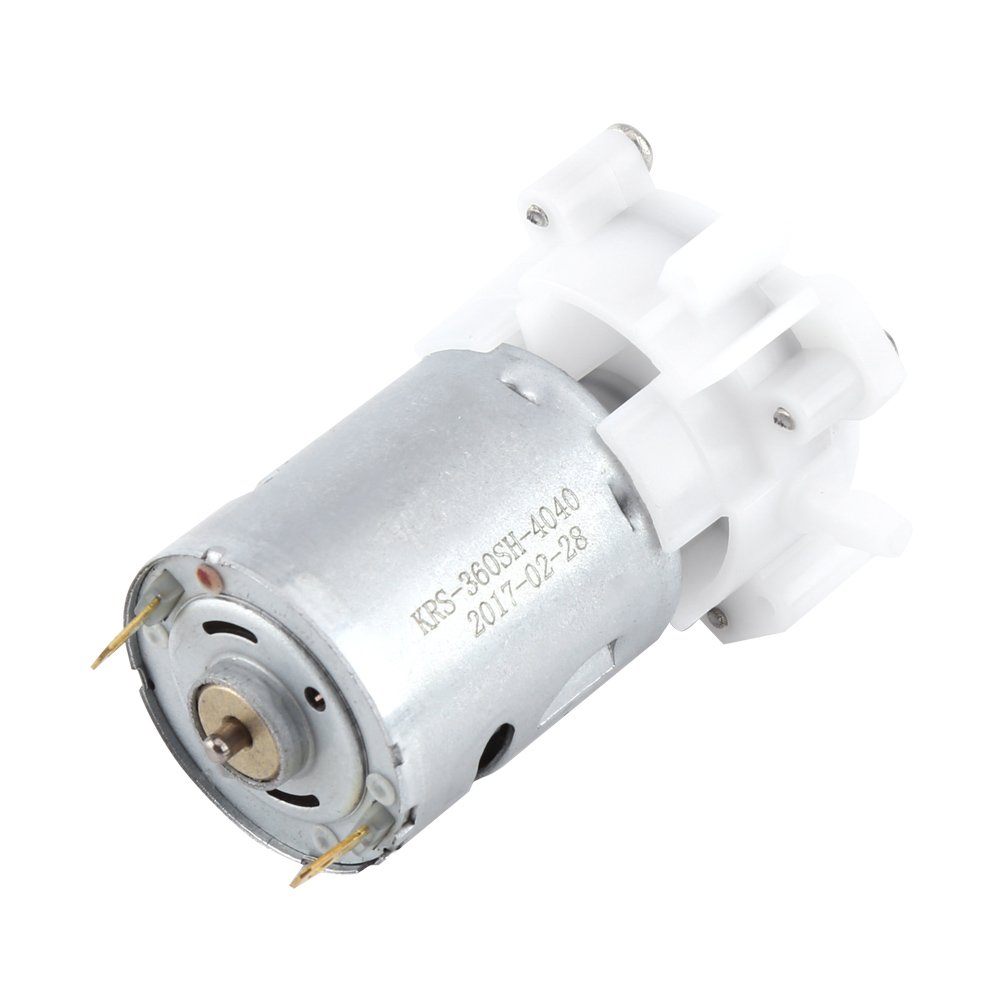
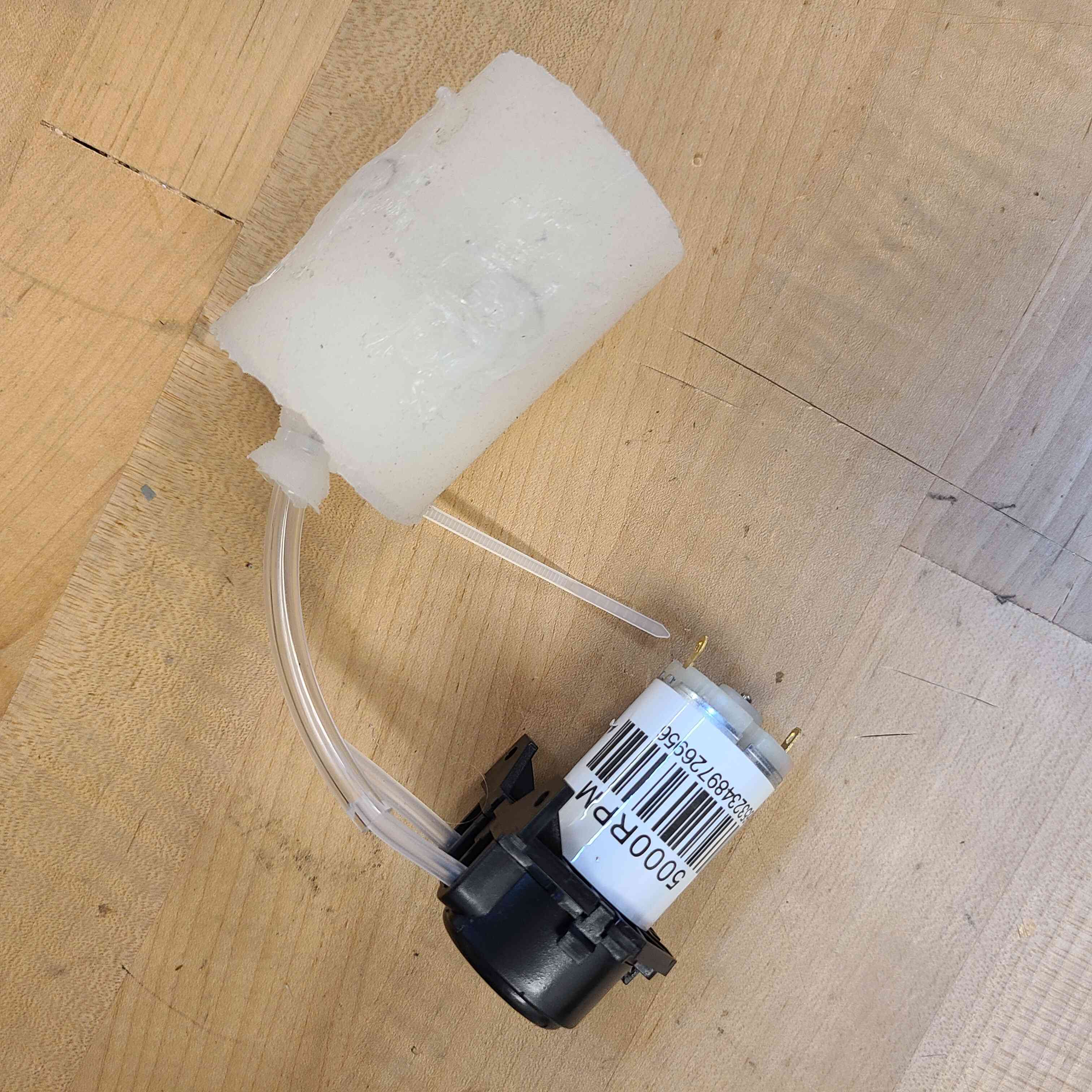
This week I want to try and make a circuit that could power an air pump with a press of a button. The pump is a small 12V aquarium pump (model KRS-260SH-4040). The input voltage can be anything between 3V and 12V but a 5V 2A power supply is recommended (computer USB). The pump looks like this:
I want to try using the SAMD21E microcontroller due the larger number of available pins. I don’t know if this is the correct way to go about this, but I have a hunch I’ll want those pins in the future. Also, I might learn some more in the process.
Back to the motor for a bit, I think it may be a BDC Motor (yes, it is a BCD - a Mabuchi Carbon-brush Motor. I also read somewhere that it might be necessary to implement a capacitor next to the motor since its free draw is around 1.72A where its peak draw at the beginning is 3A. I guess I will be compensating for the 1.28A…?
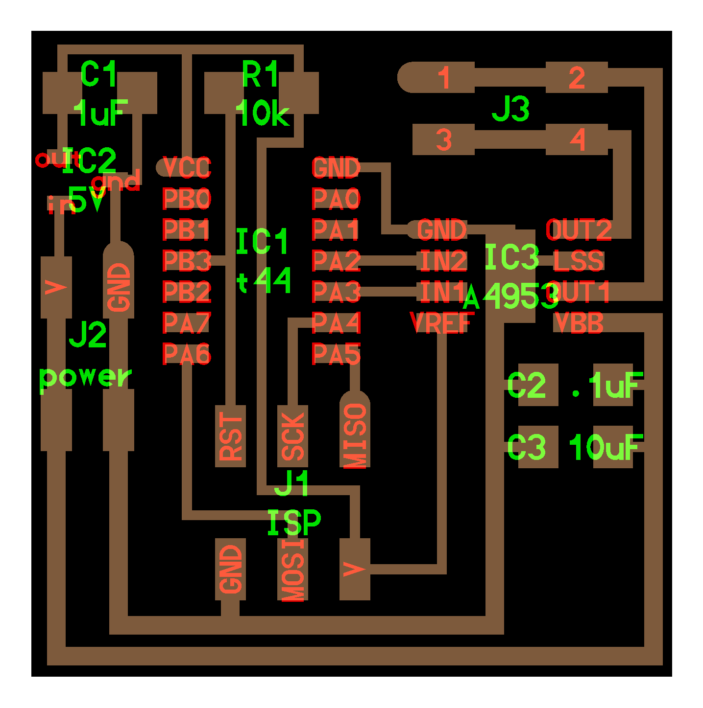
Now, about the PCB I need to make. I was looking at two board examples that might be of assistance to me. First the hello.H-Bridge.44 from the Output Devices week. This one uses an ATtiny44 MC, but I hope I can use the same connection logic in the SAMD21E like in the example hello.D21E.echo from the Embedded Programming week.
I went to the EECS workshop to get some help figuring out the marriage of the above two boards. I received a good explanation of how MOSFETs work and how they are applied in an H-bridge to get the motor to spin clockwise and anticlockwise. Basically, you have two P-MOSFETs closer to your power source and two N-MOSFETs closer to your gnd. P-MOSFETs are ON when its gate (what connects to a pin on a microcontroller) is LOW – ie there’s no voltage. It is OFF when the gate is HIGH. N-MOSFETs are the opposite; ON when HIGH and OFF when LOW. On your MC you then have four pins that individually control the 4 MOSFET gates with the intent that current flows from the power source, through the top-left P-MOSFET, through the motor (spinning it clockwise) and then through the bottom-right N-MOSFET and off to gnd. If you want to spin the motor counter clockwise you go power source > top-right P-fet > motor > bottom-left N-fet > gnd.
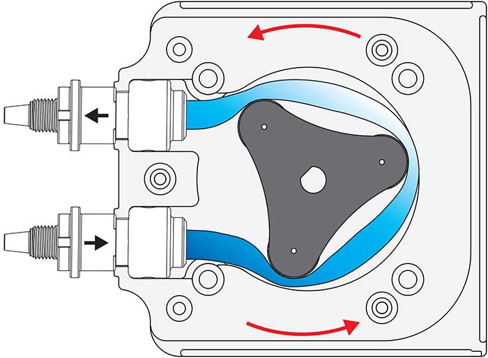
During the Office Hour I also spoke about sizing correct voltage regulators (100mA not 1A), more convenient header pins (2.54mm not 1.27mm), some general schematic-drawing trivia and, most importantly, getting the correct motor for the job – ie. making an inflatable building which you can control. Apparently the pump I have shown above is totally not going to cut it and I need a peristaltic pump, which are often used in medical and pharma solutions. It looks like this:
Instead of having blades (like what my pump probably has) and allowing the air to escape after the pump has been turned off, this one has a rotating constrictor that both pushes air one way or the other, but also doesn’t allow it to escape after it has been turned off. I’ll have to order one to test it out, but it looks promising. I nevertheless am going ahead with the same set up for my PCB since a small peristaltic pump will also run on a 12V BDC motor.
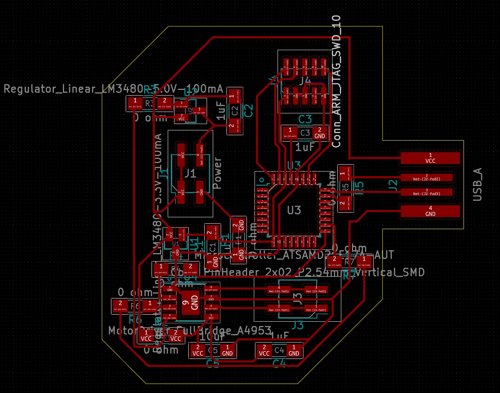
So I applied what I learnt to my KiCAD schematic. With my new understanding the process went a little smoother (though not silky smooth) and I was able to pick and place components with more confidence.
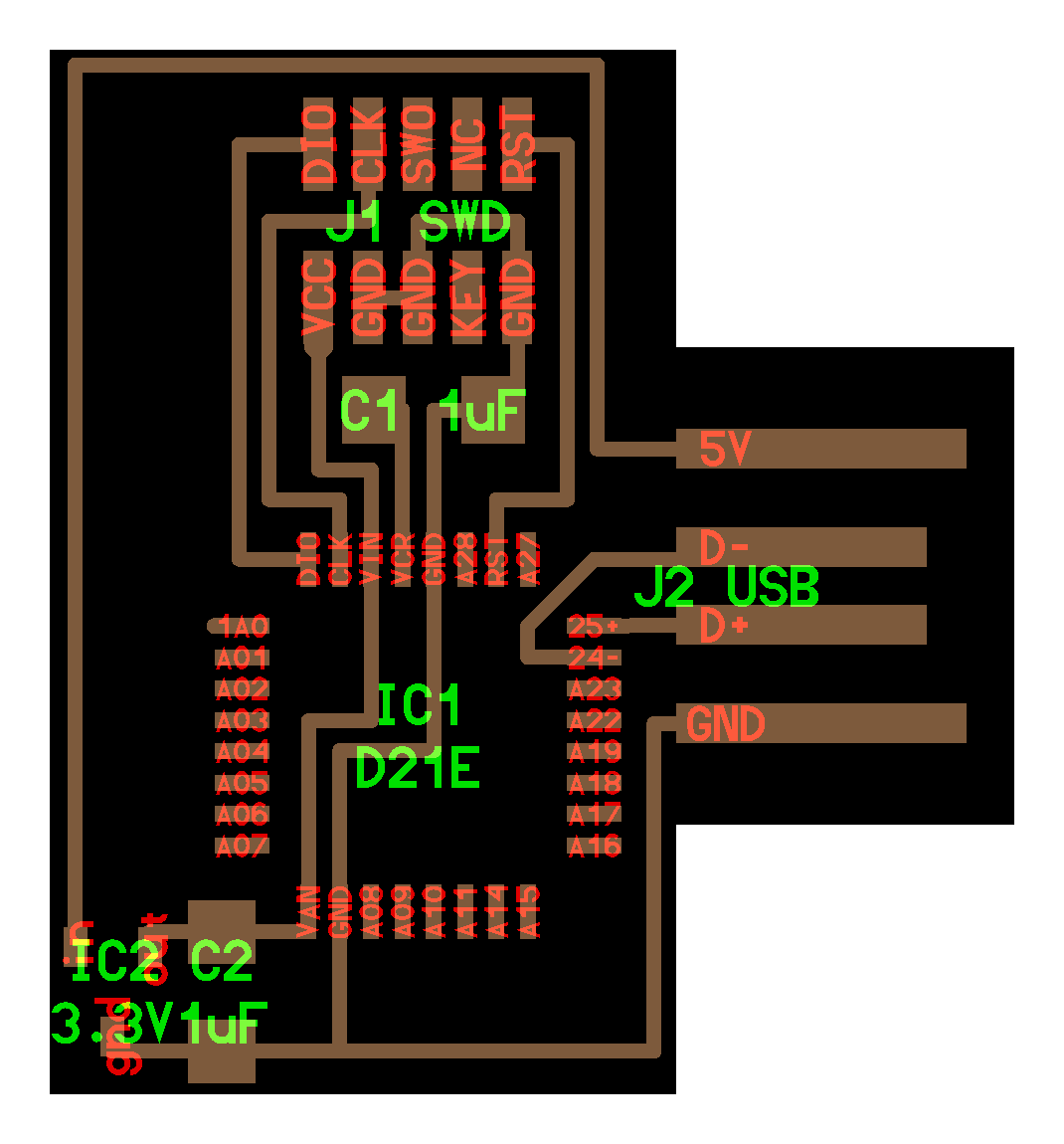
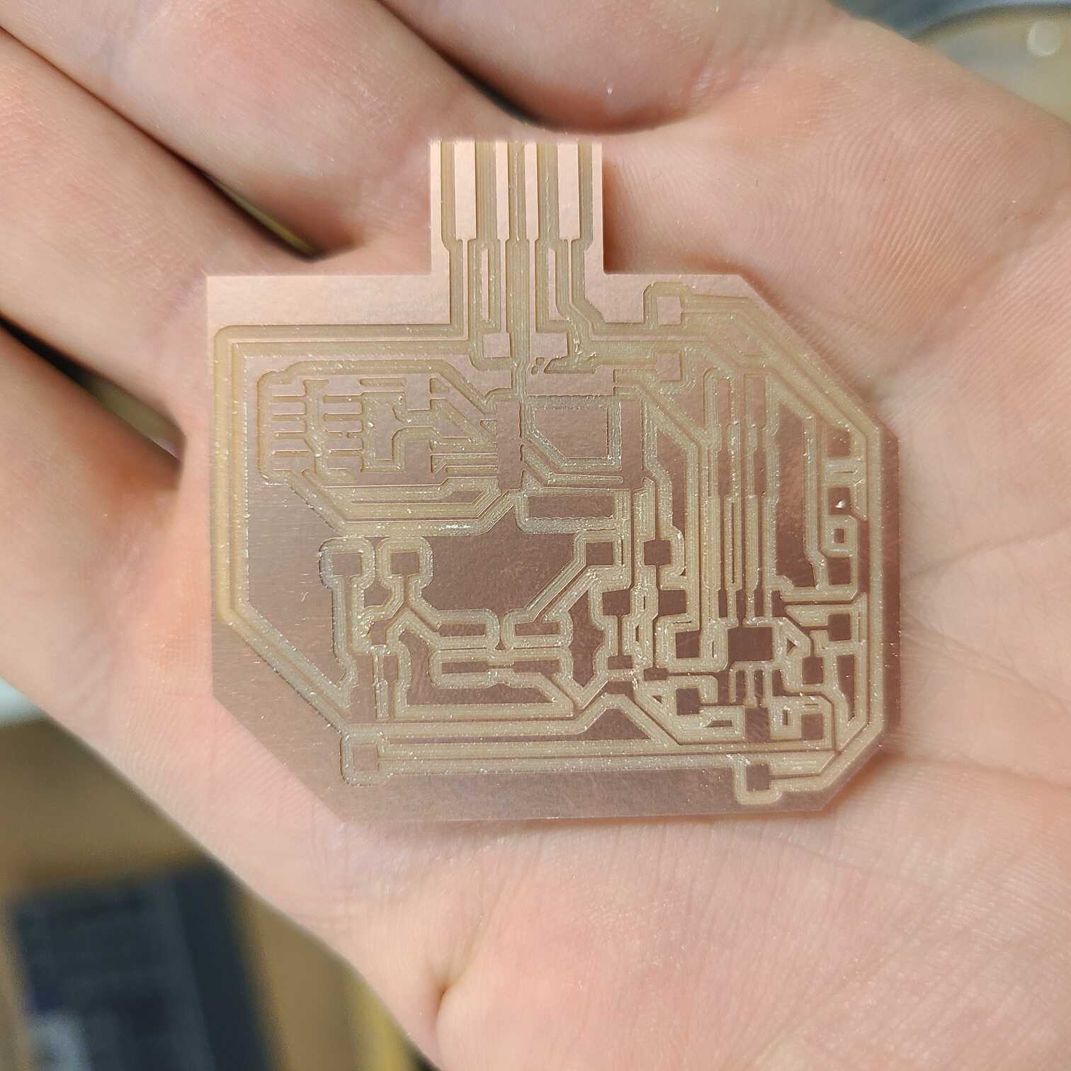
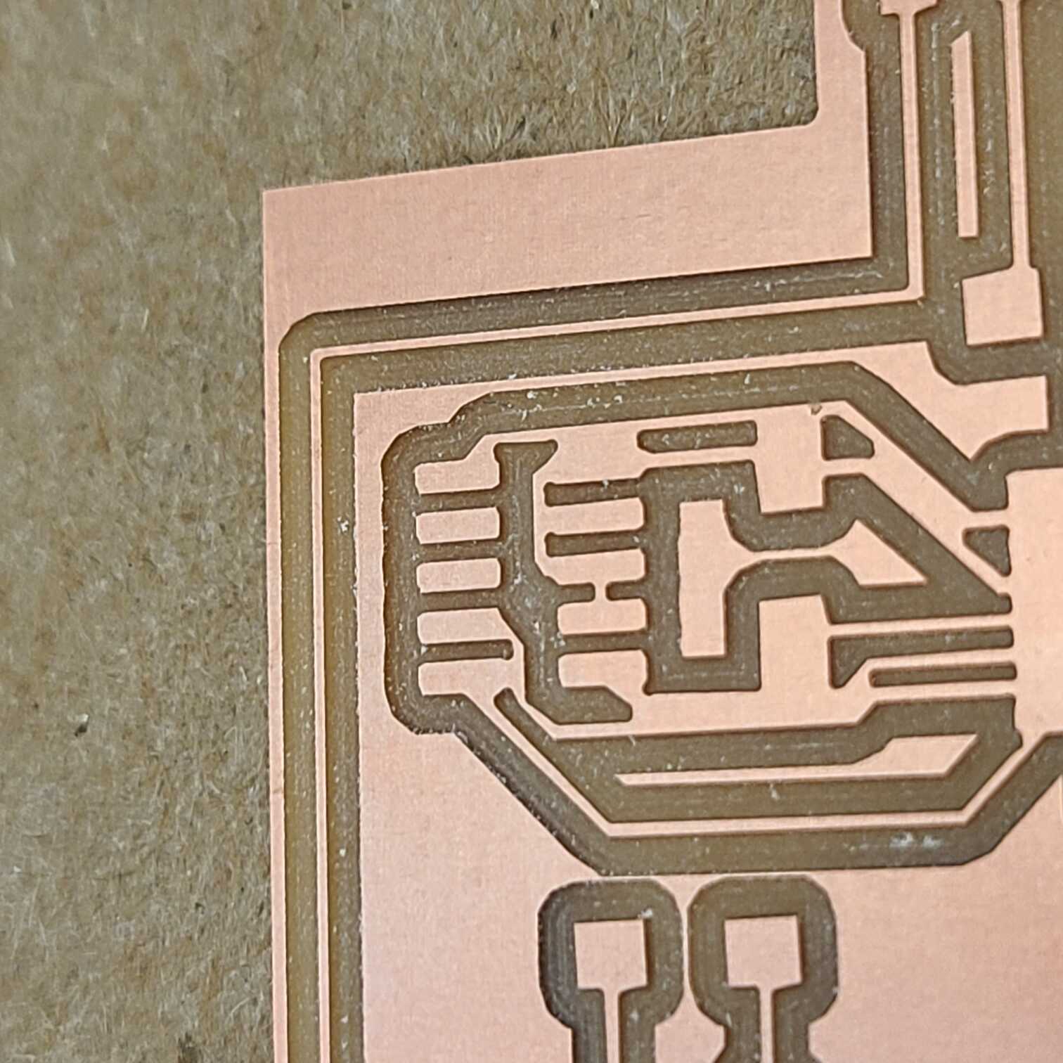
And here is the board view of my PCB. A bit messy on the traces, but it seems to do the job. It’s worth noting (and you’ll see why in a bit) that I had to reduce the clearance and trace width properties in the Board Setup from 0.5mm to 0.3mm because the SAMD21E has such tight spacing between its pads that KiCAD refused to draw my wires. And now to the failure…
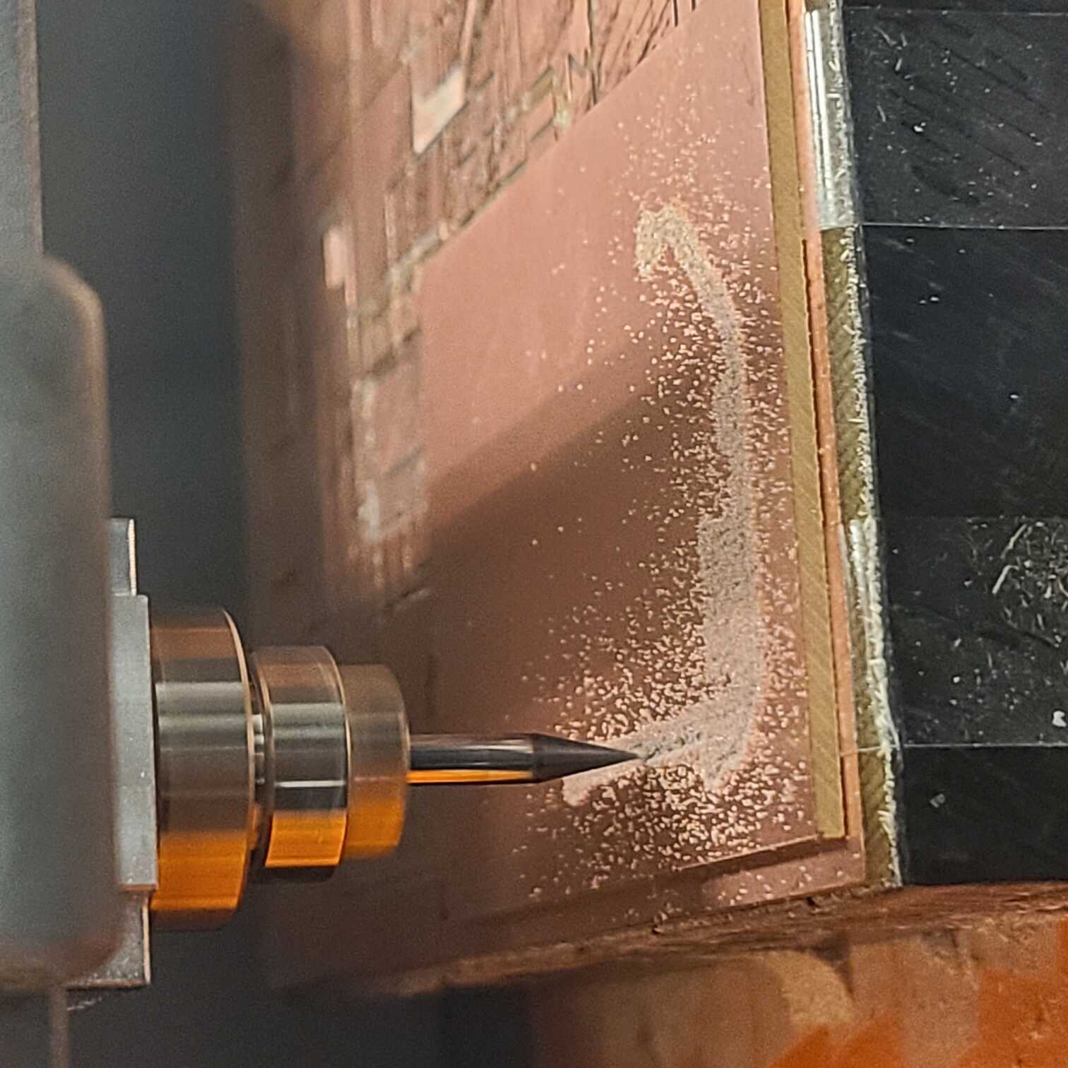
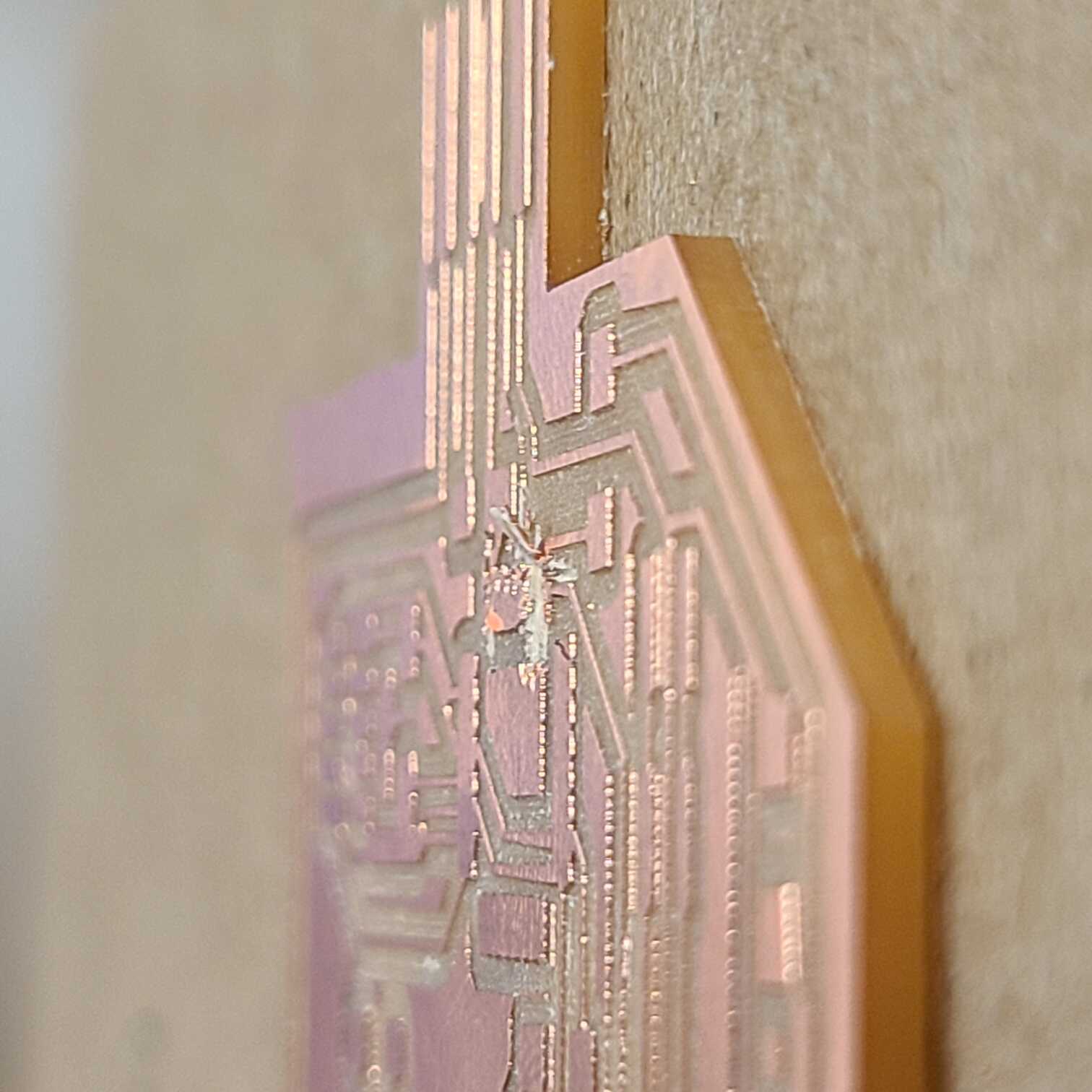
All was looking fine, the mill did some cutting, I did some vacuuming and viola, a board. But then I looked a bit closer and I saw that some of my traces came out connected to adjacent ones. So did my SAMD21E pads. I tried sculpting away the excess with a knife, but second pad in I ejected a vital piece of copper off the board making my entire PCB basically garbage
Preparing for the Zero-G PDR
Time for the Preliminary Design Review! I was a little surprised by the level of fidelity required for this review when I first read the PDF, but I’ll try my best to squeeze out the most complete product I can.
I’m writing this as I go along with my thought process so it may be a little rambly but hey, it’s a blog post in the end!
Anyway, here’s the list of things we need to prepare:
Overview, purpose and merit for me is the idea of all lunar habitats needing to be pressurised. I want to test whether you can have intuitive and useful control over the habitat’s form by inflating purpose-designed membranes or tensioning cables. The idea here is that the habitat would bend in expected (or maybe unexpected?) ways and could modulate the distribution of interior spaces.
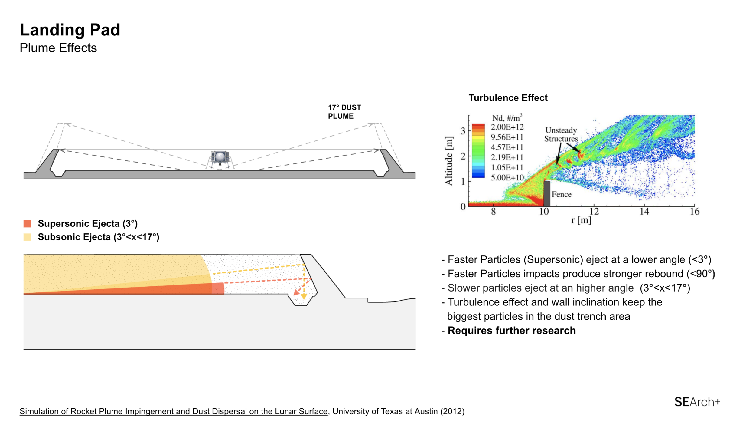
However, I’ve received comments about having too loose of connection to zero-g and that I need to re-establish it in order to have a successful project. This is fair since my project is an architectural model attached to the ground and will not be doing anything cool or useful floating in mid-air. Ever since receiving these comments I’ve been thinking hard about staying true to my desired brief but augmenting the project so that it uses more of the unique affordances of lunar gravity. I was ultimately inspired by the challenge of preventing rocket plume ejecta from damaging nearby infrastructure. Building landing pads with blast walls can be extremely time-consuming, but, if we took into consideration the shallow spread of ejecta (3 degrees for supersonic particles, 17 degrees for subsonic particles) then maybe we could avoid the ejecta instead?
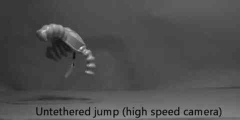
Instead of waiting years to sinter blast walls can we use rapid pressurisation to hop over incoming ejecta like this soft robot below?
So I read some journals and made some adjustments to my final design...
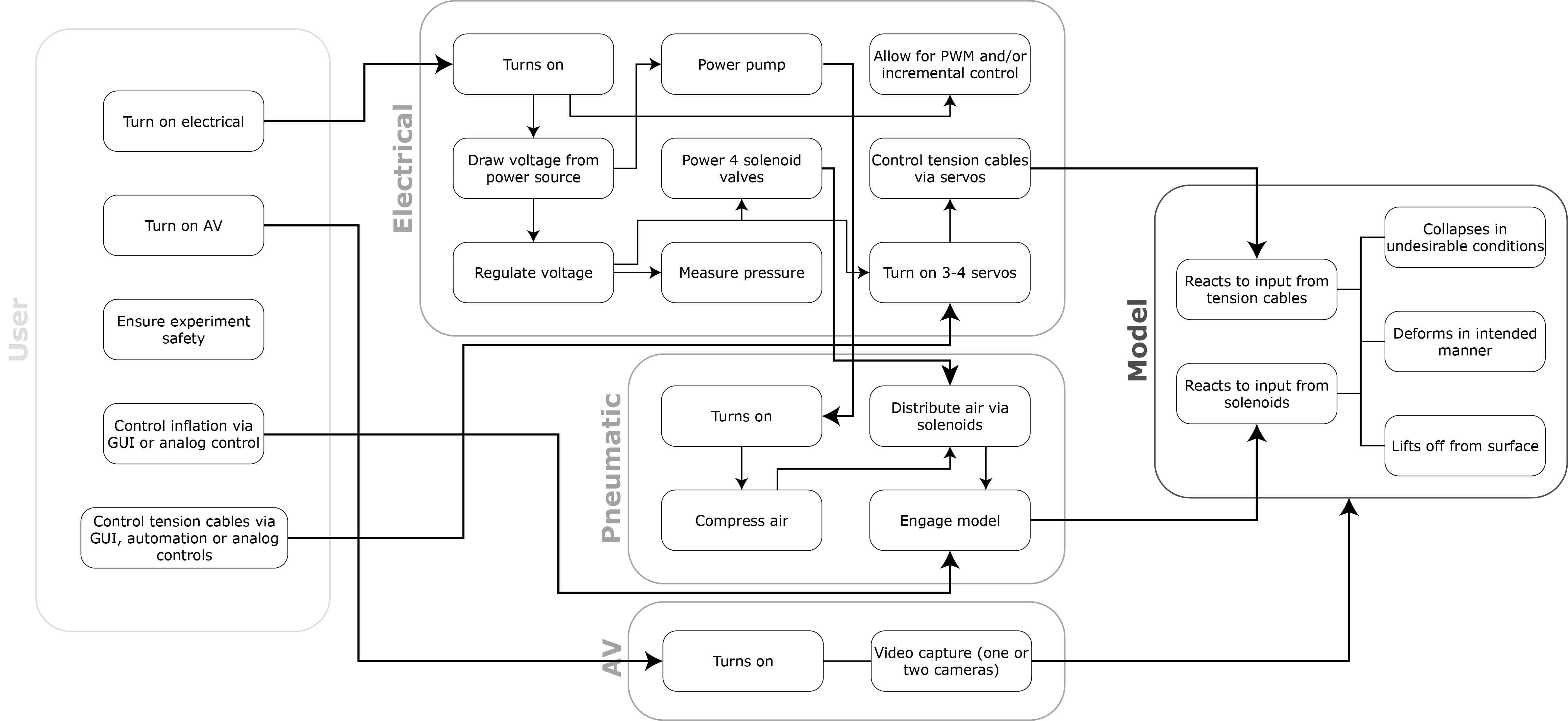
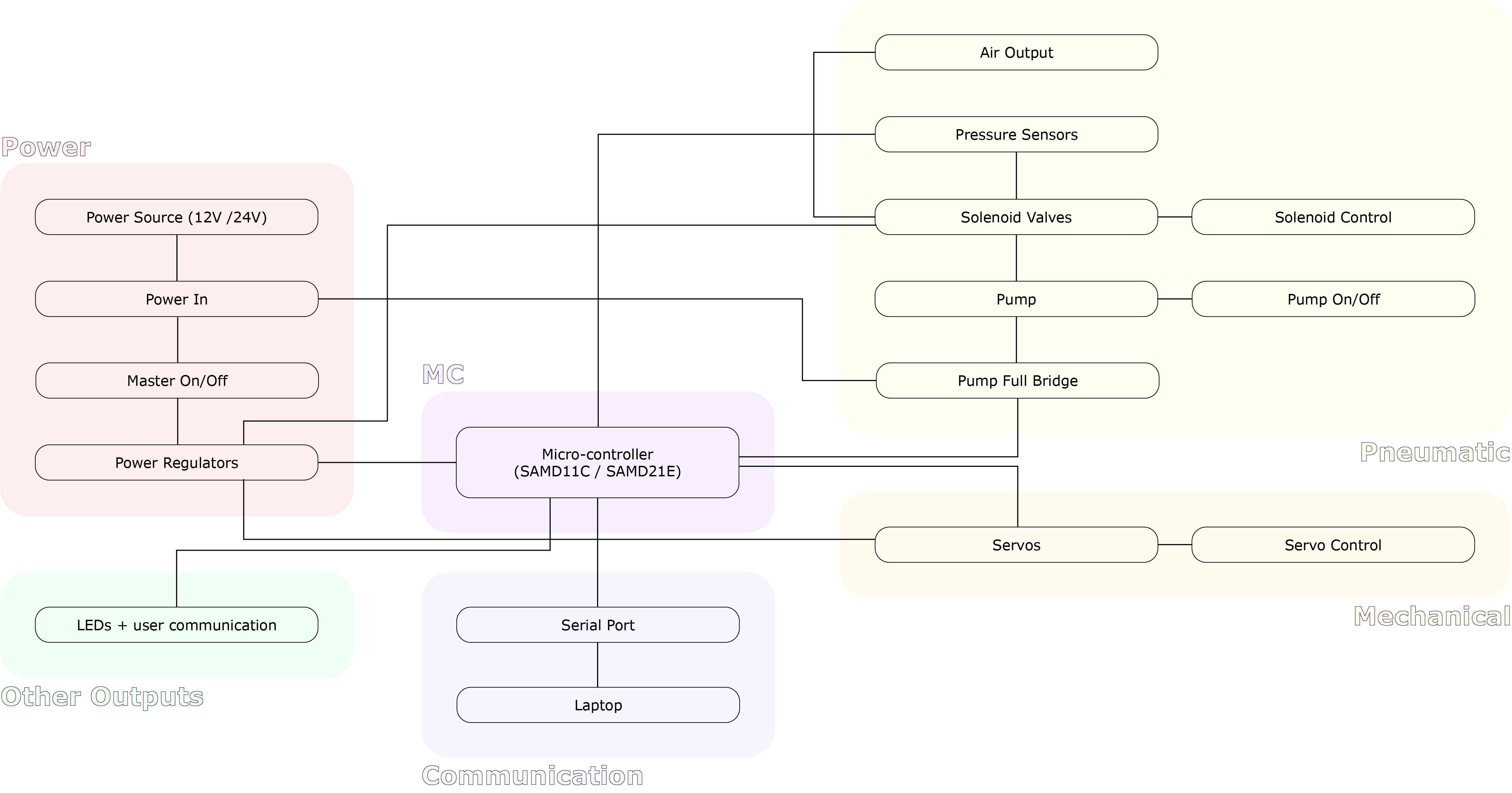
I also produced a System Block Diagram:
And a high level electronics schematic inspired by the Soft Robotics Toolkit Control Board
I'm running out of time!!! GO TESTS!
^^^ This guy really didn't want to work
^^^ That one was a little more cooperative
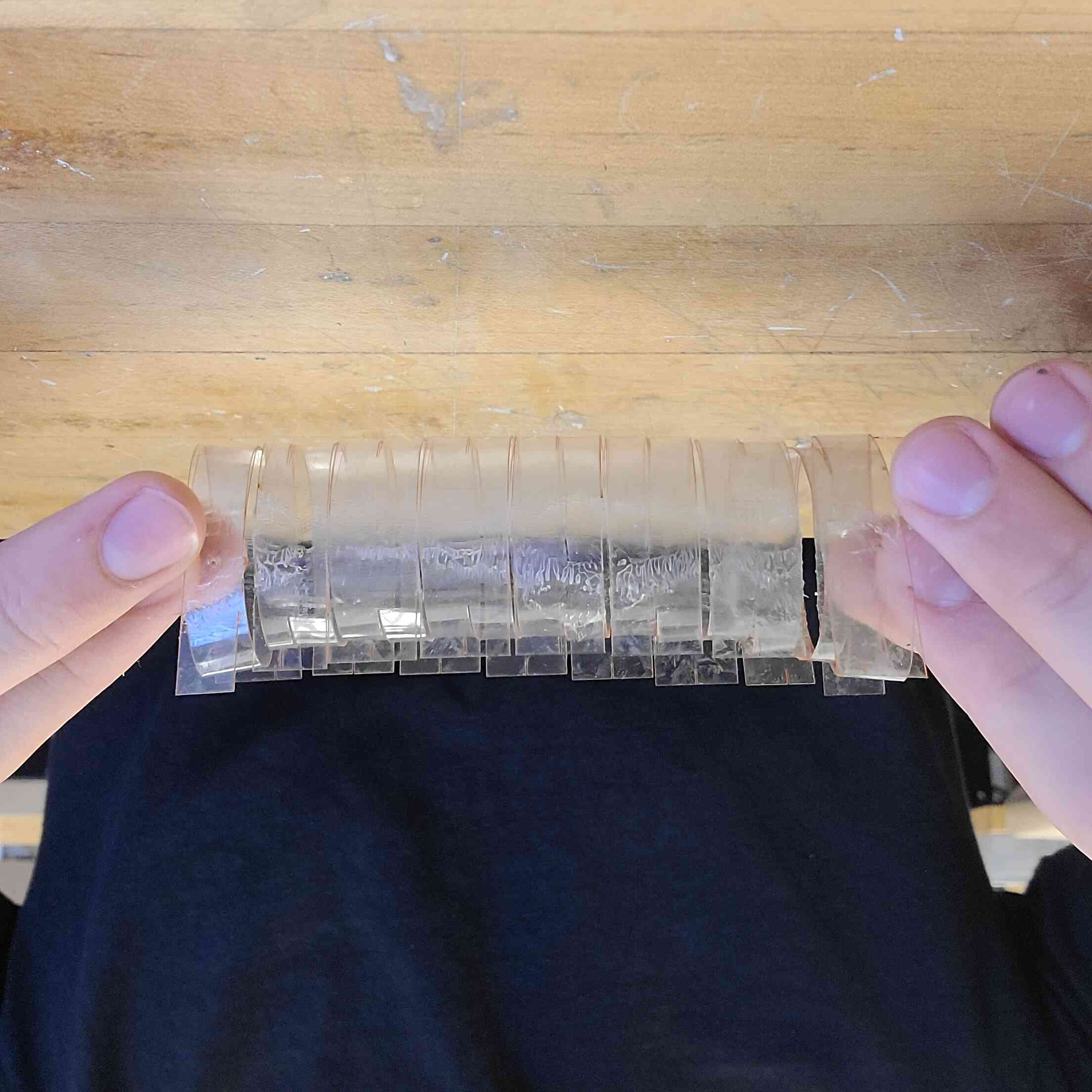
^^^ Need to run tests on this one still... had some technical issues with delamination
---
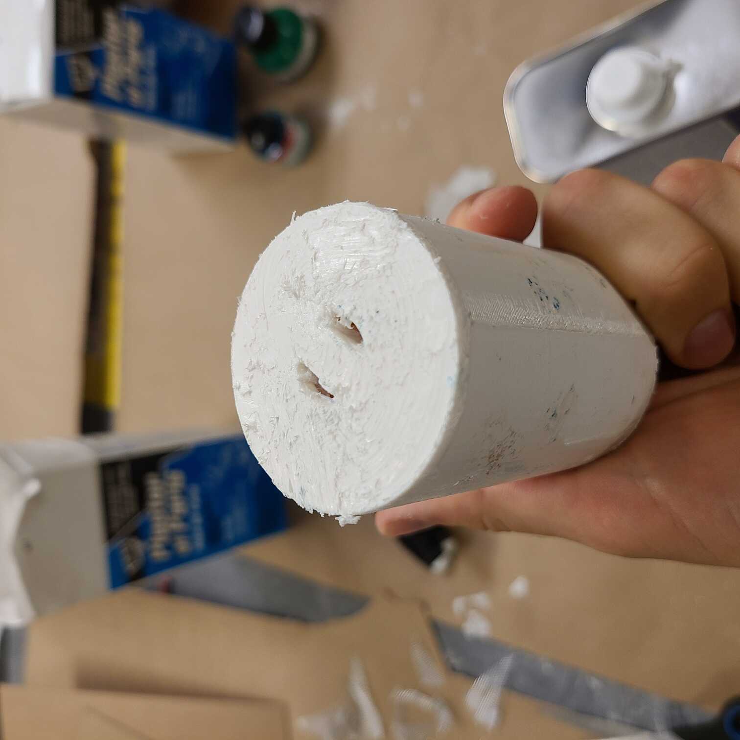
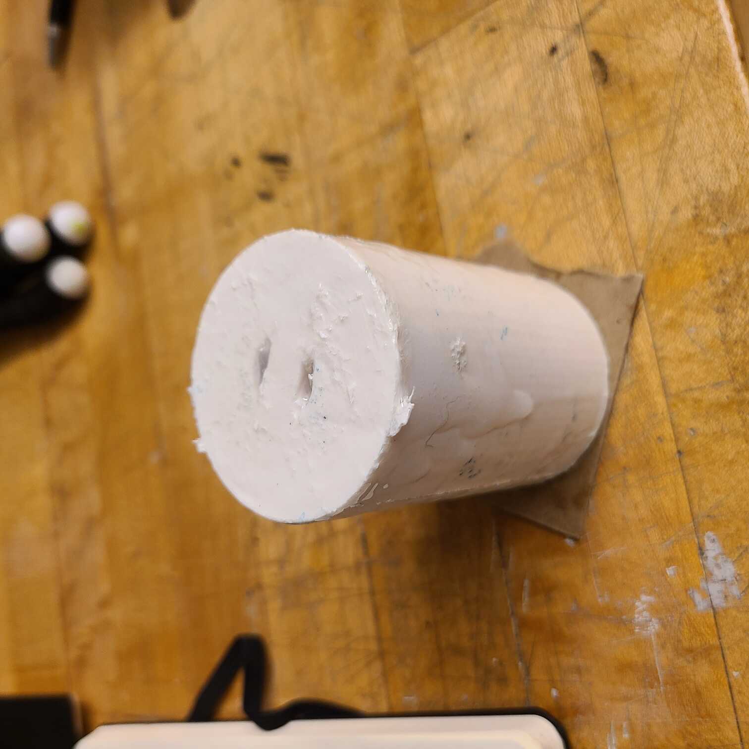
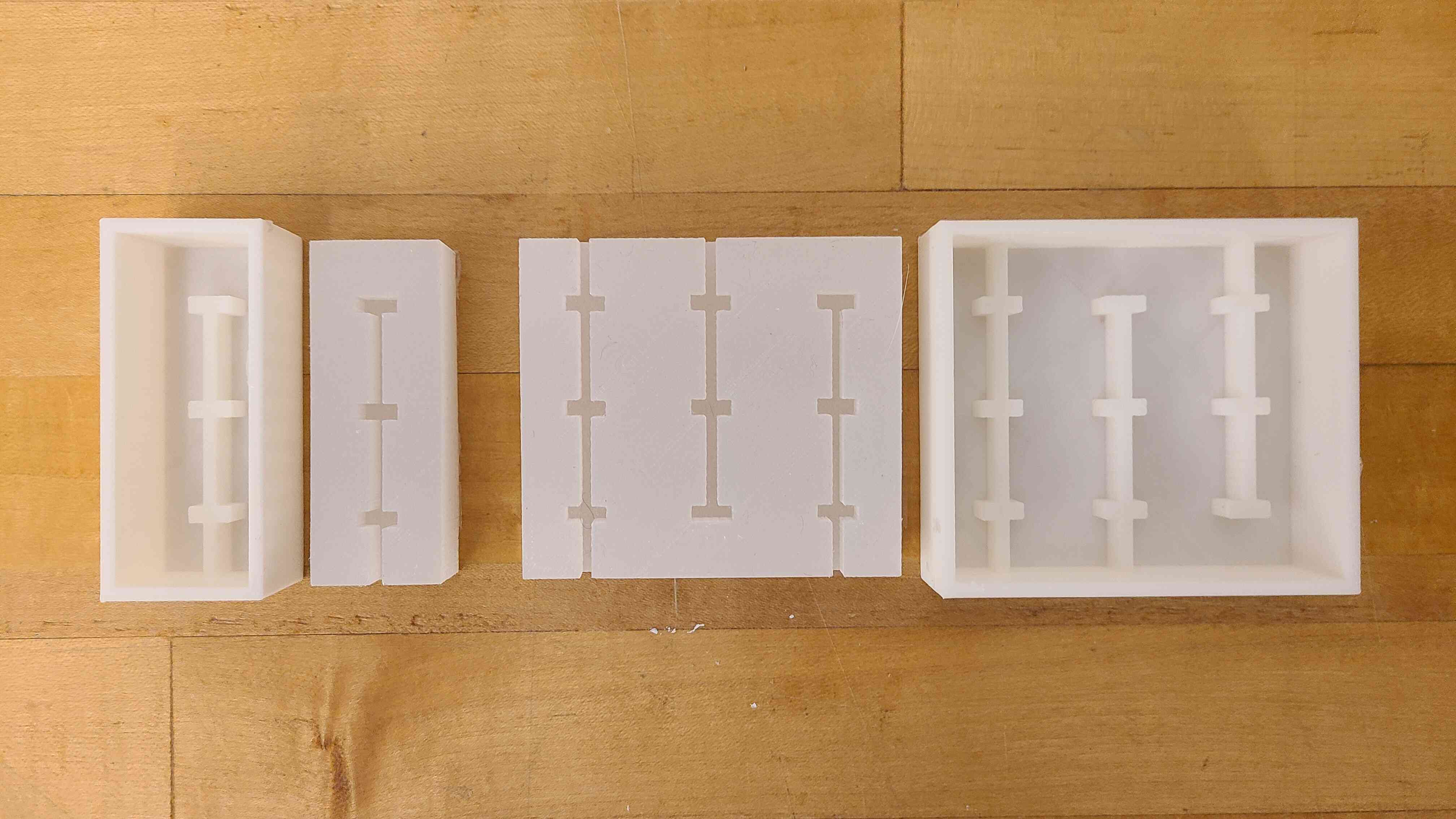
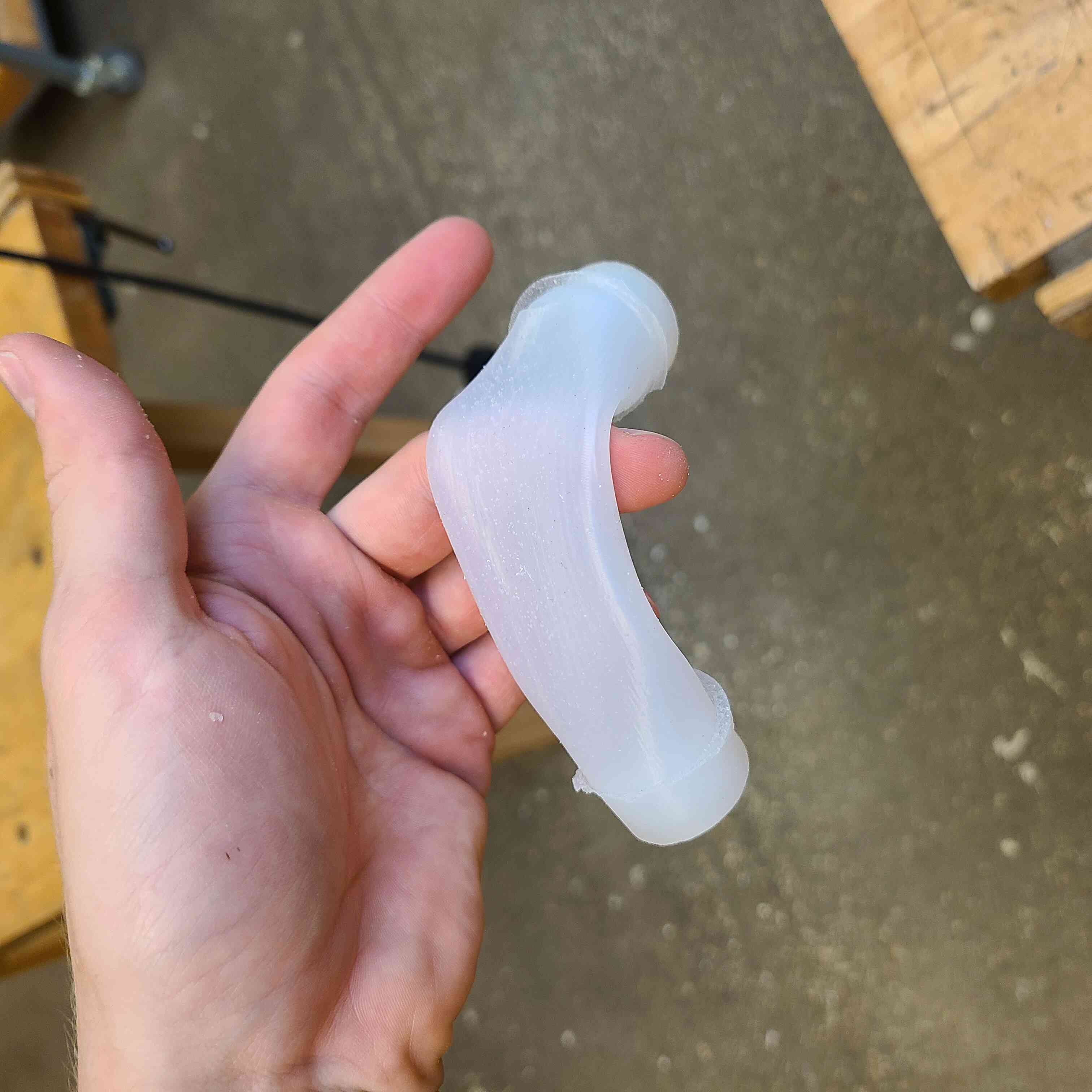
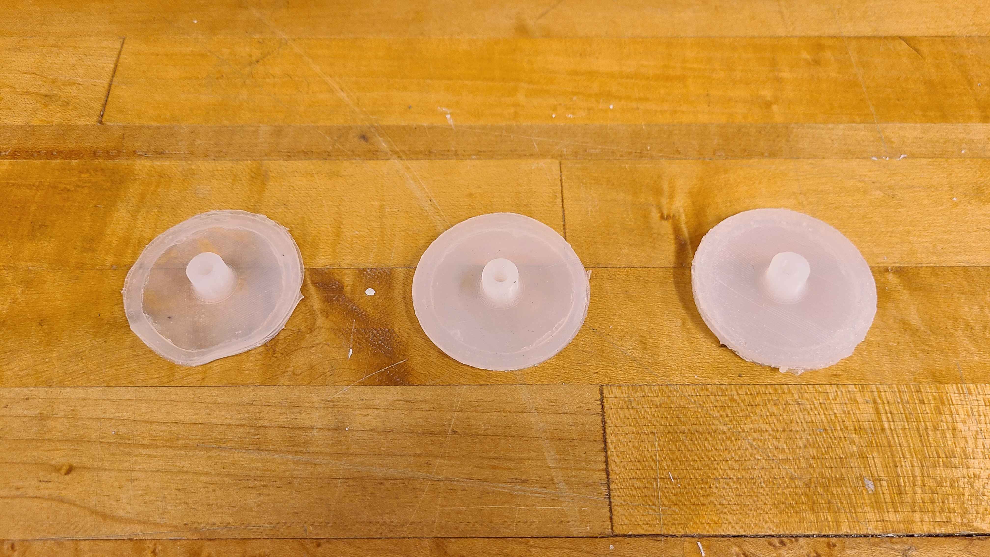
Hi, it's me again. It's been a month or so. That is why I'm using 4 "br's" instead of 2. So what's been going on? I didn't actually run any tests on the aforementioned silicone actuator. I bumped into an interesting paper by Ni et al (google it: A Jumping Robot Using Soft Pneumatic Actuator) and decided that if my thing is to jump over lunar blast ejecta it needs something more than an silicone dildo that can extend an extra 40% of its original length. With this in mind I decided to design an actuator inspired by that paper's proposal:
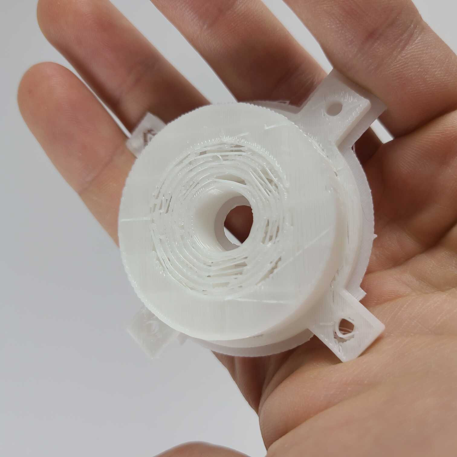
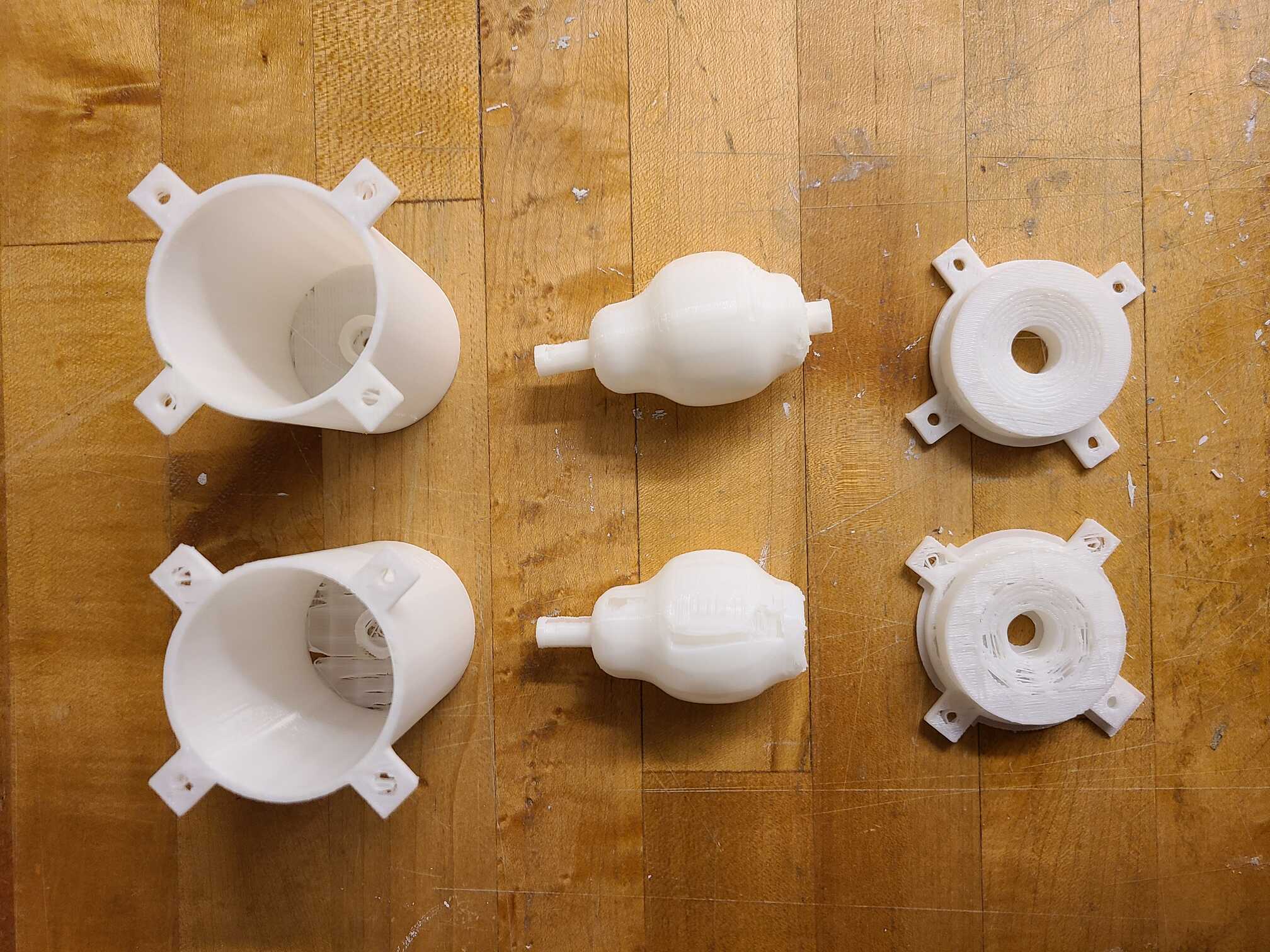
So what do we have here? Well, the actuator is cast as two separate pieces inside two slightly different 3D printed molds. It has an actuation chamber of 50mm and a range of thickesses from 1mm to 3mm. The way it works is that you plug a tube into its top, pressurise a volume of air before a valve that you're controlling and, when you're ready, give it a quick burst of high pressure air that infaltes the membrane and send the thing flying into the air.
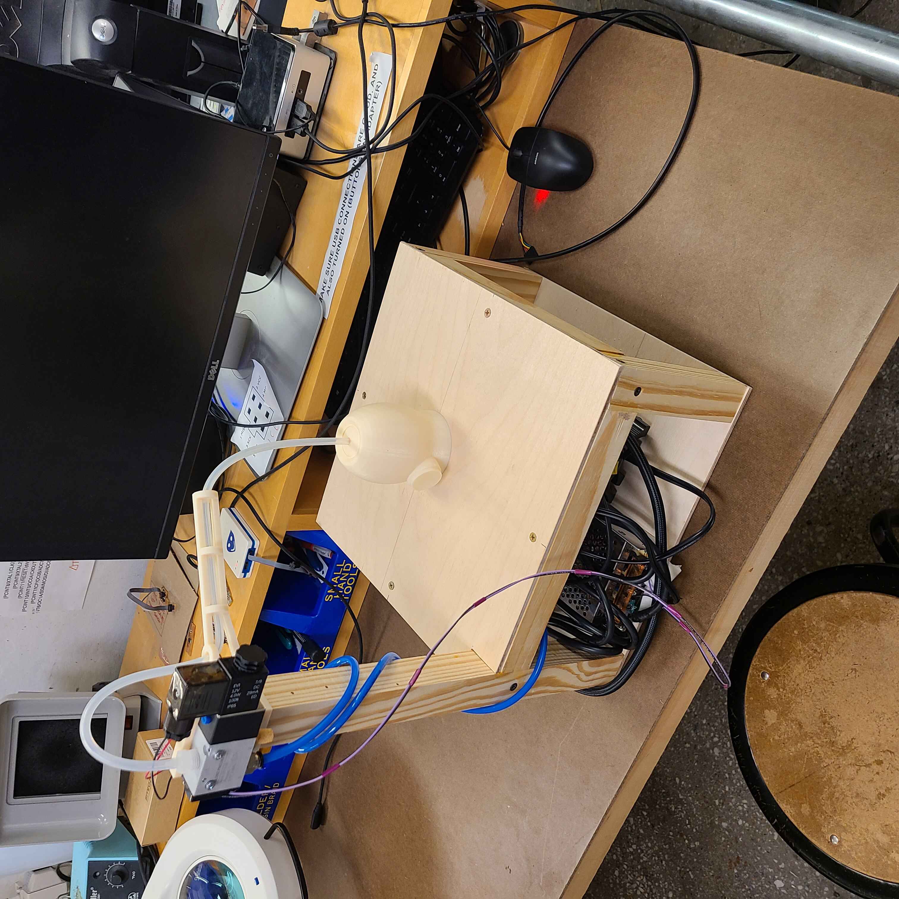
I hear your questions: "but does it work???" The answer is yes, yes it does work. But first, the set up:
In this video you see a bunch of things. First I had to get an AC-to-DC power supply that spits out 12V at a max current of 15A. This then plugs into an air compressor I got off of Amazon that is capable of hitting 70 or so PSI of pressure. I was initally sceptical that this would be able to fill my pressurised volume quickly enough to be able to perform an experiment once every 30 seconds (it's a device that'll be flown on a zero-g flight remember and there each parabola last only about 20 seconds) but after a quick time-to-fill calculation with my known volumes and the compressors 1.06 CFM flow rate I was able to compute that it'll only take 2 seconds to fill my pressurised volume. Easy peasy.
Where was I? Ah ok, so the compressor does its thing. It pressurises a length of tubing to a pressure I desire. What keeps that pressure in place? My 12V solenoid valve. As long as no current flows through it the piston is kept closed, but as soon as I flick the switch the compressed air finds a pathway through the valve and into the uncompressed, atmospheric air that is in the other portion of tubing and that directly connects to my silicone actuator.
So in that video that's exactly what you see. Power supply powers the compressor, which compresses the air, which then gets set off by the button press on my input devices PCB, opening the valve and shooting the air out the tube. So now the only thing that's left to do is to see whether I can get some big air with my silicone cast actuators:
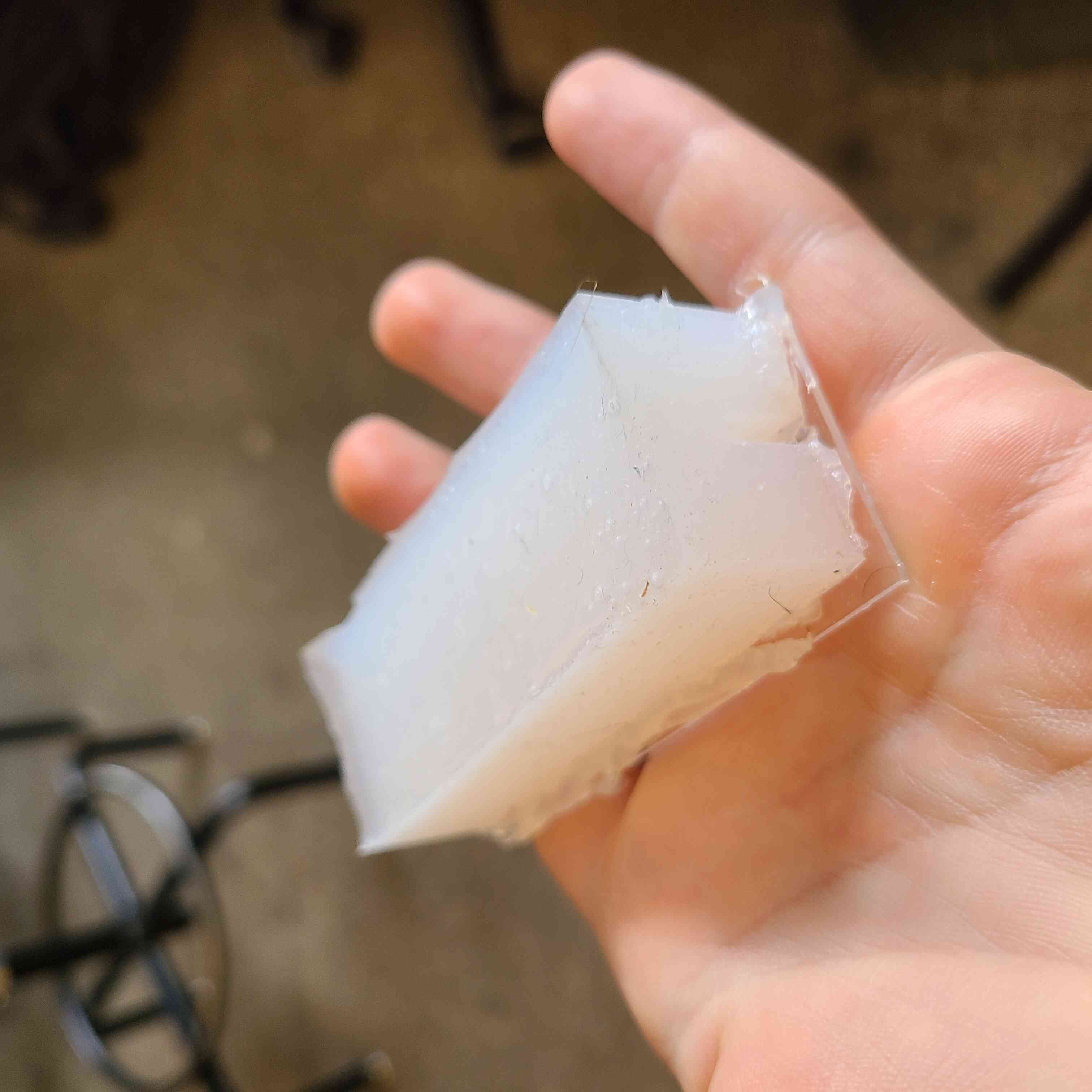
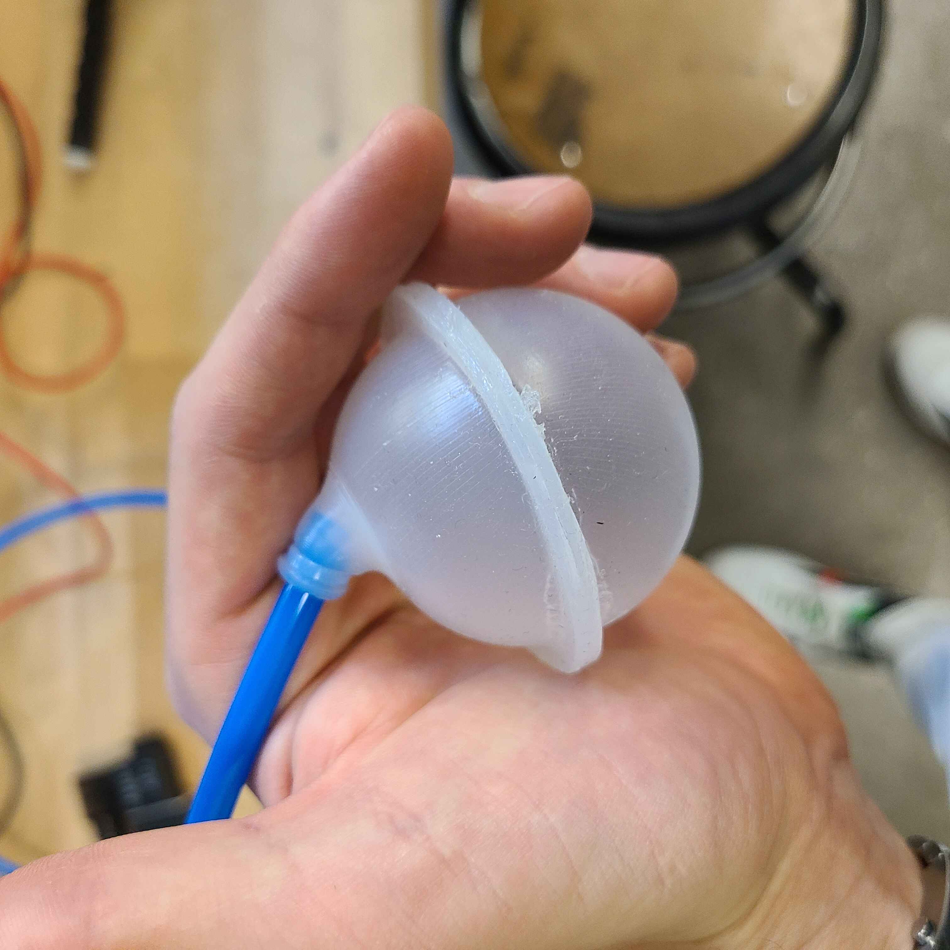
Look at this cute little pillow. It did a stellar job. Now I just need to integrate it into a device and test a bunch more tubing. So let's do the tubing first:
150cm length at 70PSI.
100cm at 70PSI
50CM at 70PSI. As you can see the length of tubing matters a lot. That's because whatever the pressure migt be before the solenoid, if the delivery tubing is twice as long it'll need twice as much air to get to the same pressure. It'll be very important that the length of tubing pre-solenoid and post-solenoi is accurately calibrated.
Anywhooooo, two more pictures and I'm done.
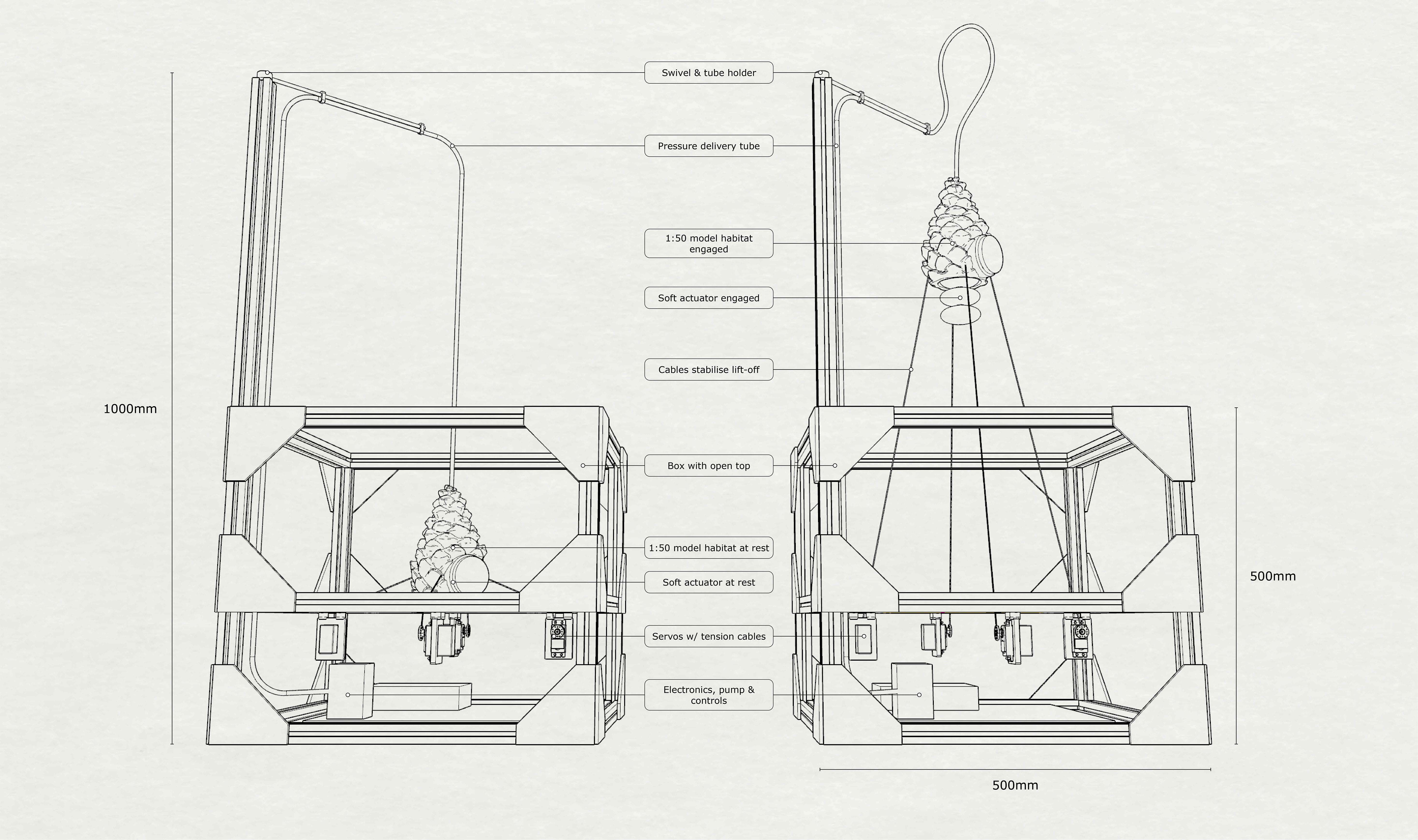
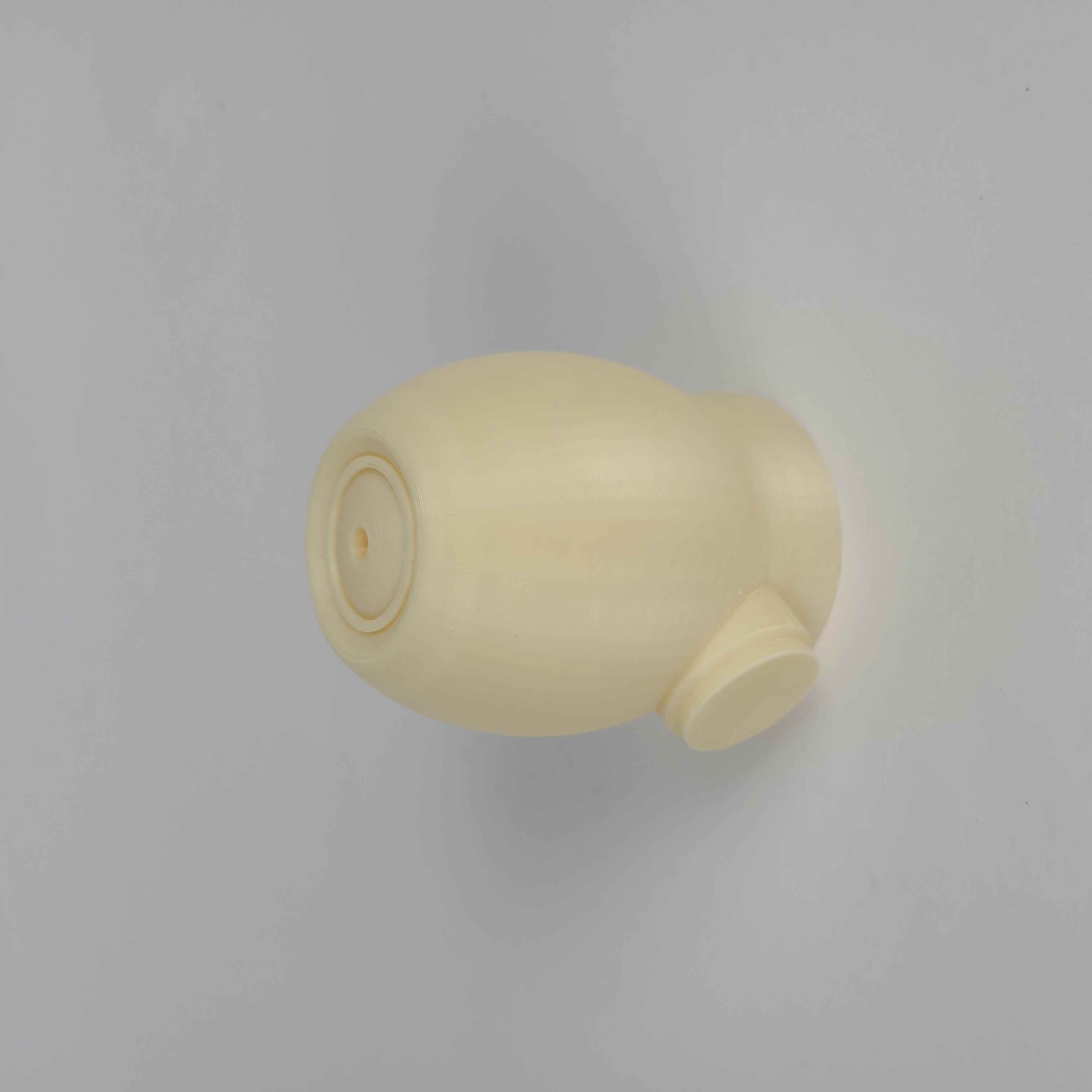
First my 1:100 scale lunar habitat. It has a hole in its head so that I can fit the tubing through there. And then is my integrated package. It's a prototype of a prototype so it's a bit rough around the edges (literally! I got a splinter by handling it with a bit too much affection). What's best though is that it works like intended. I'll be showcasing its magick tomorrow at the final review and so I might upload some videos of the lift-off afterwards. We'll see. Alright bye!
Ok, not quite bye yet. Here's a 1 minute video of my thing working:
I don't know why but I can't get the audio to work in html so you'll just have to imagine the hissing, popping and whirring!