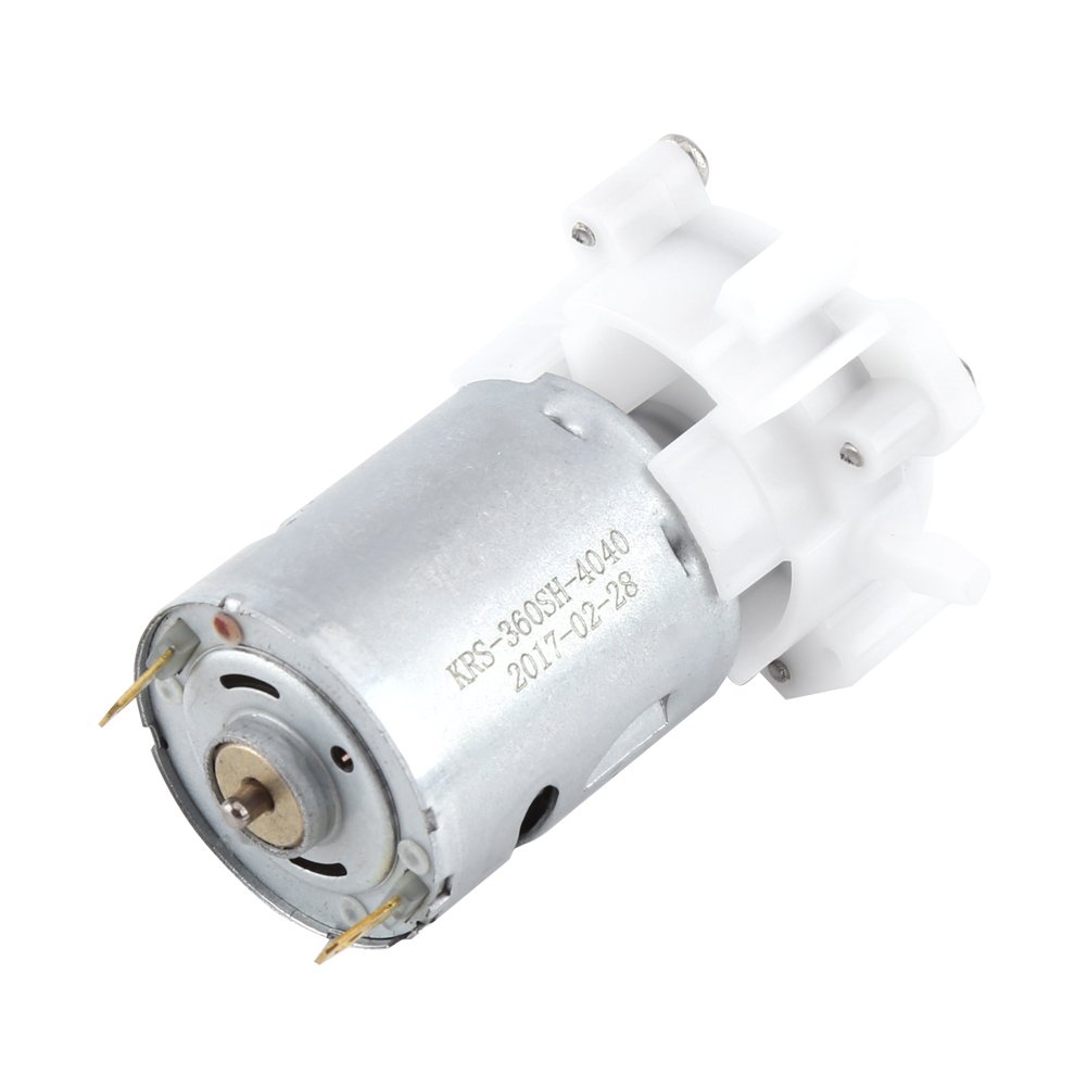
This week I want to try and make a circuit that could power an air pump with a press of a button. The pump is a small 12V aquarium pump (model KRS-260SH-4040). The input voltage can be anything between 3V and 12V but a 5V 2A power supply is recommended (computer USB). The pump looks like this:
I want to try using the SAMD21E microcontroller due the larger number of available pins. I don’t know if this is the correct way to go about this, but I have a hunch I’ll want those pins in the future. Also, I might learn some more in the process. Maybe I should use the ATtiny44 – it seems Neil uses it for his brushed motor examples…
Back to the motor for a bit, I think it may be a BDC Motor (yes, it is a BCD - a Mabuchi Carbon-brush Motor. I also read somewhere that it might be necessary to implement a capacitor next to the motor since its free draw is around 1.72A where its peak draw at the beginning is 3A. I guess I will be compensating for the 1.28A…?
So I was also just looking at Ordering Information on the Atmel SAMD Family specsheet. A student from 2019, Cameron Blackburn decided to learn exactly what each part of the code meant so I got inspired to do the same…
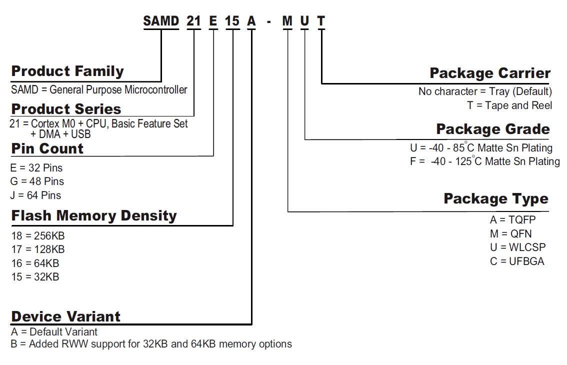
The SAMD21E on the fablab library is show as Microcontroller_ATSAMD21E17A-AUT, which must mean something along the lines of:
AT -
SAMD - General Purpose Microcontroller family
21 - is the product series and Cortex m0 means that it has a small silicone area (what???) and requires low power and minimal code footprint
E - means I get 32 pins
17 - 128KB of memory
A - The variant of the device. Mine is standard. I don’t know what the other one does
A - Package Type, from Cameron I learnt that this literally means what is the packaging on the MC. This one is the quad flat package, which is an SMD (surface-mounted device) with bent, “gull wing” leads extending from each of the four sides
U - Package grade tells you the thermal resistance
T - is just how they’re packed. This one comes in a reel that you pop out like a pill
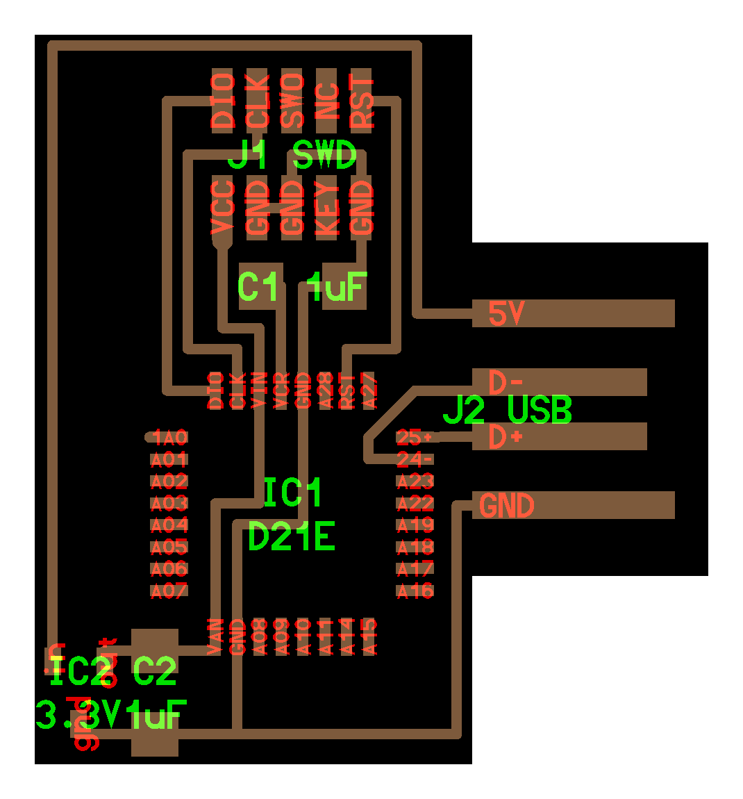
Now, about the PCB I need to make. I was looking at two board examples that might be of assistance to me. First the hello.H-Bridge.44 from the Output Devices week. This one uses an ATtiny44 MC, but I hope I can use the same connection logic in the SAMD21E like in the example hello.D21E.echo from the Embedded Programming week.
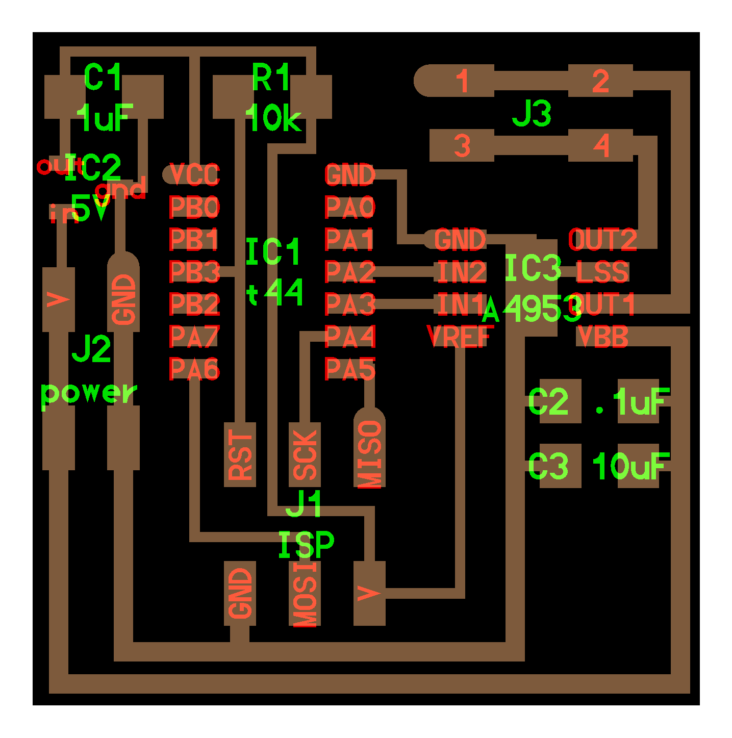
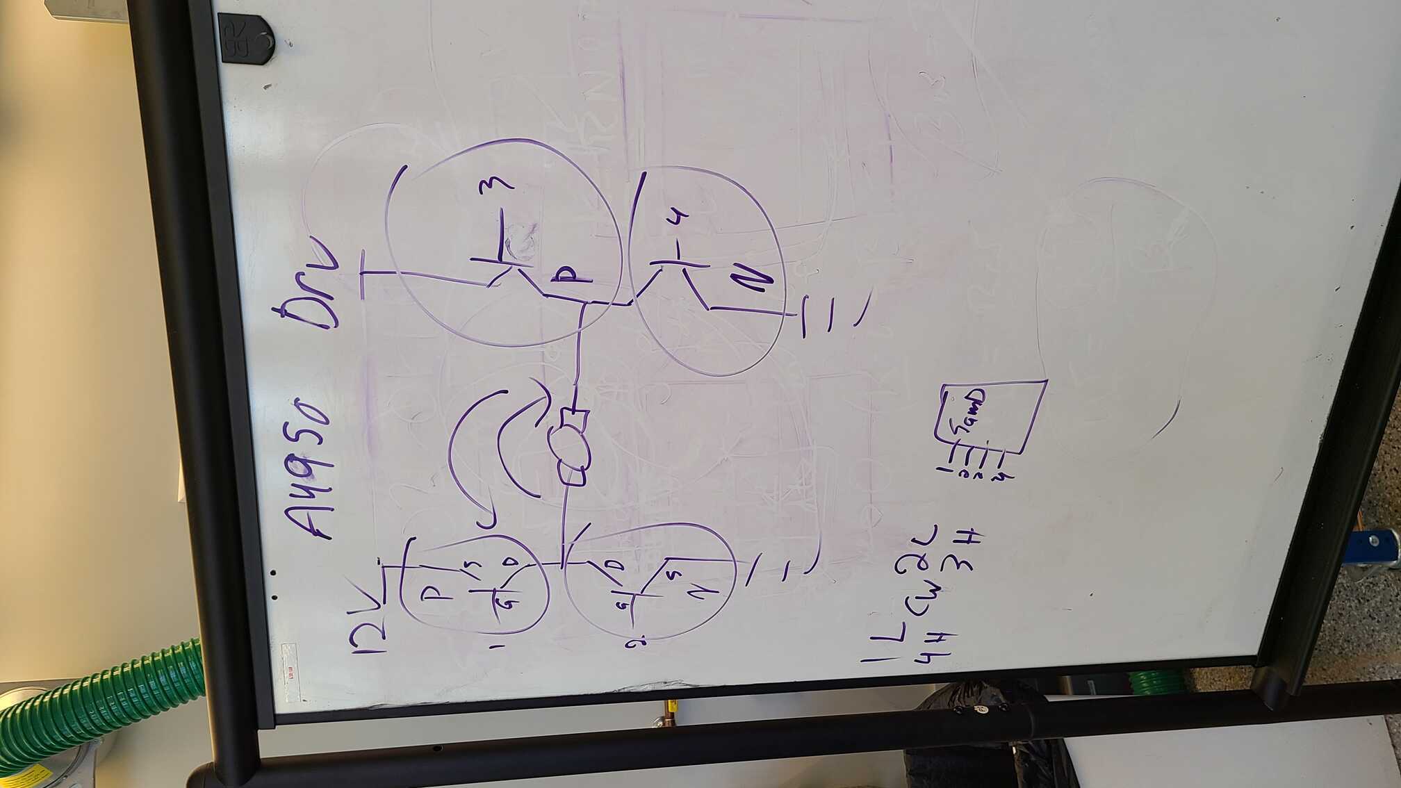
I went to the EECS workshop to get some help figuring out the marriage of the above two boards. I received a good explanation of how MOSFETs work and how they are applied in an H-bridge to get the motor to spin clockwise and anticlockwise. Basically, you have two P-MOSFETs closer to your power source and two N-MOSFETs closer to your gnd. P-MOSFETs are ON when its gate (what connects to a pin on a microcontroller) is LOW – ie there’s no voltage. It is OFF when the gate is HIGH. N-MOSFETs are the opposite; ON when HIGH and OFF when LOW. On your MC you then have four pins that individually control the 4 MOSFET gates with the intent that current flows from the power source, through the top-left P-MOSFET, through the motor (spinning it clockwise) and then through the bottom-right N-MOSFET and off to gnd. If you want to spin the motor counter clockwise you go power source > top-right P-fet > motor > bottom-left N-fet > gnd.
During the Office Hour I also spoke about sizing correct voltage regulators (100mA not 1A), more convenient header pins (2.54mm not 1.27mm), some general schematic-drawing trivia and, most importantly, getting the correct motor for the job – ie. making an inflatable building which you can control. Apparently the pump I have shown above is totally not going to cut it and I need a peristaltic pump, which are often used in medical and pharma solutions. It looks like this:
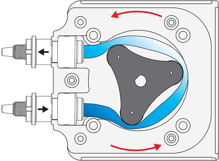
Instead of having blades (like what my pump probably has) and allowing the air to escape after the pump has been turned off, this one has a rotating constrictor that both pushes air one way or the other, but also doesn’t allow it to escape after it has been turned off. I’ll have to order one to test it out, but it looks promising. I nevertheless am going ahead with the same set up for my PCB since a small peristaltic pump will also run on a 12V BDC motor.
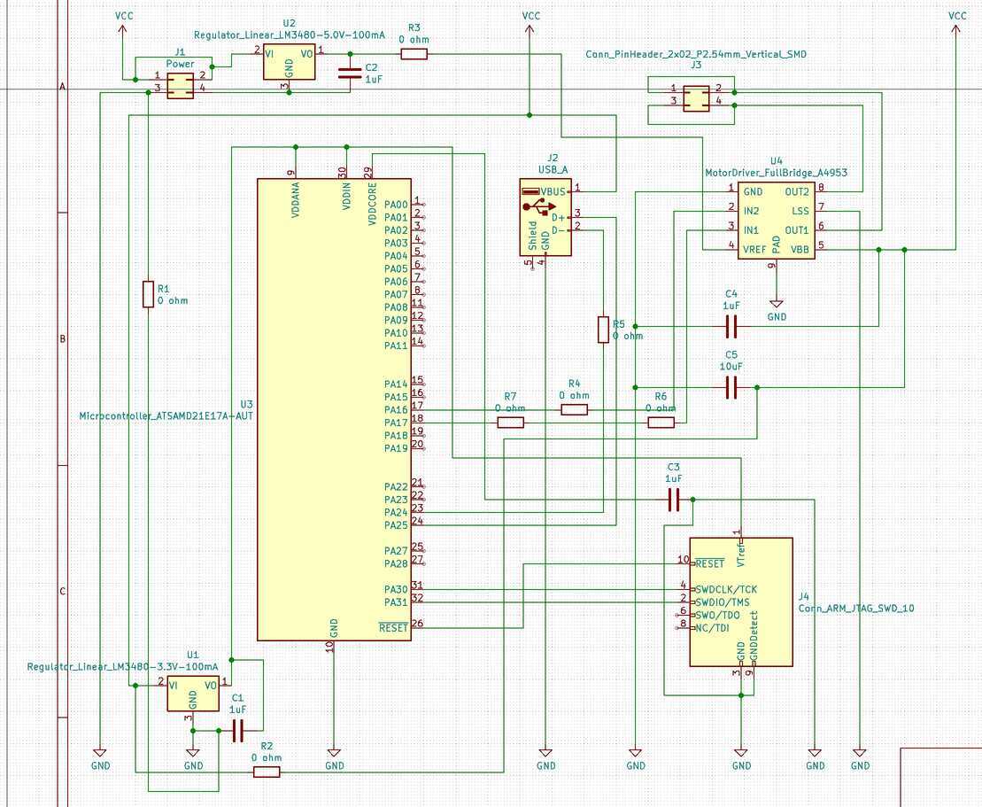
So I applied what I learnt to my KiCAD schematic. With my new understanding the process went a little smoother (though not silky smooth) and I was able to pick and place components with more confidence. I did run into the problem of picking the JTAG SWD 2x5 pin header because it wasn’t in the fab.lib folder, but a quick cry for help on archsite resolved the issue.
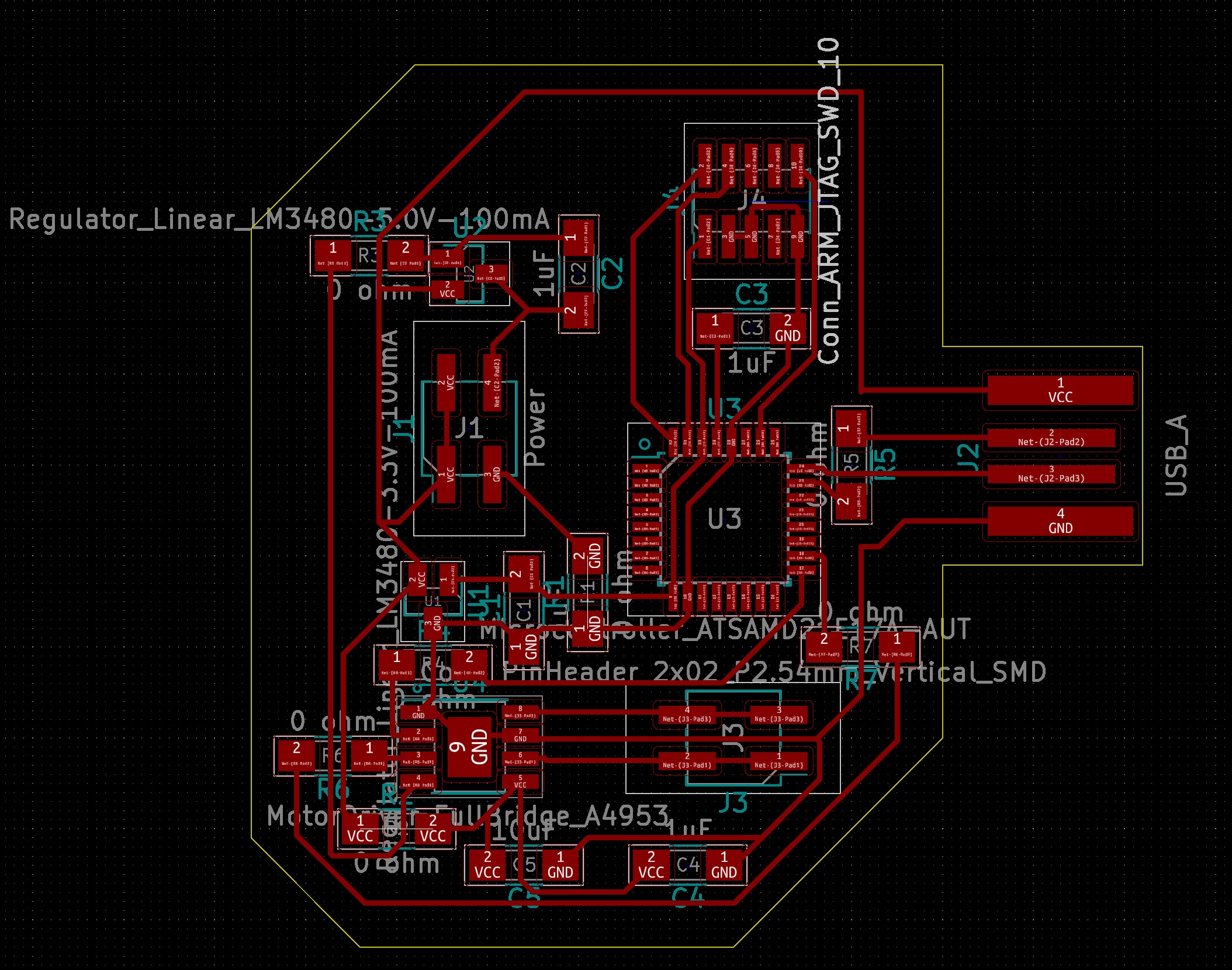
And here is the board view of my PCB. A bit messy on the traces, but it seems to do the job. It’s worth noting (and you’ll see why in a bit) that I had to reduce the clearance and trace width properties in the Board Setup from 0.5mm to 0.3mm because the SAMD21E has such tight spacing between its pads that KiCAD refused to draw my wires. And now to the failure…
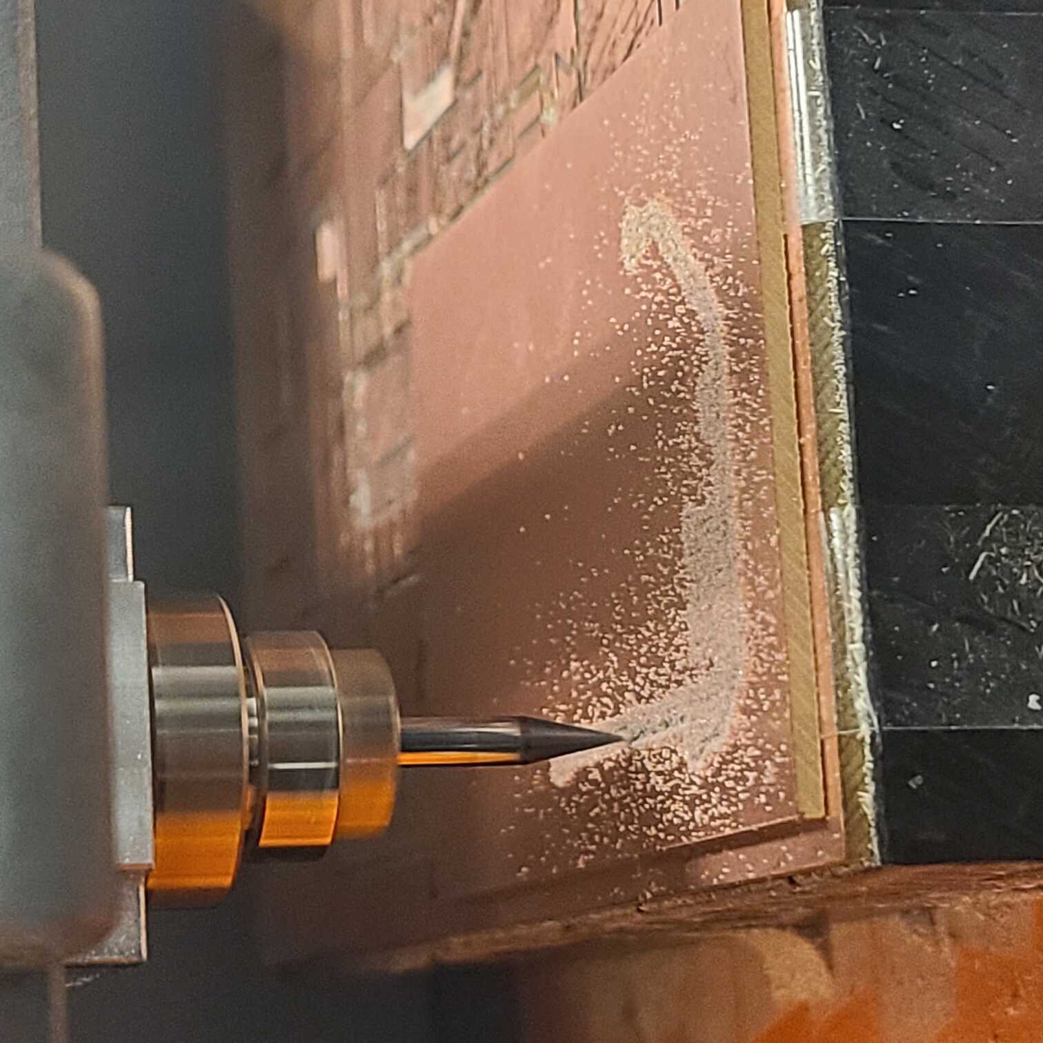
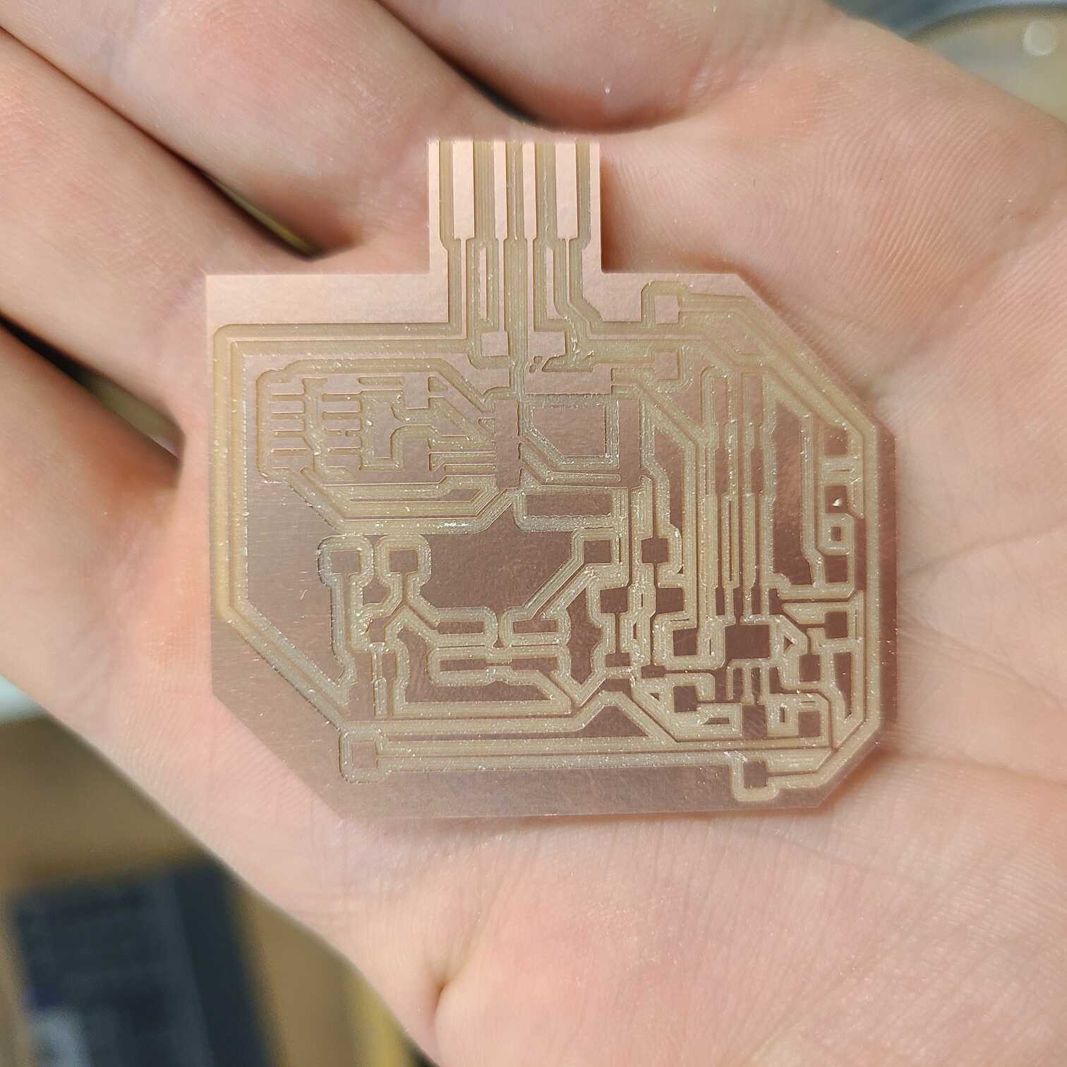
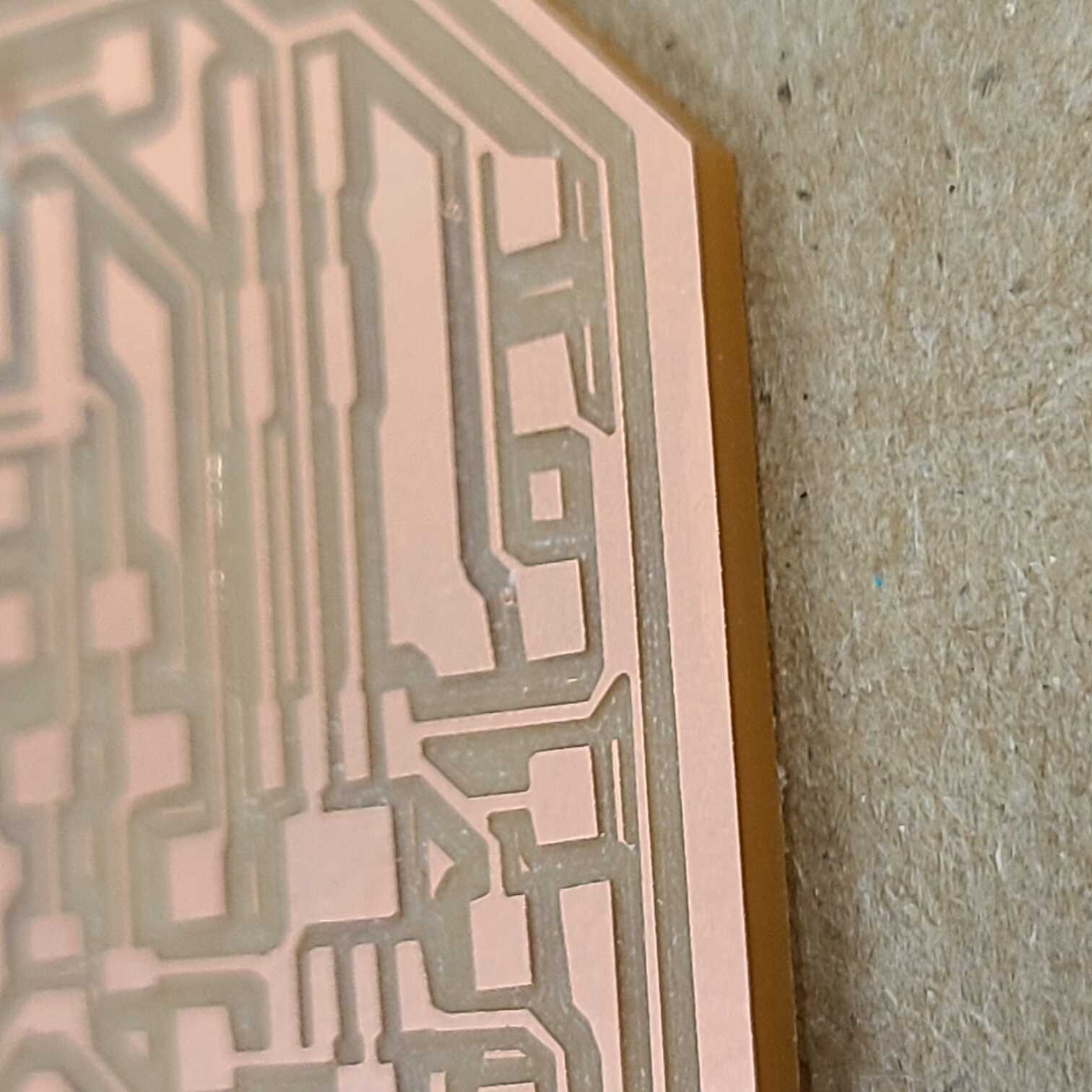
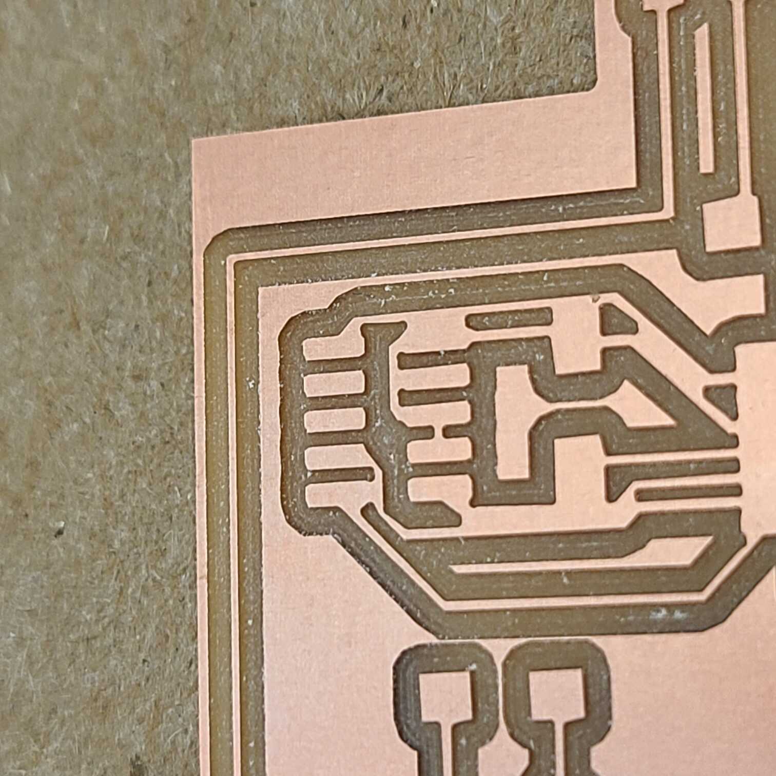
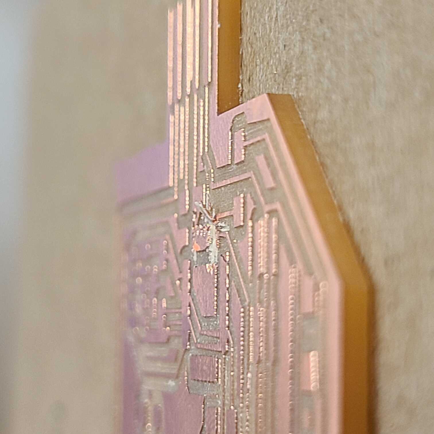
was looking fine, the mill did some cutting, I did some vacuuming and viola, a board. But then I looked a bit closer and I saw that some of my traces came out connected to adjacent ones. So did my SAMD21E pads. Calvin told me that this was something that happens on mills with 1/64in bits so I guess I just ran out of fidelity. Anyway, I tried sculpting away the excess with a knife, but second pad in I ejected a vital piece of copper off the board making my entire PCB basically garbage.
As I’m writing this it’s Tuesday evening and you know what that means; no new PCB for Alek before Wednesday’s class. Let’s hope I don’t get randomly selected to present my work lol.