Initial Design
The Pleisiosaur robot can be broken down into key components:
Power Supply - wall power
Actuators - this robot is tendon actuated. Fishing lines are used to convert energy into movement
Electric Motors - DC servo motors provide rotational movement
Controller - D11C microprocessor connects computer input to servo output
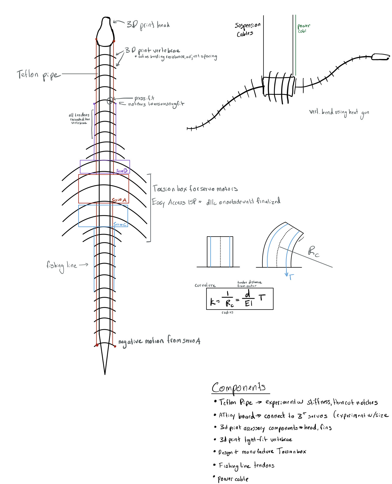
Body/Frame - 3D printed skeleton mounted on a flexible teflon tube
The next step in the design process was sketching out my frame, performing some brief calculations, and planning out the robot's motion.
3D modelling in Fusion
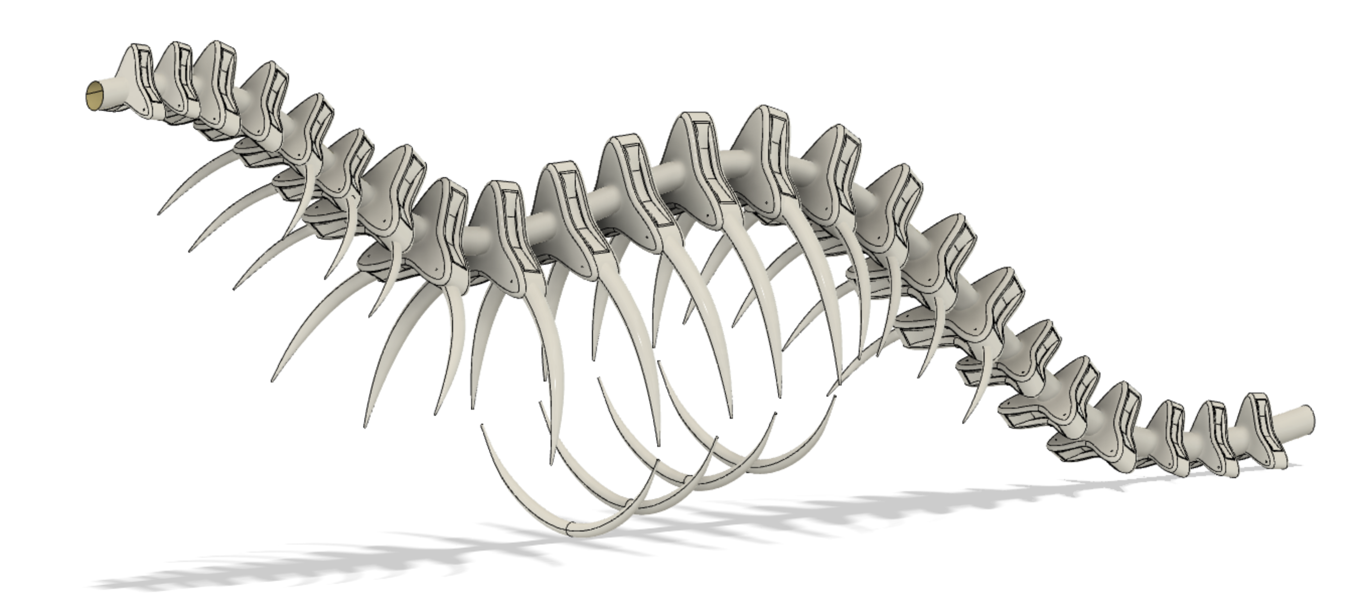
My CAD model has quite a lot of parts (113 bodies and 119 sketches), so I'm going to walk though my process step by step.
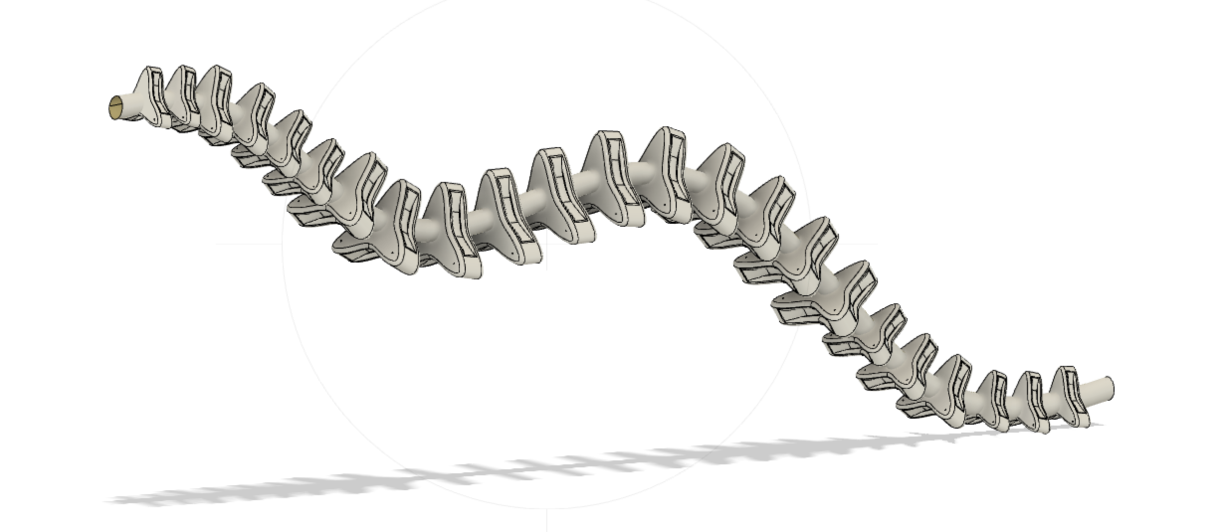
Spine: Starting off with a sweep, I used a circular profile and handdrawn curve on a perpendicular plane to model the spine (later to be teflon cable of diameter .36 in).

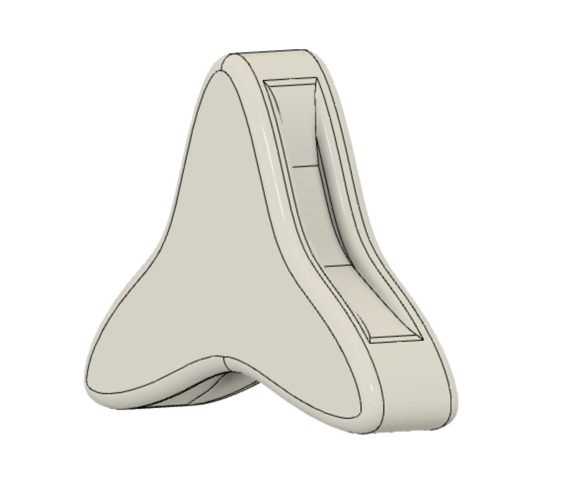
Vertebrae: Next, I modelled my a vertebrae using a series of parallel ofset planes, the extrude function, and the fillet function.
The pattern along path command can be used to create a series of vertebrae, oriented in the path direction. The scale feature was used to create incrementally smaller vertebrae towards the ends of the spine. I used the extrude command on cut mode to add symmetrical holes for the fishing line tendons.
Ribs: Once again using the sweep function, this time I created an oblong profile and a curved guiderail to mimic the natural tapering of ribs. Next, I used pattern on path and the mirror commands to create the full set of ribs.
The ribs wrapping around the motor box have the same orientation for structural integrity and to prevent overlap, while the ribs along the neck and tail are scaled down incrementally and oriented along the path direction.
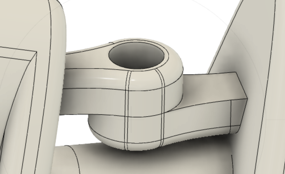
Joints: The teflon spine is flexible, so a series of joints is needed to restrict 5 degrees of freedom, leaving only 1 rotation direction. The push-in rivets I ordered have the following dimensions: 0.145 in Dia., 0.395 in L, 0.115 in.
My joints have a height of .24 in to accomodate the .25 grip range, and a diameter of .15. To create a series of joints, I once again used pattern on path, this time using a shortened joint as my original and split body to create two halves.
Next, I used extrude to object to fuse each joint to it's adjactent vertebrae. This accomodates a range of vertebrae angles. Lastly, I used the combine function to make each vertebrae+ rib (x2) + joint (x2) set a solid body for 3D printing.


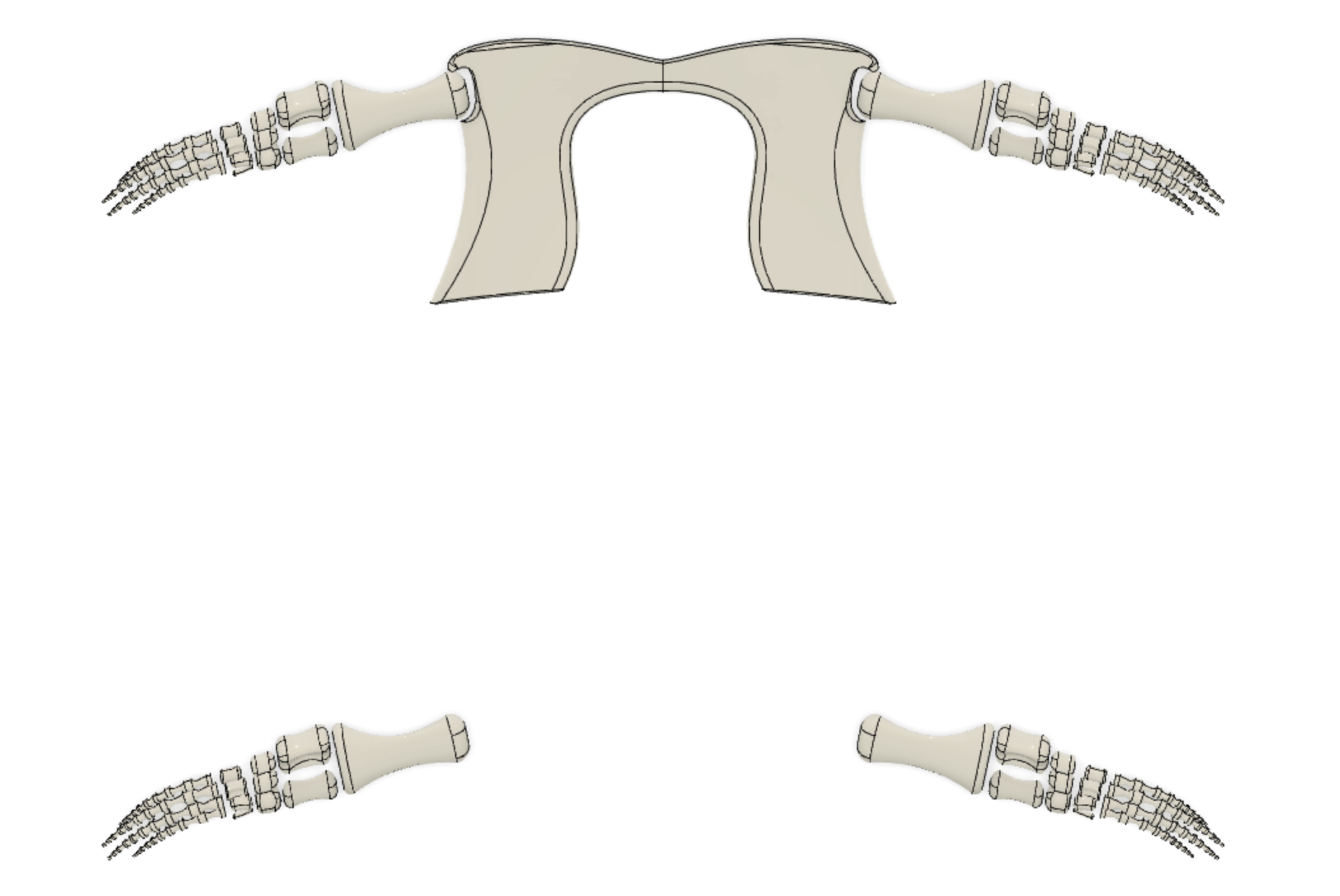
Fingers/limbs: for the fingers, I used the sweep with guiderail function. The limbs were a series of extrudes, with a very liberal use of the fillet function to create a more organic shape.
Once again, the mirror function saved me a lot of time.