Week 2
Electronics Production
Tools: Autodesk Eagle | Adobe Photoshop | Modela PCB | Soldering Iron
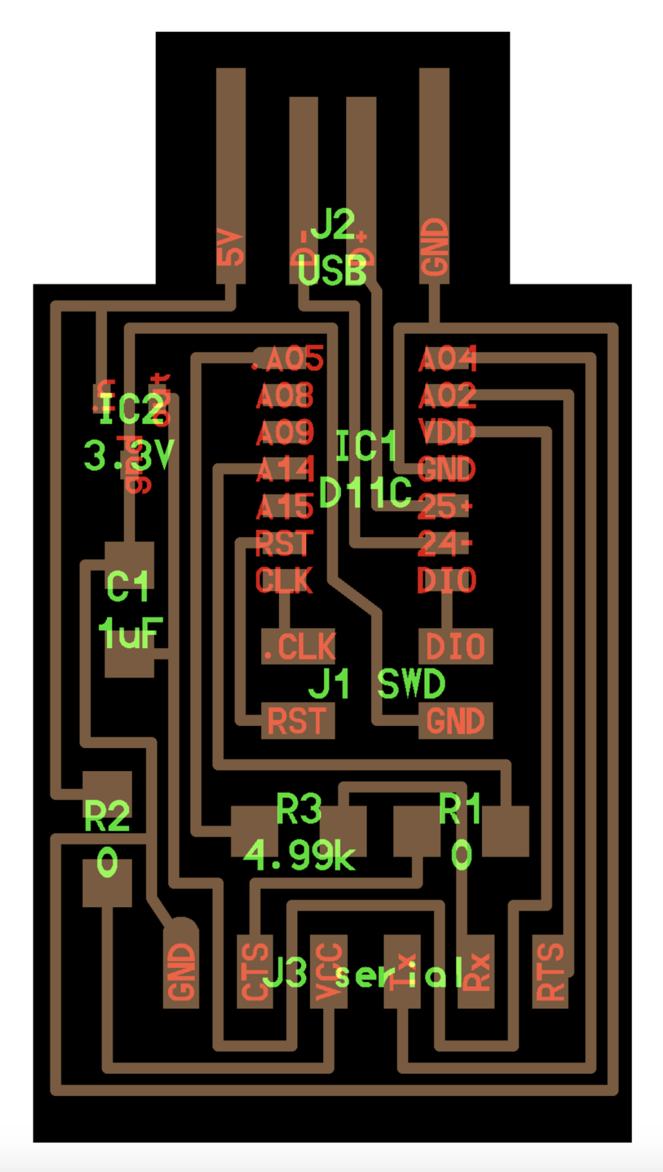
Materials: Solder | Copper Printed Circuit Board | D11C | 6x1 Serial Header | 1 uF Capacitor | 3.3 Voltage Regulator | 2x2 SMD Header | 0k/5k Resistor
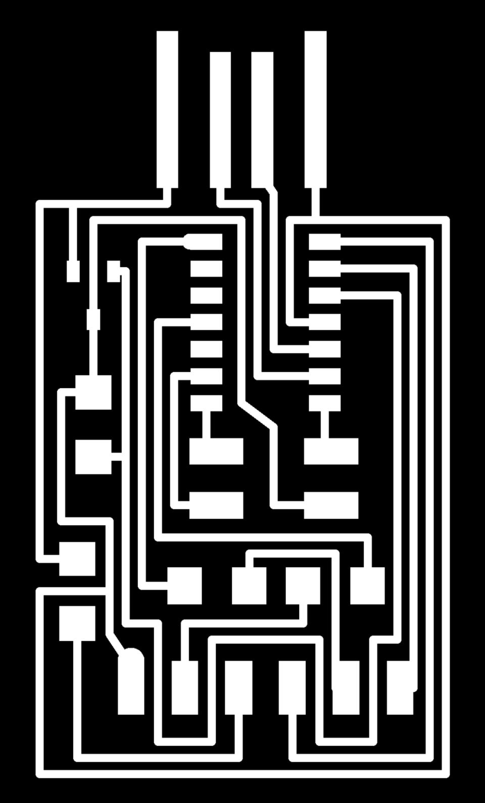
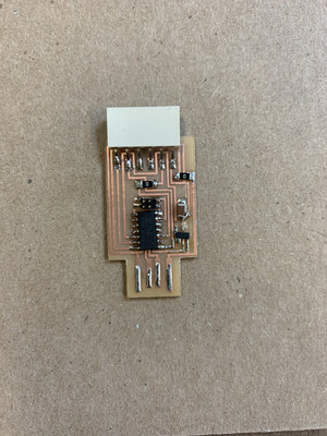
This week I made and tested a D11C serial converter using a PCB endmill.
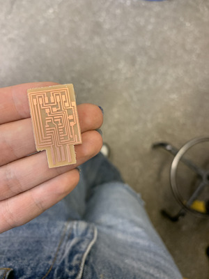
Milling Process: to set up the machine, I selected a medium-sized scrap piece of copper and attached it to the milling area using a piece of double-sided tape. Next, I chose a origin at the bottom left corner of the copper plate to minimize wasted material. After screwing in a 1/64th diameter end mill, gently lowering the mill, and retightening the screw, I was ready to prepare the computer file. The next step was uploading Neil’s PNG, calculating the file, and sending it to the computer. To mill the outline, I replaced the screw with a 1/32th diameter mill and recalculated the file without adjusting the origin. I milled Neil's hello.D11C.serial board
Learnig Process: having a set training time with Jennifer turned out to be a much more fluid process than figuring it out on my own. The first milling mistake I made was switching to a 1/32-point tip without adjusting the computer settings. This is an easy fix, I switched to the appropriate setting and milled again without changing the copper’s position.
The second milling mistake I made was cleaning off scraps and dust with the vacuum without removing the milled board. The milled board got sucked into vacuum. Luckily, no damage was taken as the board fell out after I shook the vacuum tube.
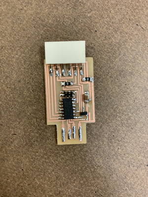
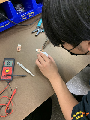
Soldering: I have had past soldering experience, but never on such a small scale. A technique that helped me transition to a smaller board was placing down a small ball of solder first, melting the solder as I place the part on the board, then adding solder on top of the board to secure it.
After soldering the board, I tested the points using a multimeter looking for a beep indicating there is a voltage drop where 2 points shouldn’t be connected and vice versa. The majority of my solder joints worked, but I had placed IC2 in the incorrect location. It took a few tries to learn how to remove solder, but it clicked when a TA explained the mechanism. I successfully removed the solder and tried again.

For another example of PCB fabrication, click here