Week 4
Electronics Design
Tools: Autodesk Eagle | Adobe Photoshop | Modela PCB | Soldering Iron
Materials: Solder | Copper Printed Circuit Board | ATtiny 44 | 3x2 Header | 10 uF Capacitor | 5V Voltage Regulator | 20 mhz Resonator | 2x2 Header | 3x2 SMD Header | 10k Resistor
Assignment: Redraw an echo hello world board. Add (at least) a button and LED (with current limiting resistor). Check the design rules,
make it, and test that it can communicate.
PCB Design in Eagle
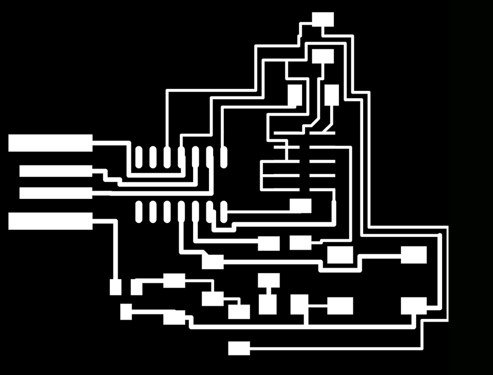
Board Design: I picked the D11C echo 10-pin board to recreate in Eagle. It was my first time with the software, so the Eagle
tutorial proved invaluable. Initially, I had problems loading the FAB design rules and library, but I found that changing the
path the Autodesk Libraries folder fixed the issue. My second issue was the inability to select nets and wires. Resetting the selection
filter on the right side of the schematic helped.
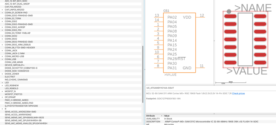
Parts Used - in FAB library notation
IC1 D11C: UC_ATSAMD11D14A-SSUT
J1 SWD: CONN_O5X2_ARM_DEBUGSMD
J2 USB: CONN_USBPCB
IC2 3.3V: VR_REGULATOR_SOT23SOT23
C1 1uF: CAP_UNPOLARIZEDFAB
Switch: SW_SWITCH_TACTILE_6MM6MM_SWITCH
LED: LEDFAB1206
Resistor: R1206FAB
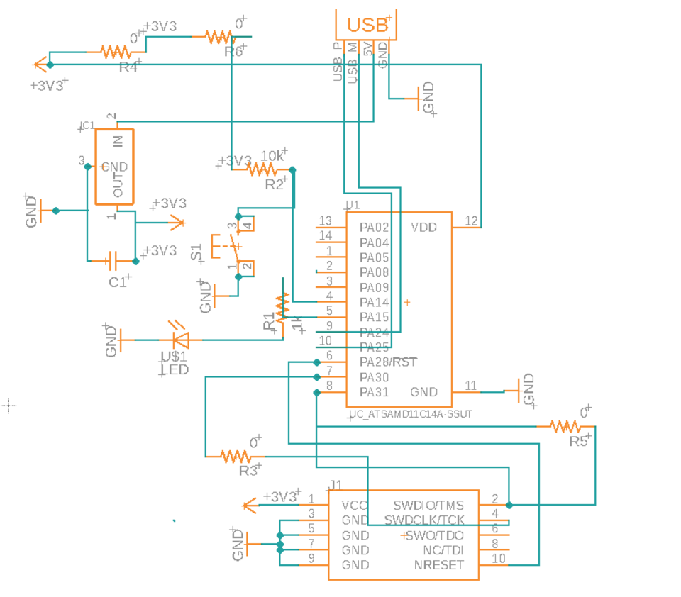
After replicating the D11C echo, I added a reset switch to the board. By wiring pin 2 on S2 to ground, when the button is
pressed, the voltage drops from HIGH to LOW, turning the board off. Pins 2 and 4 were easily available, so I wired an LED
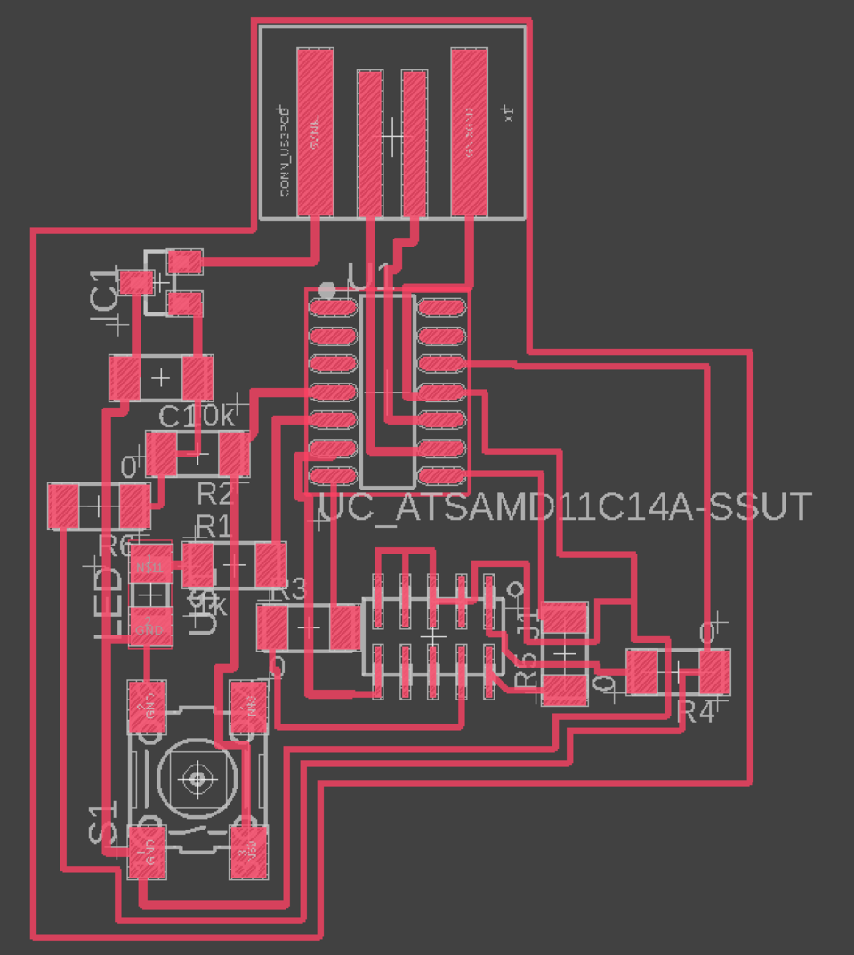
with a current-limiting resistor on Pin 4. On pin 2, I added a switch and pull-up resistor. I really enjoyed routing the
wire on the PCB board. The most helpful rerouting tip was adding 0-ohm resistors at intersections between crossed wires
(0 ohm resistors have a negligible influence on the current).
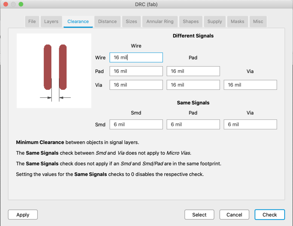
Before exporting, I checked the design rules using the FAB design rules .dru file.
The last steps were:
1) Outlining the PCB with a rectangle using the Polygon command on the 20th dimension
2) Outlining the PCB with a line of width “0” using the Line command,
3) Deleting the dark grey grid outside of the polygon
4) Exporting the traces. This can be done by using these commands: display none, display top pads vias, export image (selecting monochrome and 1000 dpi to export a high quality b/w PNG
5) Exporting the outline. Use commands: display none, display bottom vias dimension, export image (monochrome, same 1000 dpi).
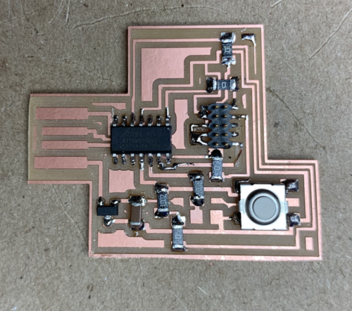
Finished Product
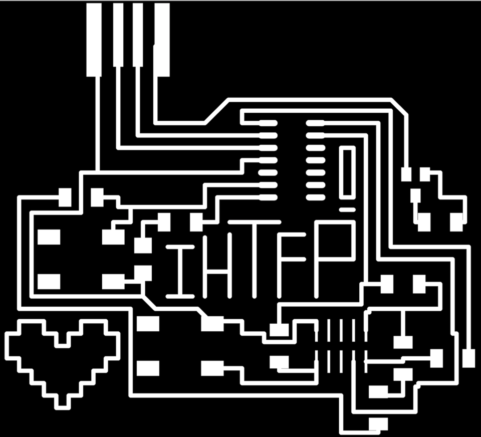
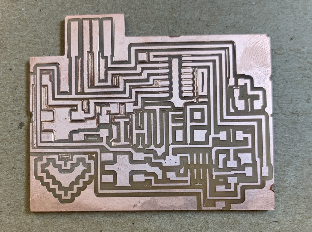
Honorary Mention
My IHTFP board - my 1st attempt at board design.
Milling
My milling process was delayed due to 3 problems. Firstly, Eagle has a bug where the exported image is scaled by 2 on MacBooks with retina displays.
A quick solution to the problem is doubling the dpi on mods.
The Roland SRM-20 had something stuck in the component where the endmill is inserted.
Immediately, there was a loud grinding noise when I began milling. I cancelled the job, turned off the machine, and asked the shop manager for tech support.
The modela MDX-20 simultaneously had an error where the endbit origin was
located at the right hand side of the board, not leaving enough mill space for the copper. Luckily, I found out that these errors were both due to debris/gunk stuck in the machinery
from pervious students.
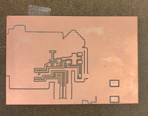
My second milling attempt was more sucessful. The process was smooth, but there were certain portions of the coppper that should have been milled but weren't. I'm still investigating the root cause of this problem.
When exporting the images, they weren't automatically cropped, instead the design was floating in the bottom left hand corner. I cropped the images by hand, which isn't very precise. In the final product, the USB had
extra space and the leftmost resistor was (almost) cut off.
As shown below, there are certain copper sections that should've been milled but weren't. My board passed the design rules in Eagle, so I'm not sure where this problem came from.
Soldering was a much more streamlined process now that it was my 2nd project soldering on such a small scale. Finding the components was also easier because I could reference
traces and part numbers in the FAB library I imported into Eagle.
When I asked Calvin why he wasn't working, he launched into a very long list of blaring errors (not all my grounds were wired together, my VCC's were inconsistent), meaning I would have to do a lot of rewiring.
I opted to start from scratch, and didn't have the time to fit my IHTFP text and heart into my final functioning board.
For another example of PCB fabrication, click here