Week 6
Embedded programming
Fixing Week 4's PCB
Re-milling: pictured below is last week's board. I had several bugs to fix that I didn't have the time to address last week.
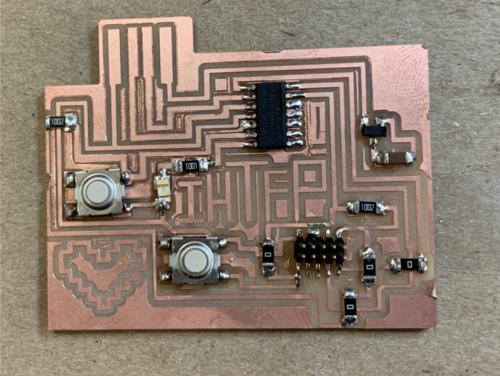
As you can see, the traces on the left hand side got cut off and there was unnecessary copper at the top of the usb.
The trace borders have a thin outline, and some traces are conjoined. Several spots that should have been milled were left untouched,
for example the blocks inbetween my center text 'IHTFP'. I've summarized the bugs below.
1) Exporting the border - outline too thin.
2) Cropping the border - png wasn't centered.
3) Unwanted joined traces.
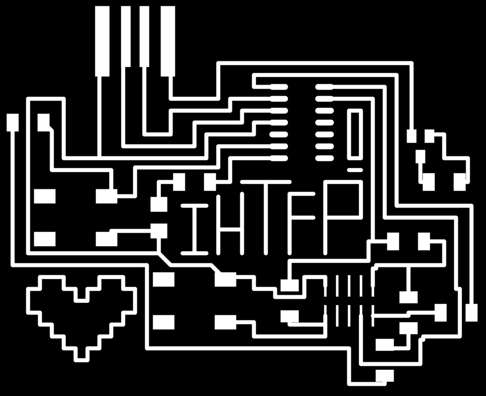
Jennifer gave me very helpful advice regarding the first two problems. I drew a ground line where my border should have been, exported only one image (
display none, display top vias pads) and duplicated it. Then I duplicated it and manuallly manipulated the image in photoshop.
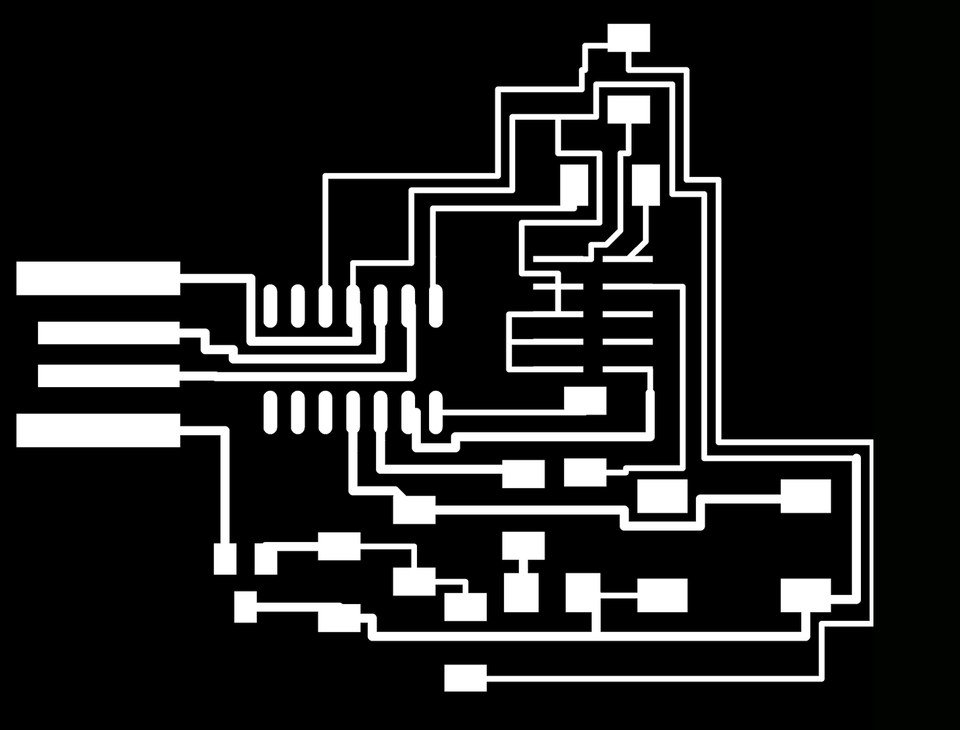
For the joined traces, I simply separated them with an exacto knife. Here are my updated traces:

After sucessfully milling and stuffing my board, I gave it to a TA to check. A more detailed check showed that my +3V3 traces weren't properly connected, my
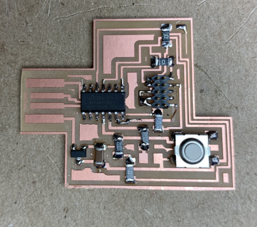
reset button was redundant and took up too much space, and my capacitor wasn't wired to ground. Huge shoutout to Calvin, who helped my organize my traces and frequently checked my work.
I would not have been able to finish my board in time without him. Sadly, in the interest of time, I had to leave out the text and heart on my board. Here is my final product:
Programming
Before uploading code to your board, it is important to program it using a bootloader. A bootloader essentially tells the board what it's function is.
After connected my board to the 3-402 computer using a JTAG programmer,
edbg was used with the following command: ./edbg -b -t samd11 -pv -f sam_ba_Generic_D11C14A_SAMD11c14A.bin . Now, I can re-program my board through a serial port using the Arduino IDE.
Arduino doesn't automatically support my D11C board, so I loaded https://raw.githubusercontent.com/qbolsee/ArduinoCore-fab-sam/master/json/package_Fab_SAM_index.json into my board manager and added Fab SAM core for Arduino.
To check if the previous steps were completter sucessfully, I made sure the board appeared in the 'port' menu. Now, the board is ready to program!
Arduino
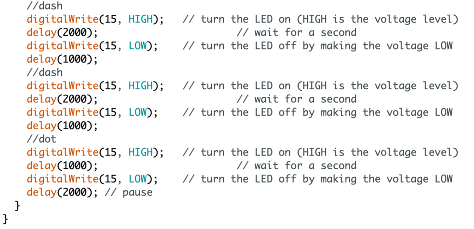
With only a button and an LED, I was limited in what I could upload to the board. When the button is pressed, the LED outputs 'IHTFP' in morse code.
.. .... - ..-. .--.
I have attached snipets of my code below.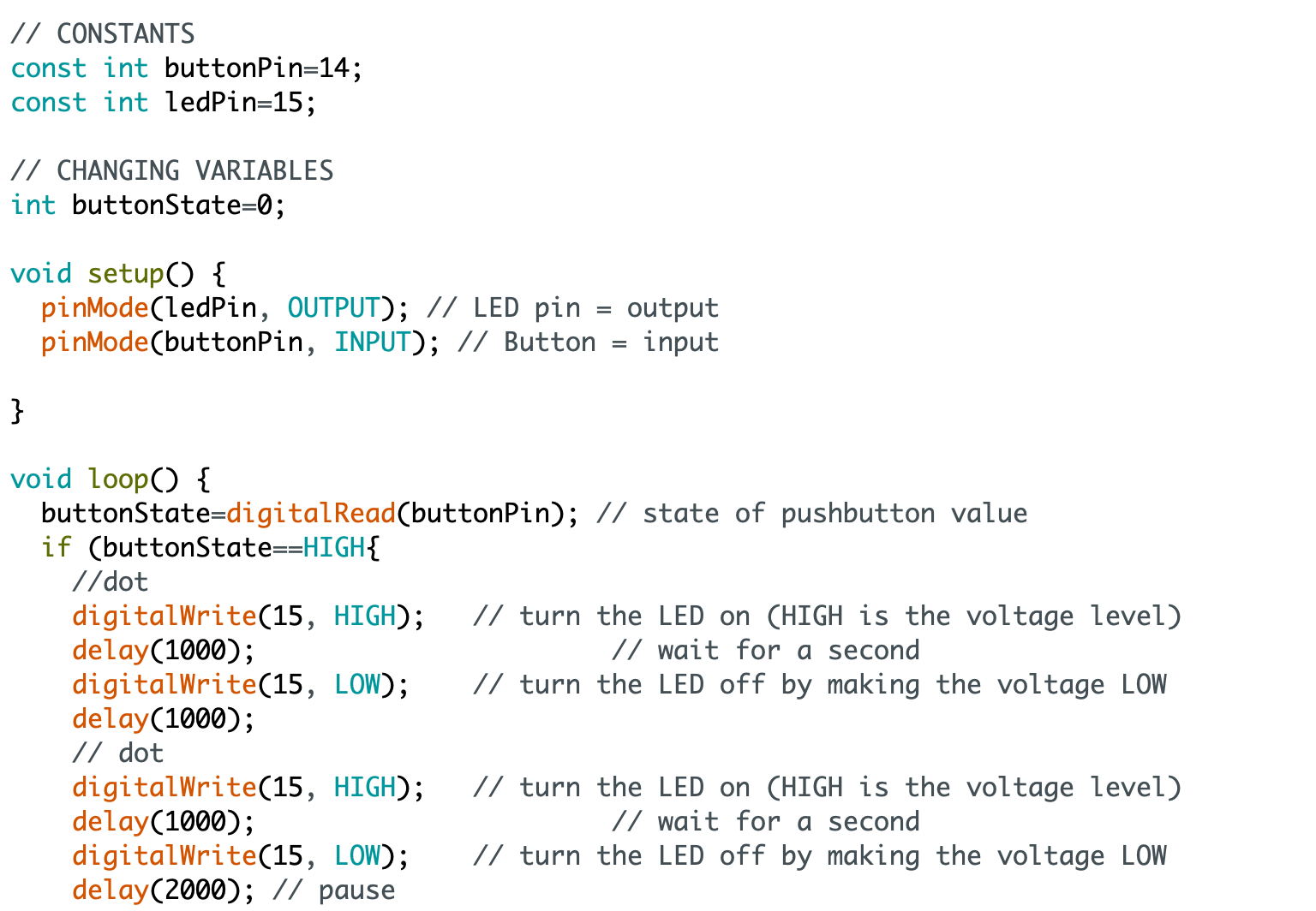
For another example of PCB fabrication and bootloading, click here
For another example of Arduino Code, click here