Input Devices
Microcontroller PCB
Machines used: Roland Modela SRM-20 | Eagle | Python | Vinyl Cutter
Materials used: copper plate | ATtiny45 | CONN_06_FTDI-SMD-HEADER | CONN_03X2_AVRISP | 1 uF capacitor | 1m 10k resistor | copper tape
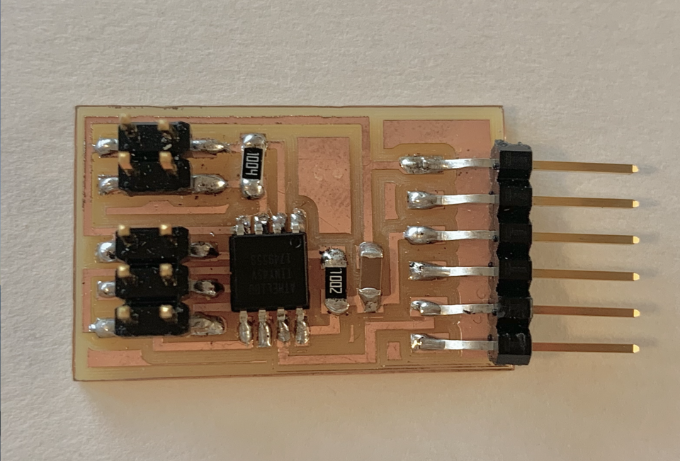
To start this week's assignment, I printed, soldered, and stuffed a hello.txrx.45 board.
This is a loading-only step response board, meaning it depends on room ground for current return and uses one charging resistor.
Programming
The ATtiny45 is an active part, but it still needs to be programmed with an ISP programmer, for example the Atmel ICE in the architecture shop. To load the bootloader, follow these steps:
1) Download hello.txrx.45.c and hello.txrx.45.make and place the files in the same folder.
2) Connect your board to the Atmel ICE through the ATtiny 45. Be sure to line up GND and VCC.
3) Open terminal on your computer, cd into the folder with your files.
4) Run $ make -f hello.load.45.make program-ICE.
5) The board now needs a serial bridge to connect to USB. I could've used the SAMD11C I made in Week 2, but I opted for a cable in the architecture shop.
Step Response
A step response is a sensor used to calculate force, weight, and resistance using 2 sheets of copper, commonly separated by a porous insulating material. Heres how it works:
Tx pin: alternatively high (5V) or low (0V). This charges/discharges the tx electrode.
Rx pin: sends 'blips' as tx pin toggles, which are measured by Arduino analog input (ADC).
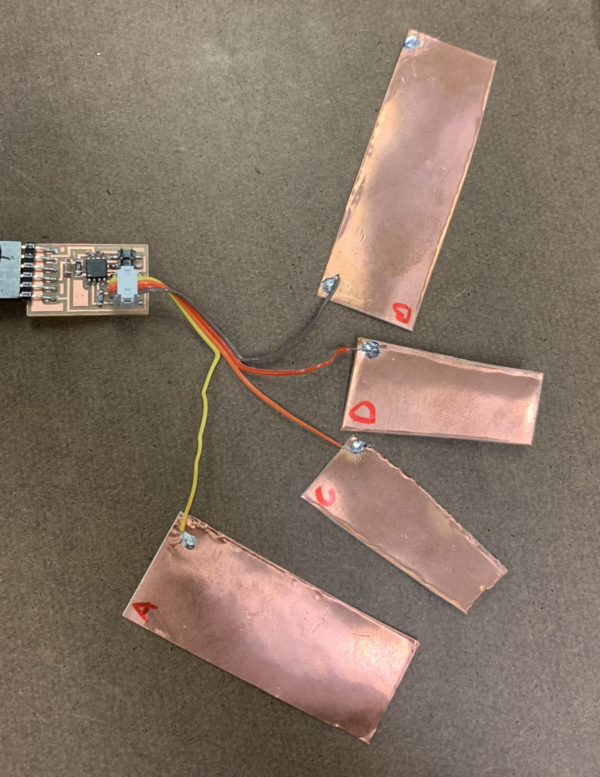
I used the 2 electrodes to work with 3 sheets of copper as the intermediate material. I am interested in exploring the touch sensing capabilities of this circuit, so I performed some simple tests on my 3 copper sheetss using a python program.
Use command program python3 hello.load.45.py /dev/ttyUSB1 to recieve measurements.

Copper plate D exhibited the same behavior as copper plate C, so I excluded redundant data. Here are the results of my simple (unitless) measurements:
Resting: 770 786 1010
Only A: 320 320 600 Only B: resting Only C: 795 810 1010
A+B: 500 500 500 A+C: 1010 1010 1010 B+C: resting
A+B+C: 700 700 700
The next step was picking a direction for the trackpad. My goal was to use the vinyl cutter to create a touchpad that increases in value as you move from left to right.
Below, I plotted the copper pad combinations that resulted in varying values.
Next, I drew a quick visualalization that combined numerical results with copper pad combinations that resulted in a cohesive 'flow' where there are no breaks per copper pad.
The first wave depicts my measurements on the x axis integrated into a rough draft sketch. Similar to the above 'flow', each color-coded copper pad has no breaks or overlaps.
The second wave is a 2nd draft, where I included pads on the perimeter to solder the electrodes to a connector, thickened the traces, and cleaned up any overlaps.
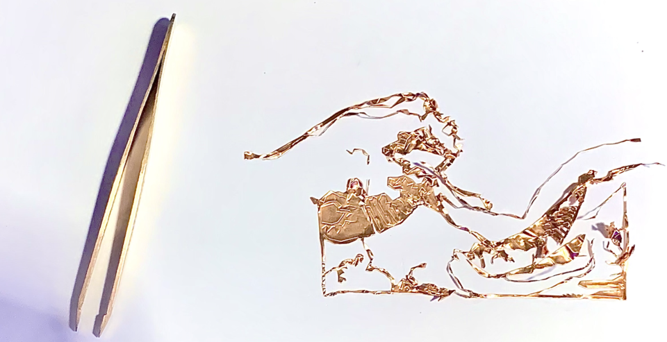
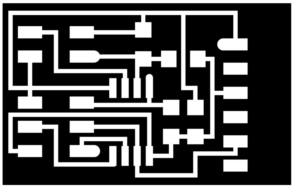
The final b/w wave is the input into the vinyl cutter.

Vinyl Cutting with copper was the biggest challenge with this weeks assignment. Firstly, the terminal link for mods was faulty, I spent many hours with the TA's trying to establish a connect from the computer to the cutter.
Here are the steps that worked. The order is very important.
1) Turn the vinyl cutter on. Load the roll of copper tape, and set the material type to 'roll'. Double check the roll sensor is covered. Set your origin.
2) Unplug USB port from computer, replace with vinyl cutter cord. It will not work if you plug the vinyl cutter cord into the USB connector directly.
3) Open up terminal, cd into mods/js.
4) Run $ node deviceserver.js ::ffff:127.0.0.1 1234. The prompt should say "listening for connection from client address ::ffff:127.0.0.1 on server port 1234"
5) Double click the mods shortcut on the desktop. Select "open socket". The terminal window should now display "connection accepted"
The next step was playing with the speed/power settings to adjust to the copper tape. To little power will result in a score not a cut, and too much power will mangle the copper tape as it is very delicate.
The material was very expensive, so I had to be careful with the amount of testing I conducted. The ideal middle ground was speed 2 power 75.
Tragically, the last step in the process was too difficult for me to troubleshoot. After sucessfully printing the copper, I did not know a method to transfer the delicate, cut tape to a surface.