Week 9
Output Devices
Tools: Autodesk Eagle | Adobe Photoshop | Modela PCB | Soldering Iron
Materials: Solder | Copper Printed Circuit Board | ATtiny 44 | 3x2 Header | 10 uF Capacitor | 5V Voltage Regulator | 20 mhz Resonator | 2x2 Header | 3x2 SMD Header | 10k Resistor
PCB Design in Eagle
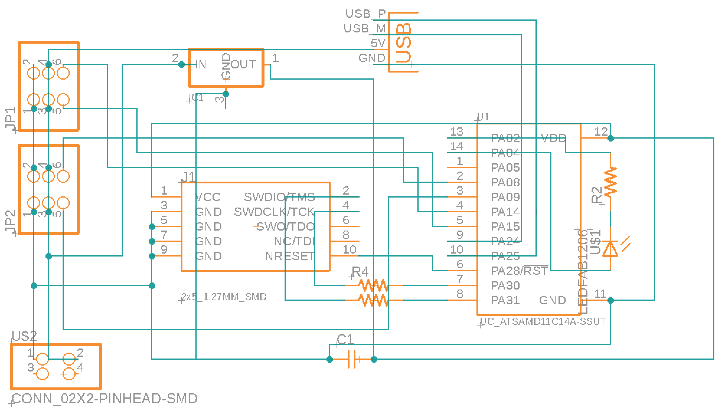
The goal for this project was to design, mill, and stuff a PCB that could control 4 motors. I chose to use an D11C microcontroller because it has enough pins for this board and it is easy to bootload and program.
Each servo has 3 pins - power, ground, and PWM for control, so I will be able to fit 2 servos in each 3x2 pin header.
Below listed are the parts used, in FAB Libarary titles:
IC1 t44: UC_ATTINY44-SSU
J1 ISP: CONN_03X2_AVRISPSMD
J2 power: CONN_02X2-PINHEAD-SMD
IC2 5V: VR_REGULATOR_SOT223
C1 1uF: CAP_UNPOLARIZEDFAB
J3 servo: CONN_03X2
Resistor: R1206FAB
xtal1 20mhz: XTAL_RESONATOR
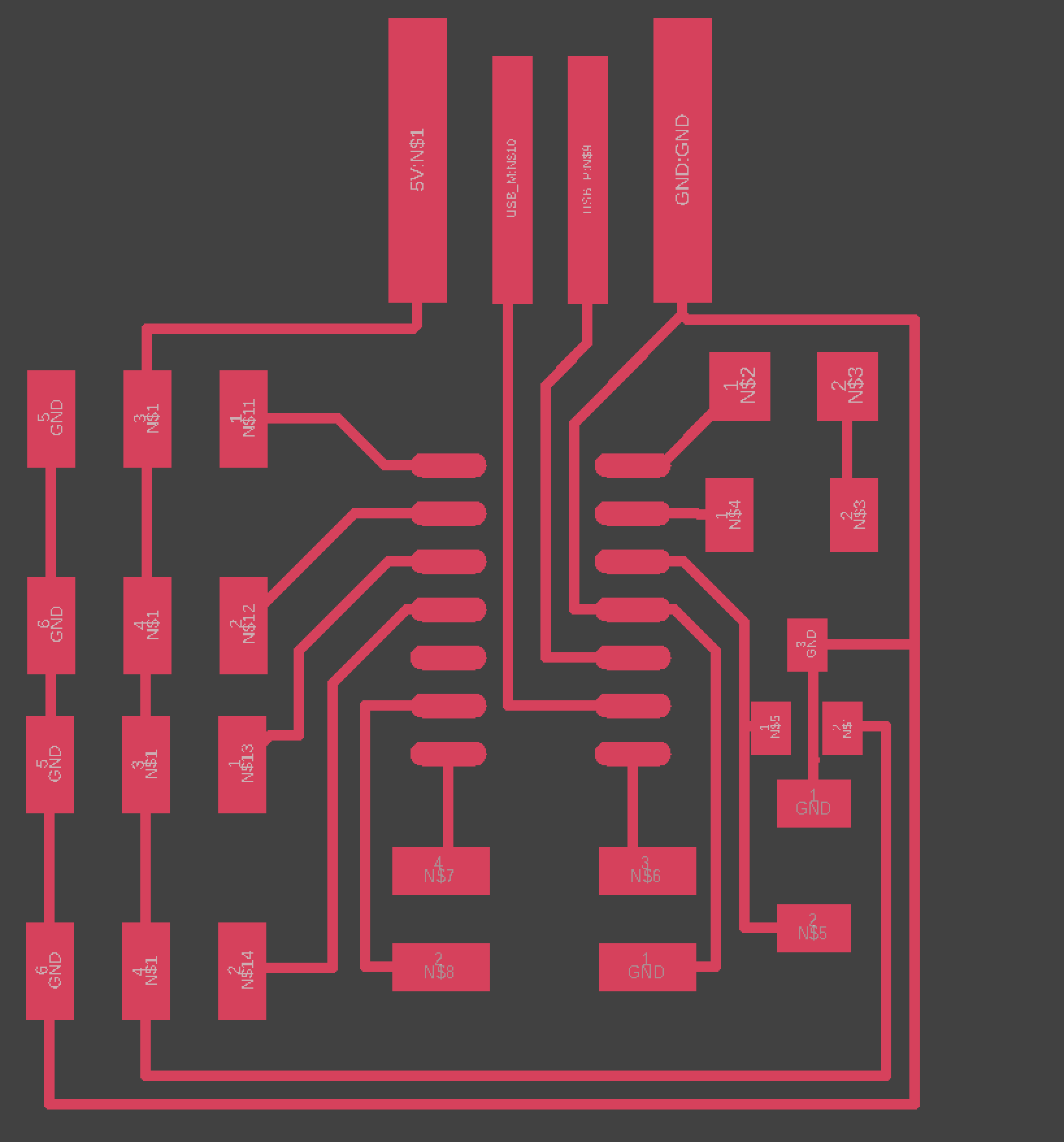
Eagle auto-creates 2 documents for every electronics design, a schematic and a PCB document. Starting with the schematic, I used the add command to pull all the parts onto the grid, and the net command to wire them.
Creating A PCB document automatically imports the parts and wires from the schematic. The next, and most time consuming process, was wiring the nets so that they dont intersect.
A trick I like using to simplify this process is using 0 ohm resistors to cross wires. In my first attempt, I copied Neils hello.servo.D11C board, but when I milled it, many of the tight traces were fused.
After going to office hours, I learned that Neil's pads are smaller than the FAB library pads in eagle, which allows him to net 4 wires through the middle of a D11C.
My first solution was using a 4-pin header instead of the standard 2x5, a strategy I've seen in a few example boards.
However, after milling and stuffing, I learned that 2x2 pin headers are much more difficult to bootload as they don't conform to the ATMEL ICE pinout. I went back to Eagle, exchanged the 2x2 for a 2x5, and used some 0 ohm resistors to fix the wiring.
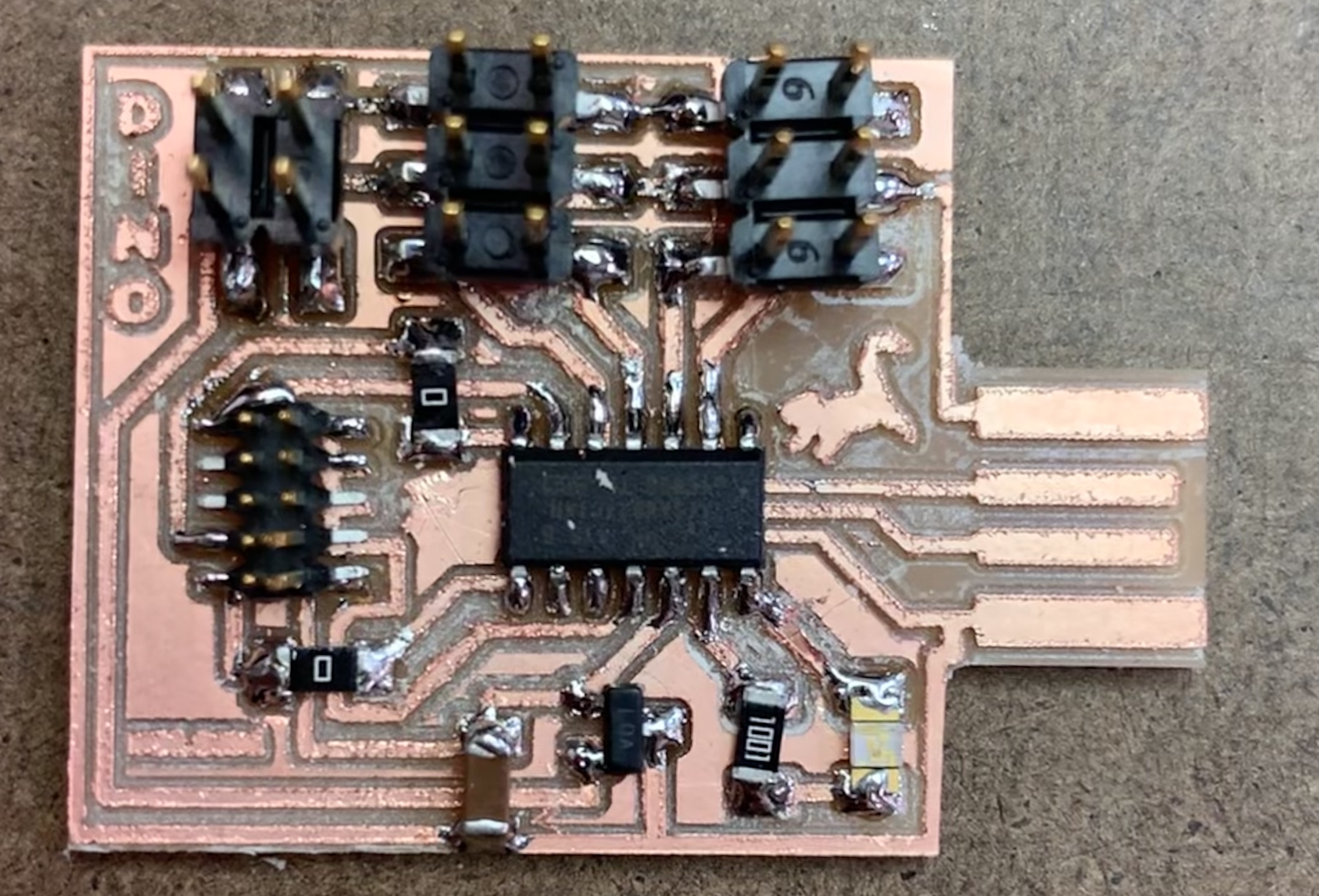
My final board features 2 3x2 pins to fit 4 servo motors, a LED and current-limiting resistor, and a USB port to connect to my mac.
I am expecting 4 servo's powered through USB to put a significant strain on my macbook, so I included a 2x2 pin header to connect to a wall outlet, and I will slice the 5V USB trace if I decide to connect to wall power.
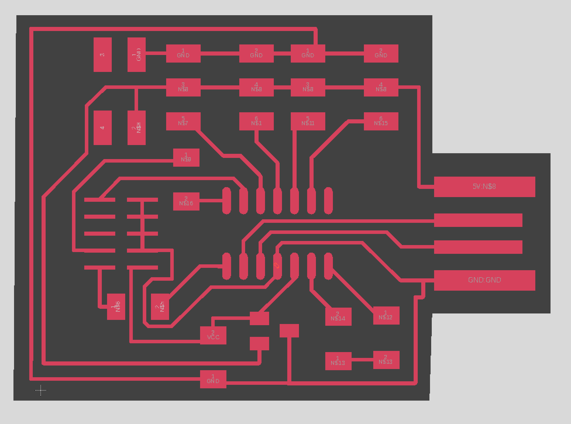
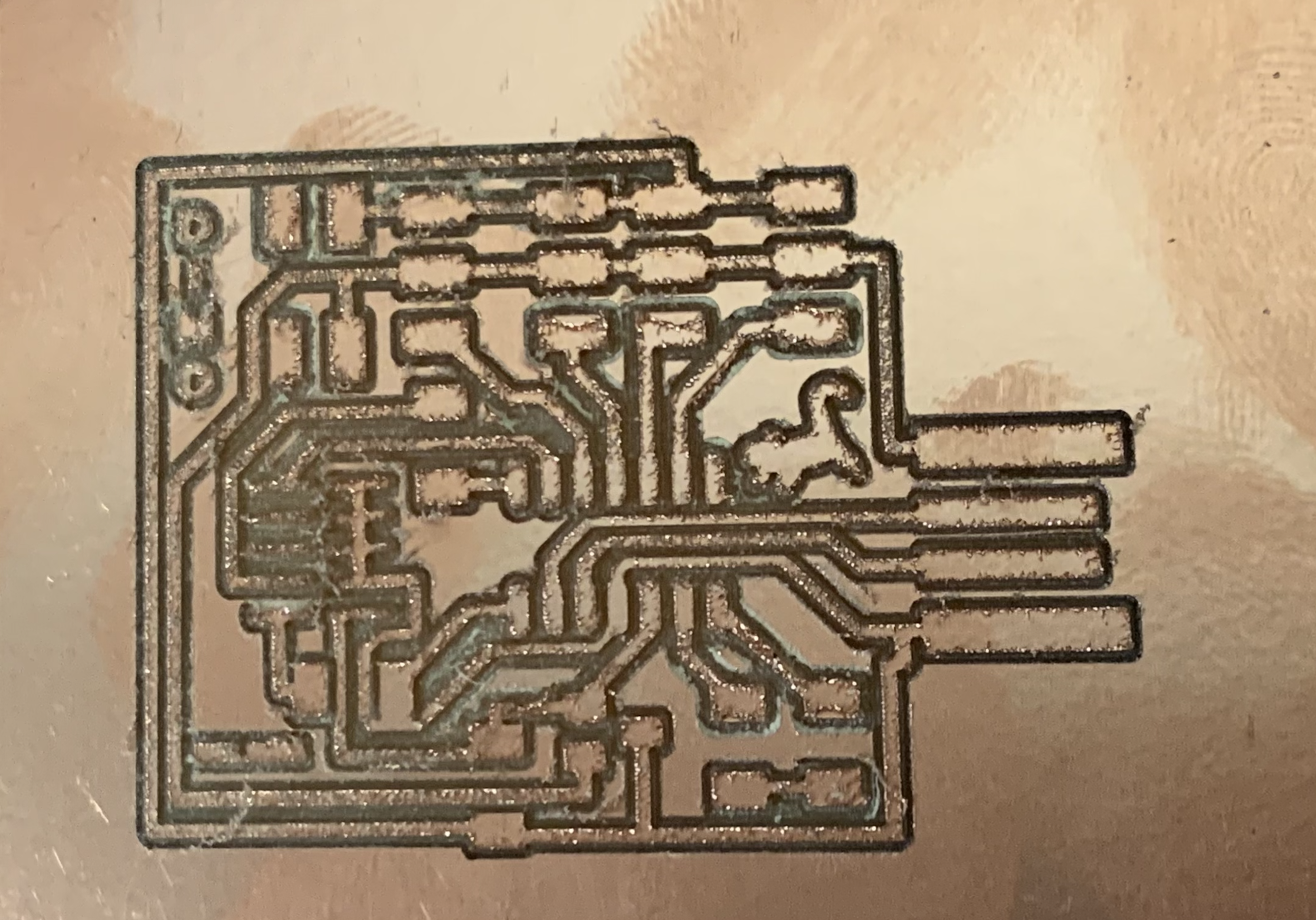
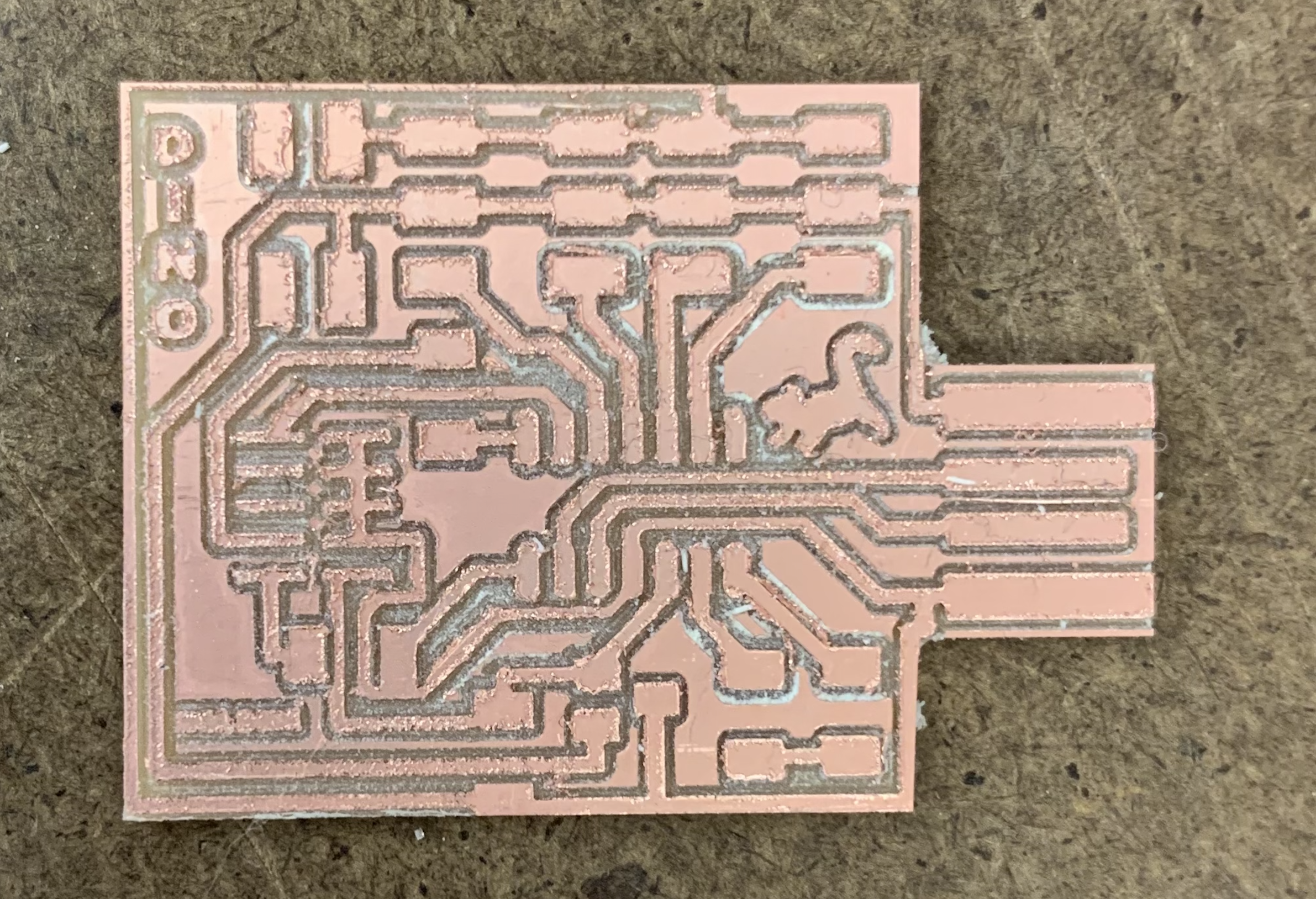
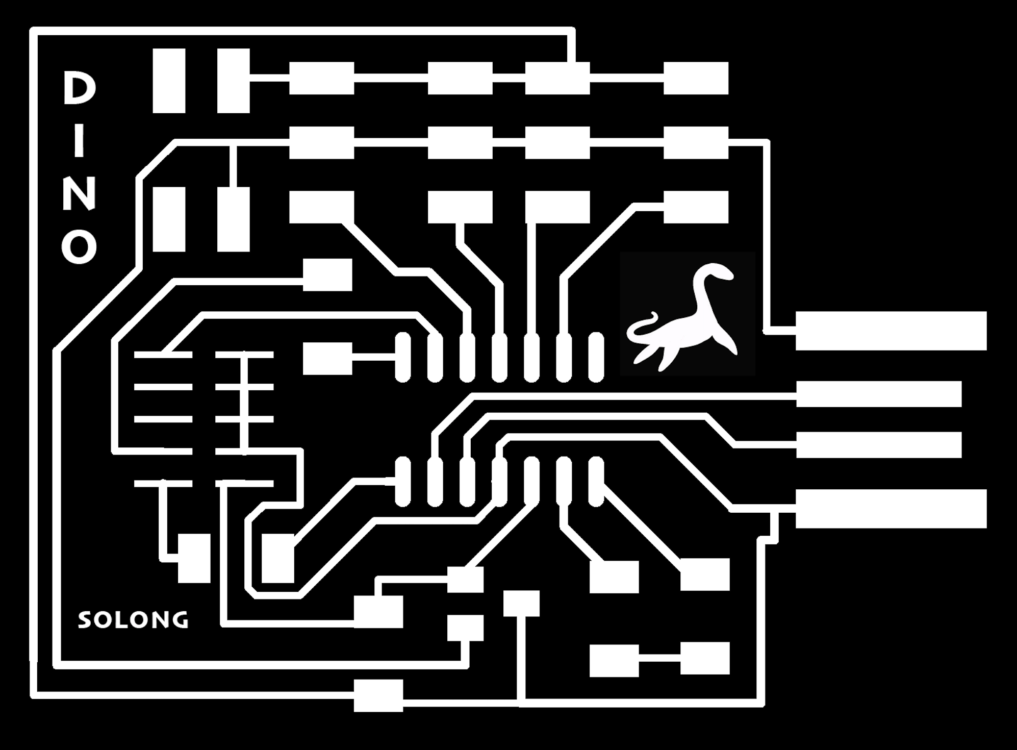
To export a trace and outline, I used the polygon command in layer 20 to draw my border. Commands display none followed by display top vias pads and lastly export image with the setting set to monochrome and 1000 dpi exported my final trace.
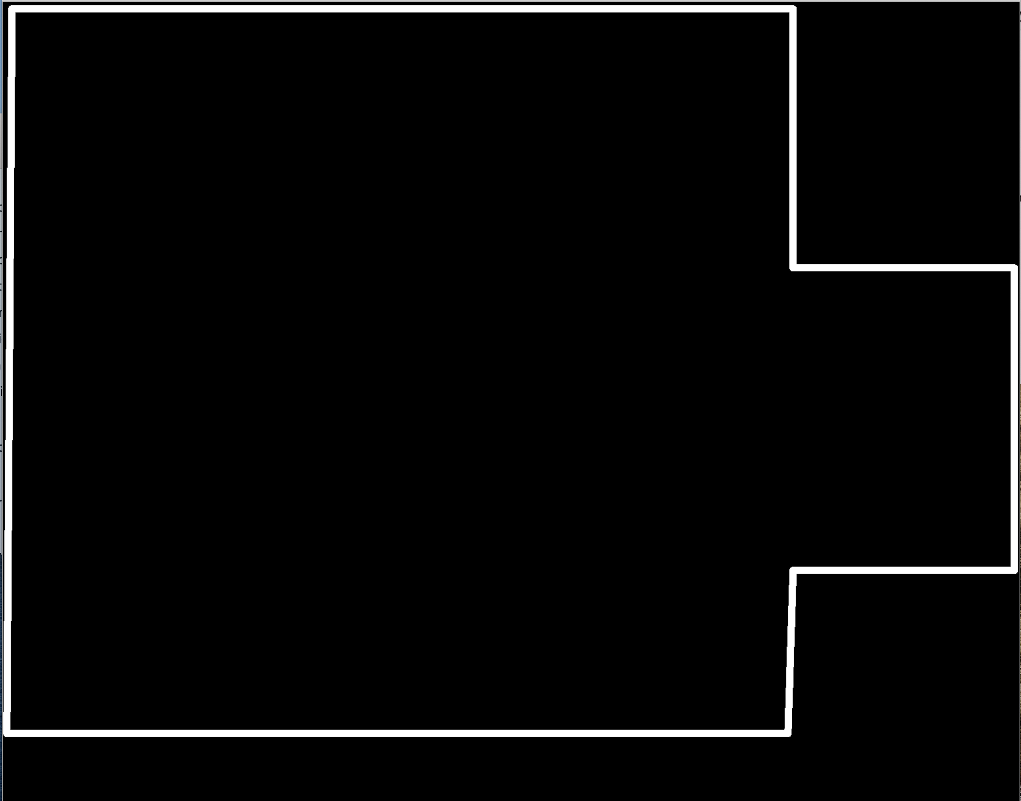
Similarly, I used display none followed by display bottom dimension pads and the same export settings I used in my traces to export my outline. In photoshop, I added a dino and some text. Here is my final trace and outline:
Milling
To mill my board, I used the Roland SRM-20 mod (mods.cba.mit.edu) to connect to the Roland.
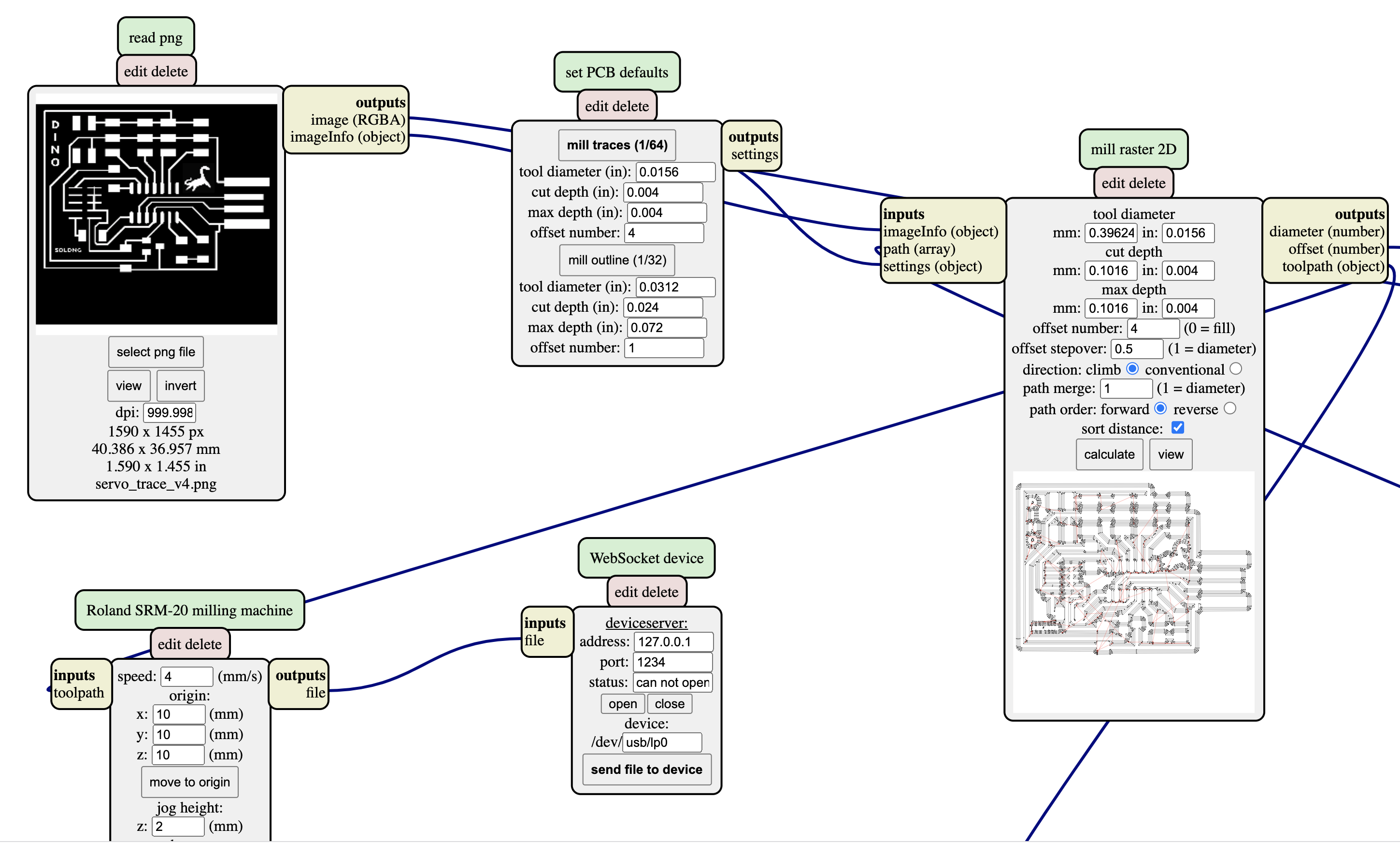
Here are the steps I followed:
1) Read PNG: select file. When exporting eagle images on a mac, sometimes you need to double the dpi (2000) to adjust for scale.
2) Set PCB defaults: Select 1/64 to mill the traces.
3) Mill raster 2D: click calculate, and compare the toolpath to your png to ensure traces don't get fused.
4) Use double-sided tape to secure a peice of copper to the floor of the machine. Gently secure a 1/64 toolbit, making sure not to drop it.
5) Set origin: I always move the origin to the bottom left corner to save copper space.
6) Unscrew the 1/64 toolbit, gently press the tip into the copper with your fingers, and screw it back in.
7) Websocket Device: open the socket, check that the connection was accepted in the terminal window. Send file to the device.
8) Without moving the copper or changing the origin, repeat the above steps with a 1/32 toolbit and the 1/32 PCB default.
The 1/64 bit was dull, so the edges of my traces came out scraggly. Using a flat tool and very soft sandpaper, I scraped the top of my board to smooth out my traces.
Soldering smooth and shiny joints was a fairly smooth process after all the practice I've gotten as a result of this class. To make the USB fit into a computer port, I cut some vinyl to place on the backing.
Here is a before/after: