Pixel Art Frame
Final Project: Proposal, To-dos, and Prototype process documentation
Table of contents:
for final project
Files
01 Proposal
//
Brainstorm & Sketch
For the final project, I decided to discard my idea that I had during the computer aided design week, and work on something cooler. My new idea is to make a pixel image canvas.
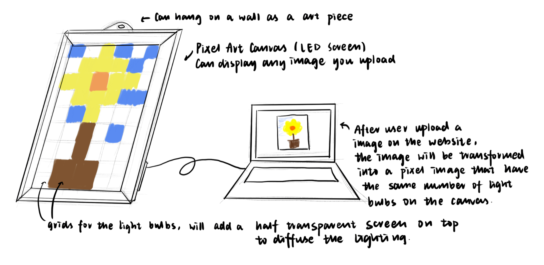
The pixel art canvas is made out of many full color LEDs placed within a art frame. When the user upload a image on computer, the software end is going to covert the image into a pixel image, and send all the necessary information to the hardware end in order to display the image. The image can stay as long as the battery dies out or user changes the image. It can also be hanged on a wall as a art peice.
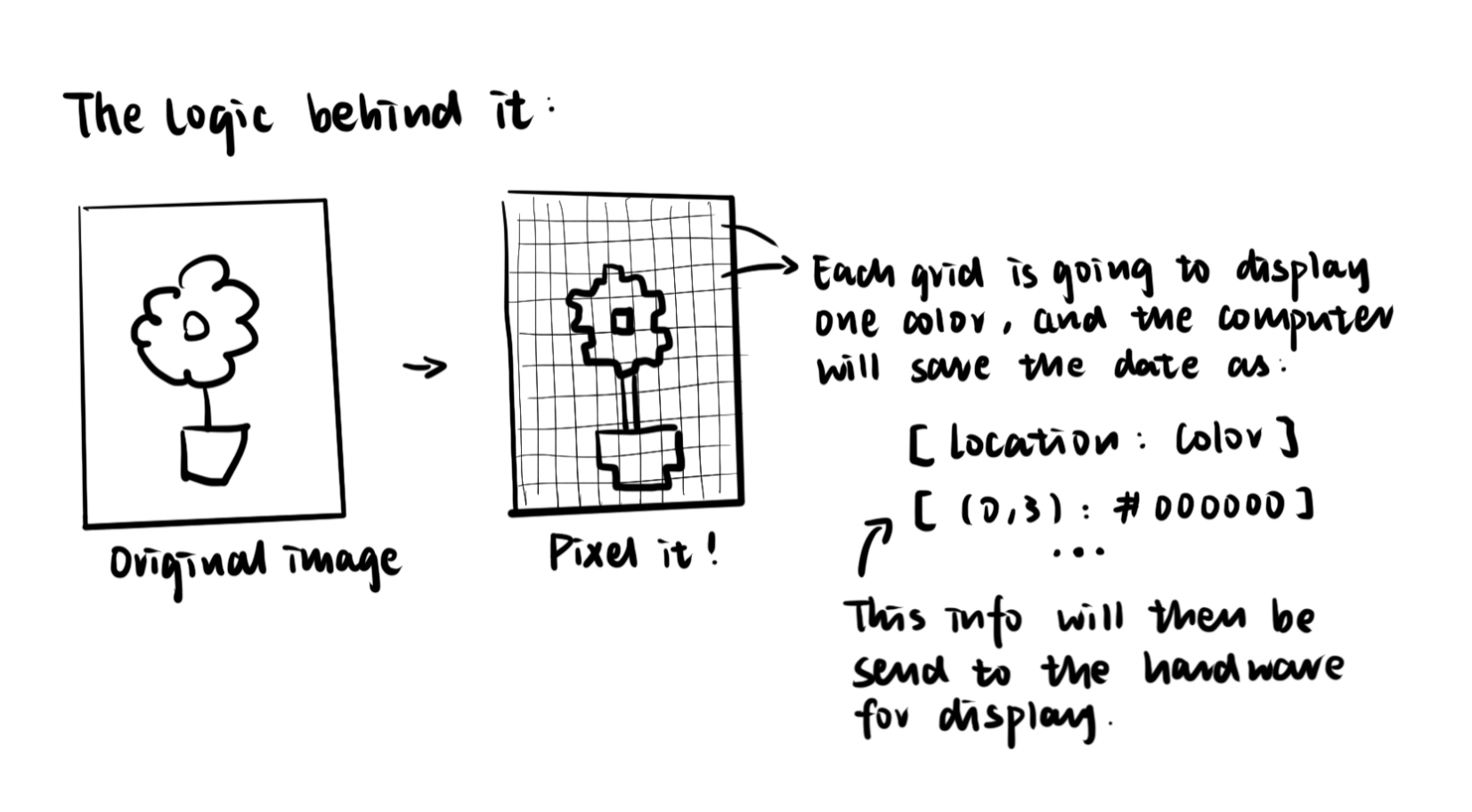
The logic behind the art frame is that the software will save the location and the corresponding color as an array of data, and will send these date to the controller to lit up the corresponding LED. In terms of materiality, I want to use acrylic as the main material for constructing the grid and the frame (definitly needs testing because we don't want a very heavy frame). Also, I will add a layer of half transparent sheet on top of the grid to diffuse the color emitted by the LED.
//
Preliminary Model
I used Rhino to model out the structure of the frame. Overall the structure is simple, and not a lot of mechanical parts to be considered.
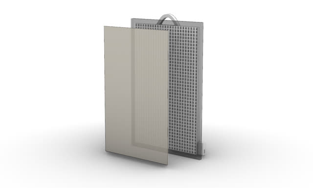
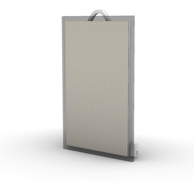
The size of the canvas is about 50cm*80cm, and there are 1000 grids. Once I have the full color LED parts, I will take a accurate measurement, and remodel with a proper grid size.

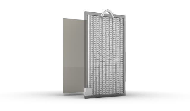
I will also need to drill out holes in each grid in order to solder all the wires. All the wiring will go to the backside of the canvas. I really hope that I can organize these wires well since there will be hundreds of them. I will also do some protytpes before getting into the big one just to see what is the most efficient way to wire and organize these bulbs.
//
Preliminary Interface Design
For the software end, I am going to design a website for user to upload and transform their image into a pixel drawing. I used Sketch as a UI design tool to create these templates for the website. If I have time by the end of the semester, I wish to create a simple phone app that can connect to the frame wirelessly so that users can just upload image more convinently.
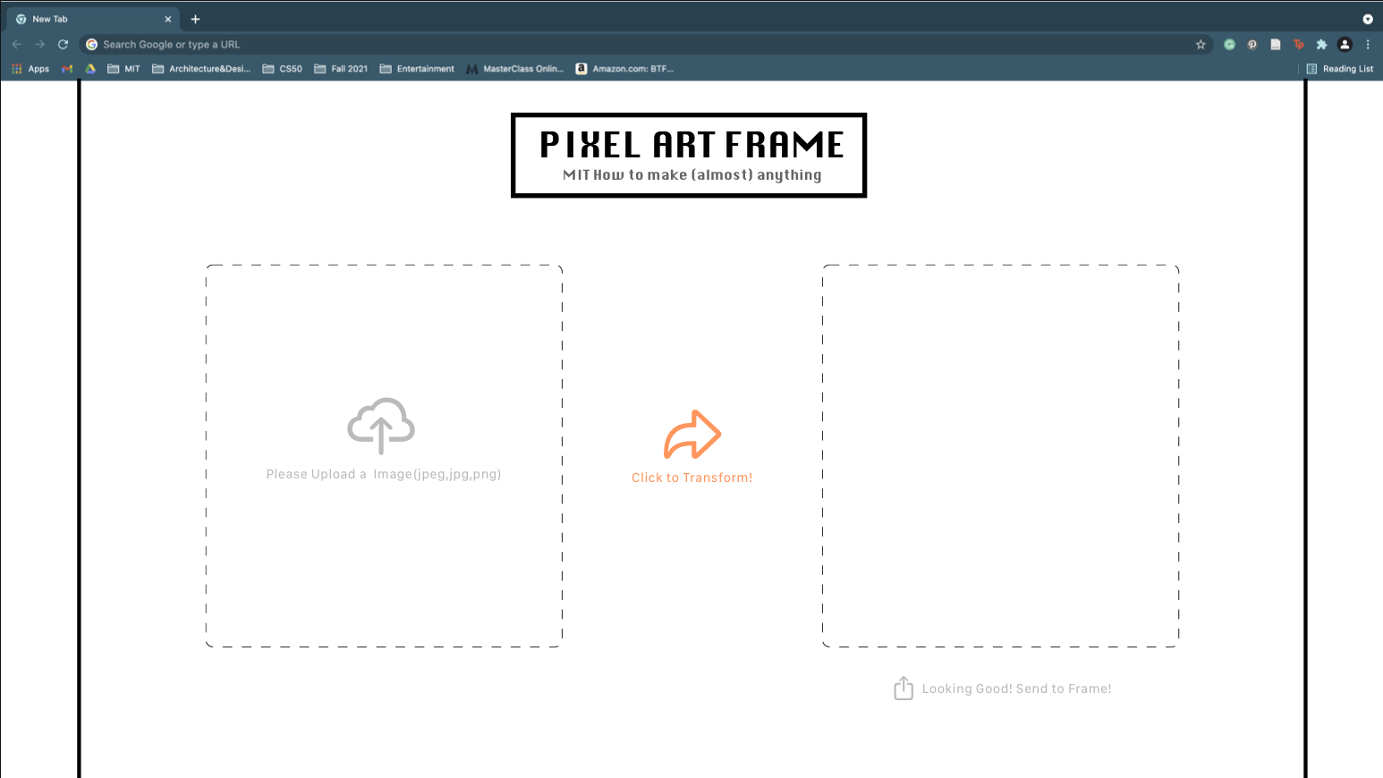
These is what going to look like on the user end. I want the process to be as simple as possible. I will use these as reference when I build the website for the frame.
02 To-dos
//
Software
✅1. Figure out how to produce pixel images.
✅2. Figure out how to store the color and location data and send it to the controller.
✅3. Store image and connect the input and output devices.
✅4. Figure out the final arduino program.
//
Hardware
✅1. Use laser cut to cut out the grid interlocking system (learned in week1).
✅2. Order some parts and start making prototypes of 6*6 grid.
✅3. Learn how to wire the bulbs.
✅4. Make the large scale final project.
03 Prototyping Process
//
10-13: LED testing and single grid prototype
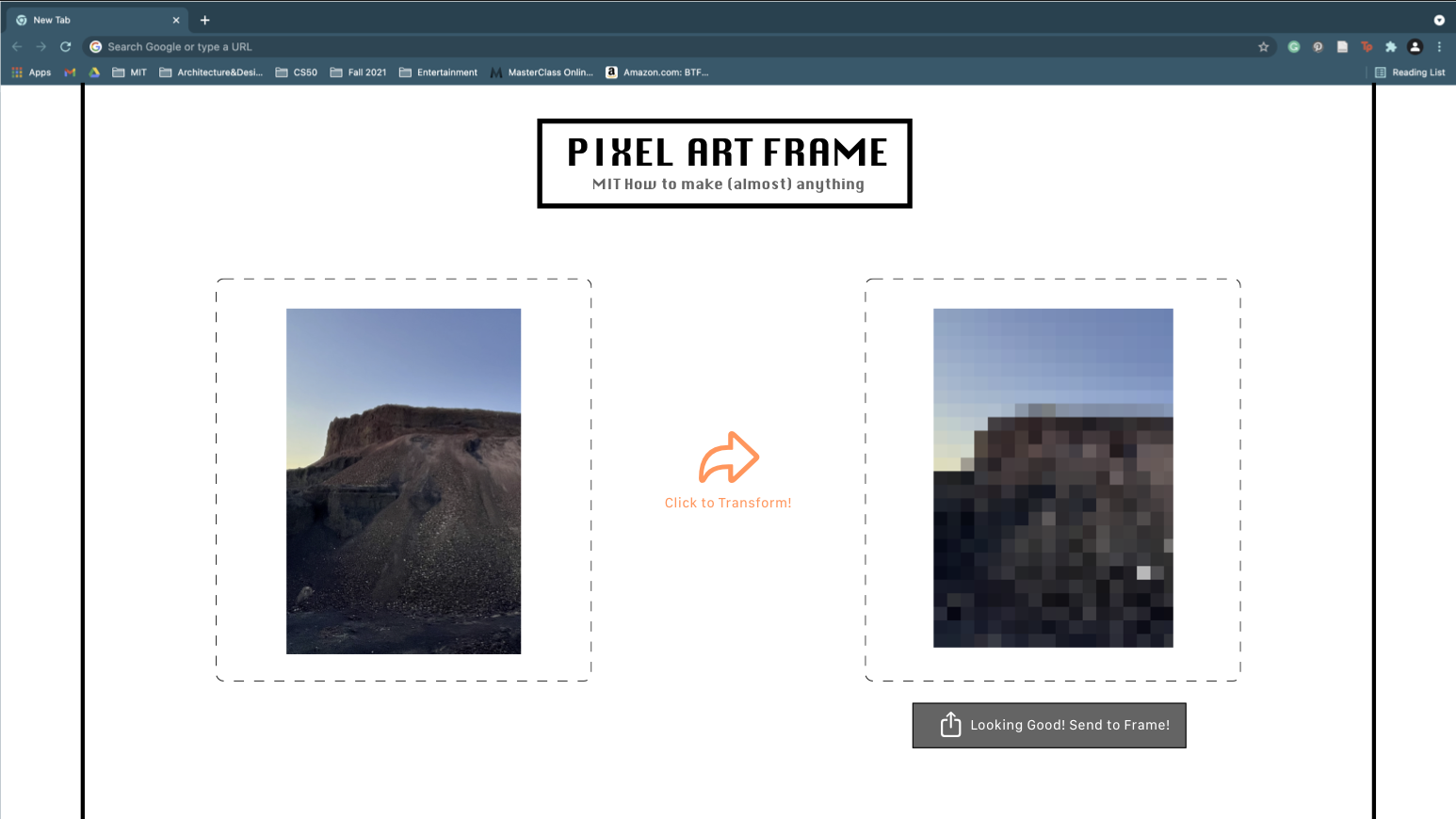
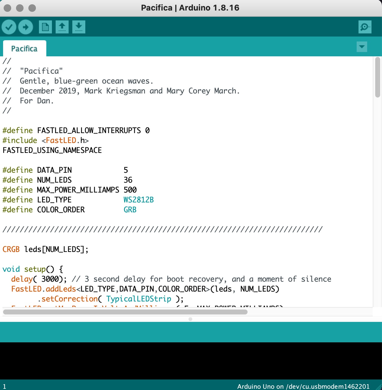
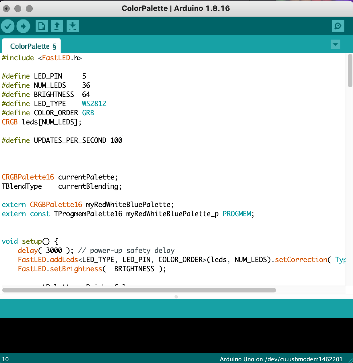
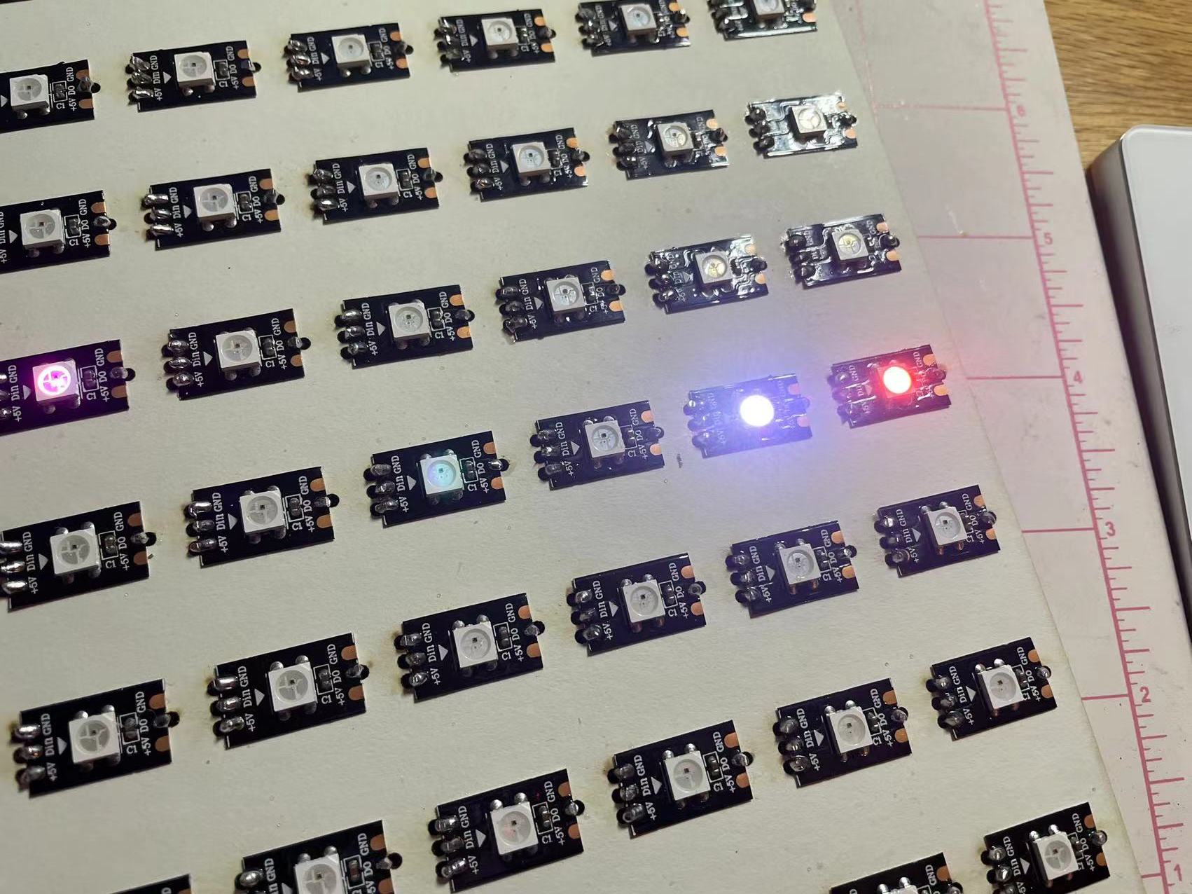
I ordered some digital LEDs and a arduino kit to start off my prototyping process. The digital LED I got was WS2812B RGM, which can diplay all kinds of color.
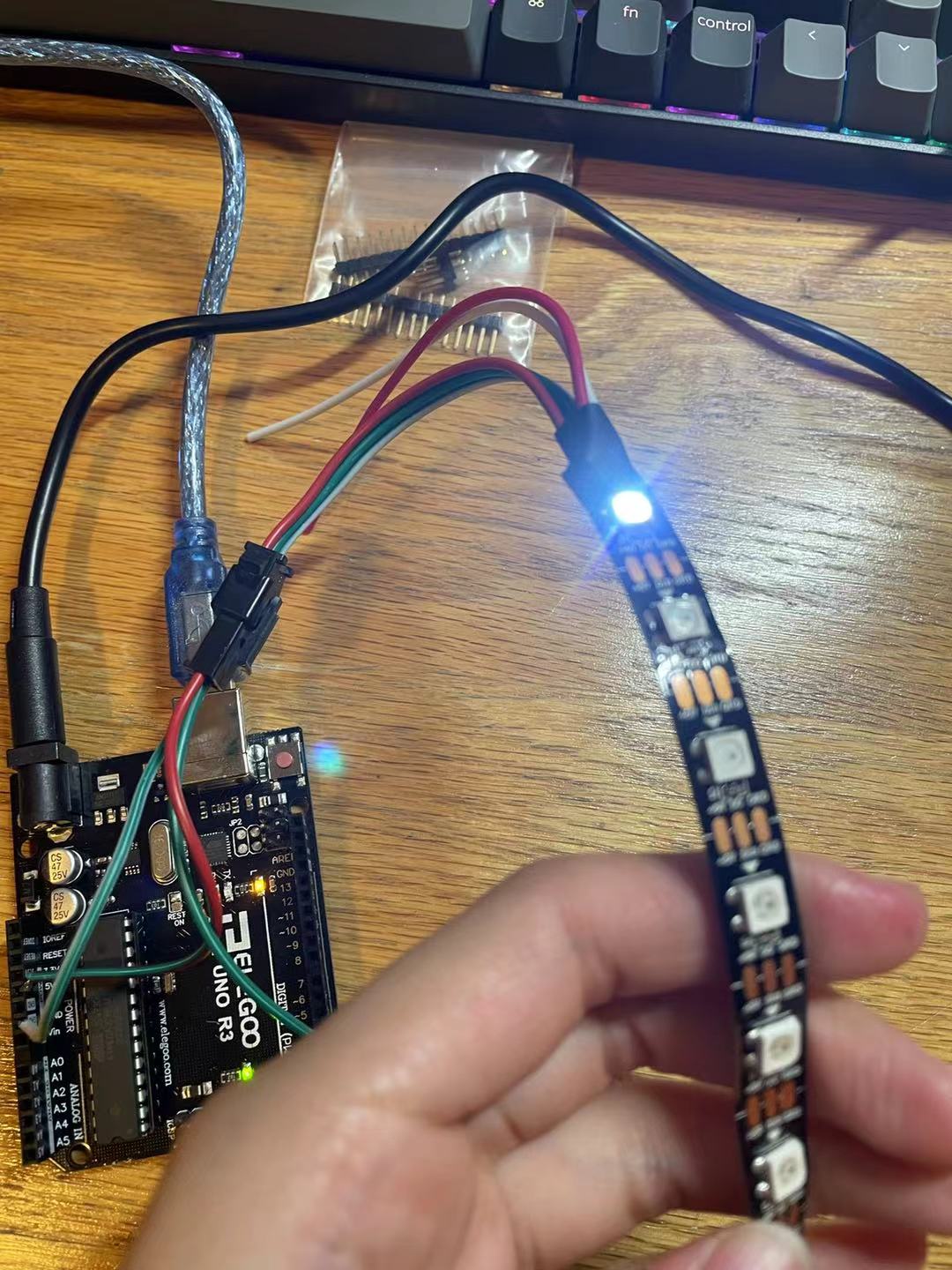
I uploaded a very simple code in arduino to check if all of the LEDs are functioning correctly. Since these are digital LEDs, which means they can pass down information when they are linked together, I can just connect them with one pin and controll the light on each of them individually.
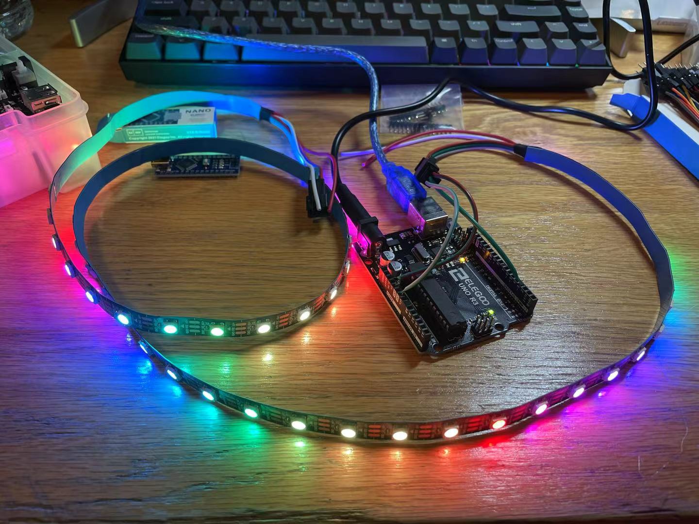
This is what they look like all lighting up together! I used some code from FASTLED library to test different effects.
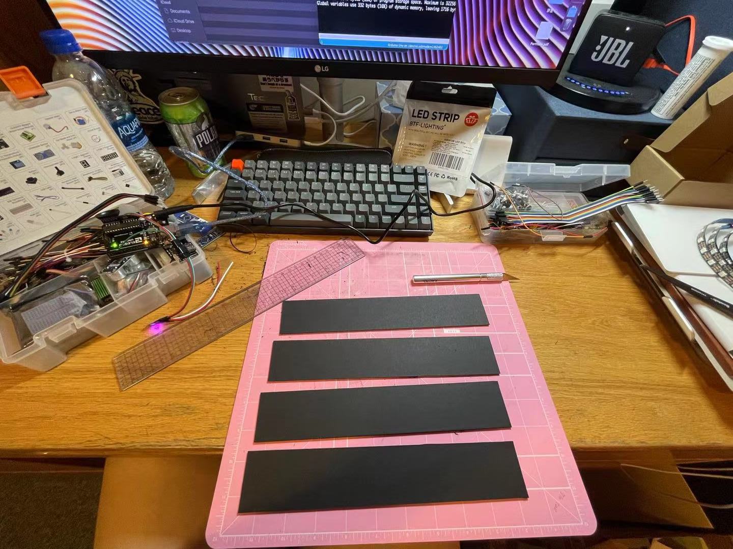
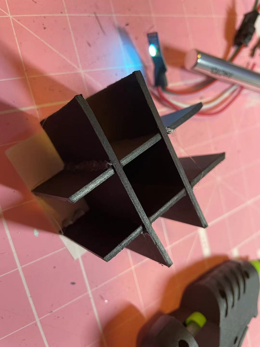
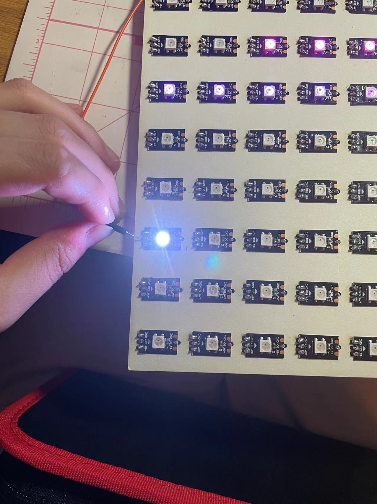
I then started cutting out some black carboards and made a grid for one of the LEDs. For this part, I want to know what is a good distance between the LED and the top surfaces so that the light will diffuse uniformly.
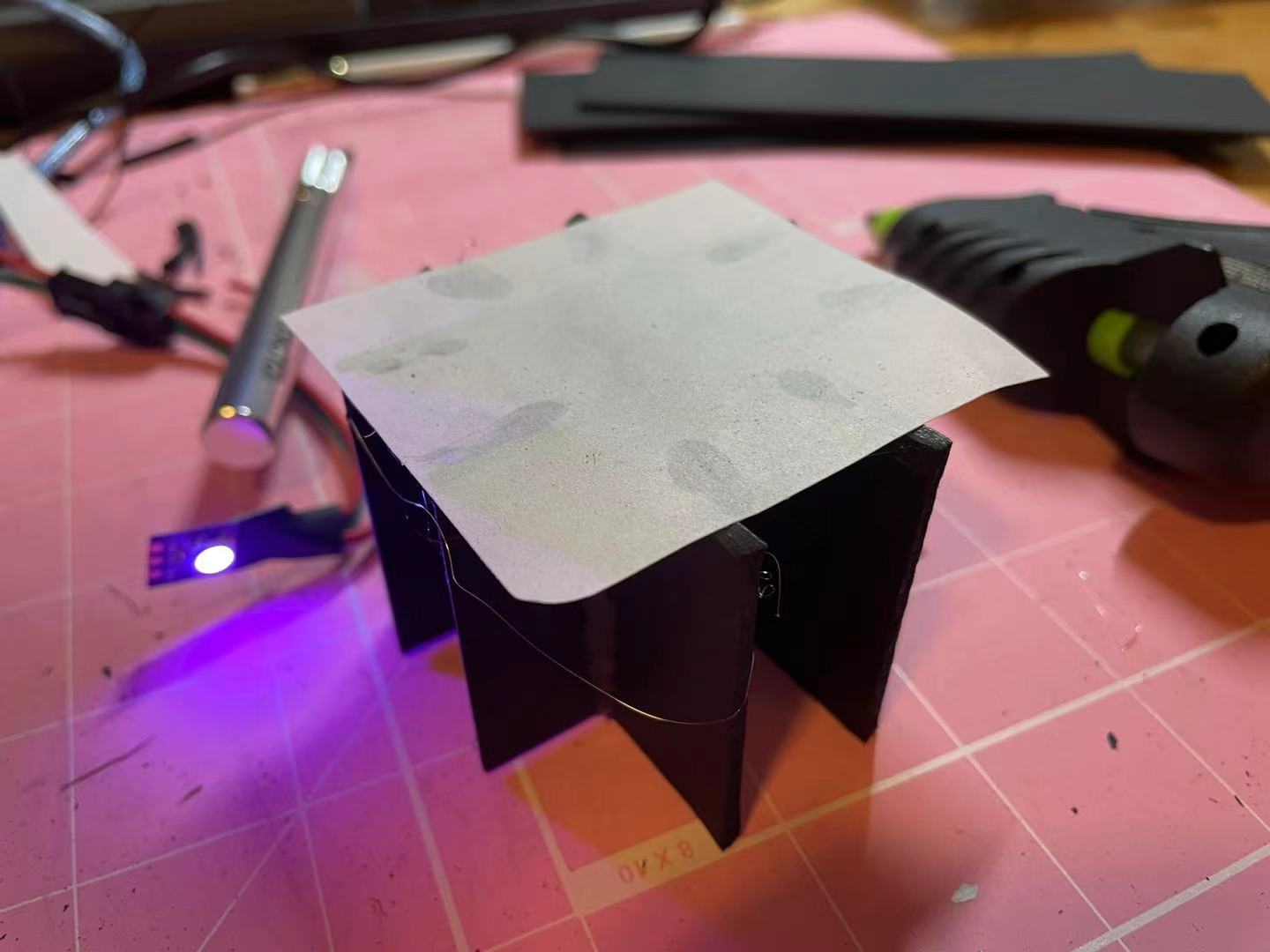
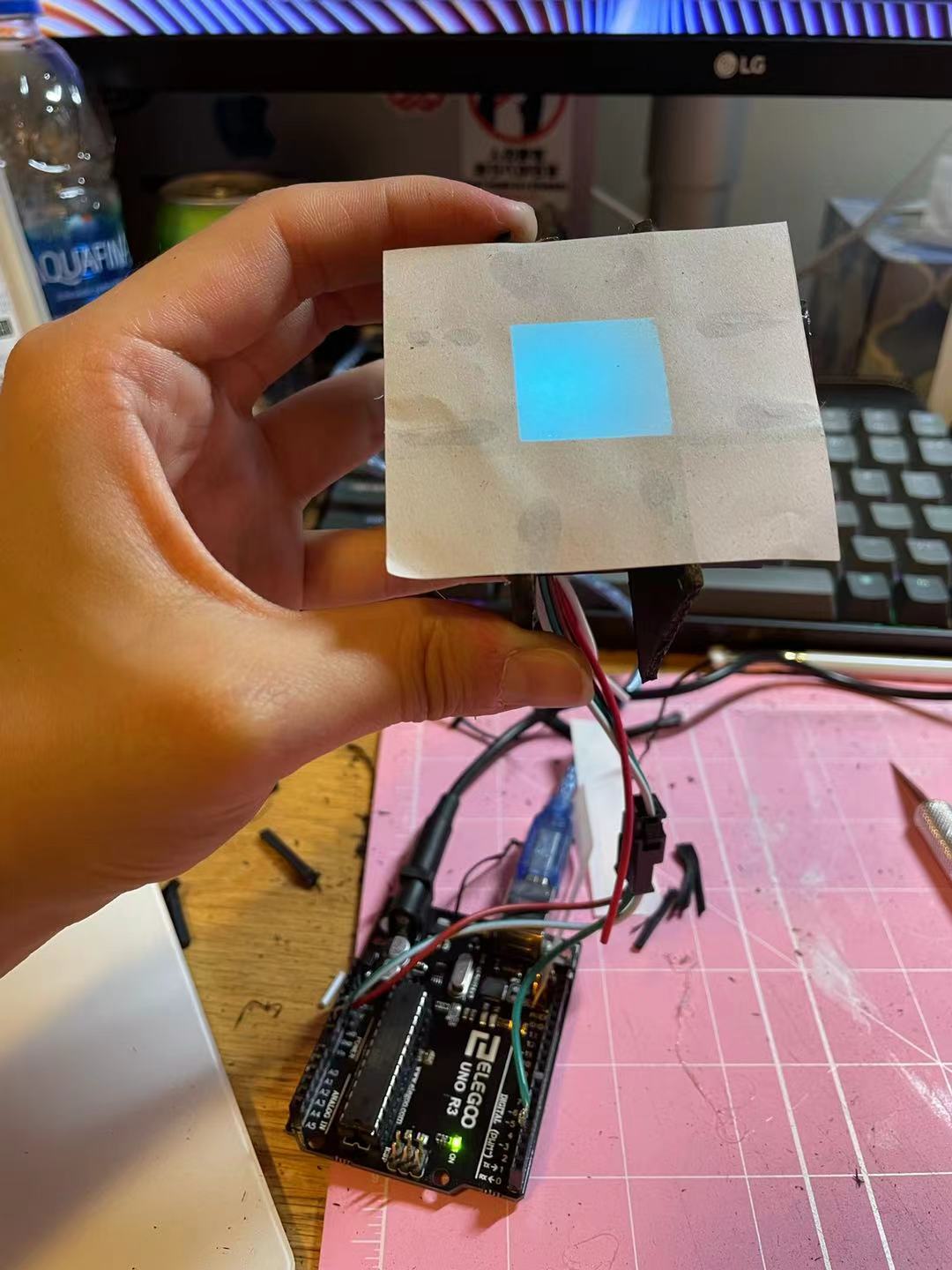
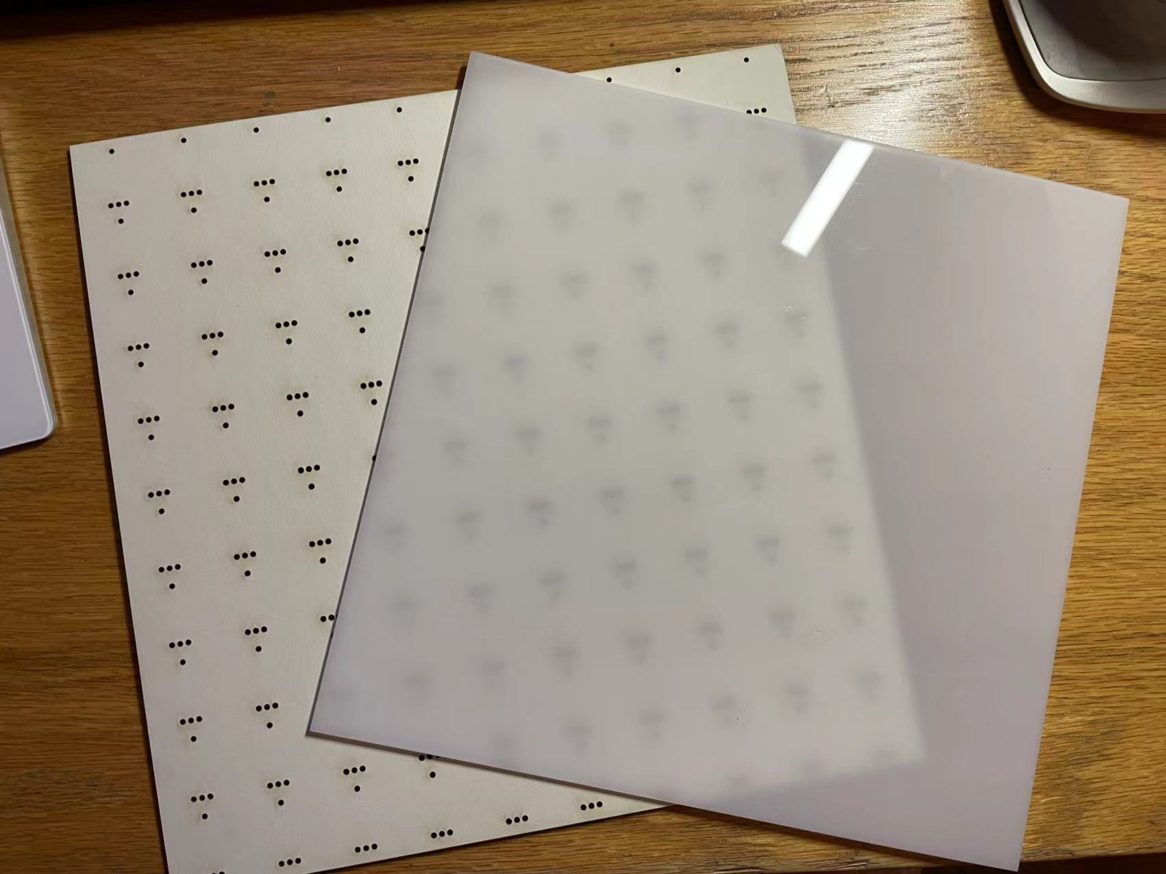
I have been using the white transparent drafting paper as the top finish to diffuse the light, however, it is very thin and easy to rip. I might change to white acrylic after testing. I inserted one WS2812 in the grid and determined that 2cm would be a proper length.
This is how it turn out in my grid! I am very statisfied with the result.
//
10-21: Fabricating the 6 by 6 grid prototype
I decided to make a 6 by 6 grid LED panel. To start with, I will need to make a main board and some bouding materials. I decided to use 3mm thich wood board and 3mm thick black cardboard.
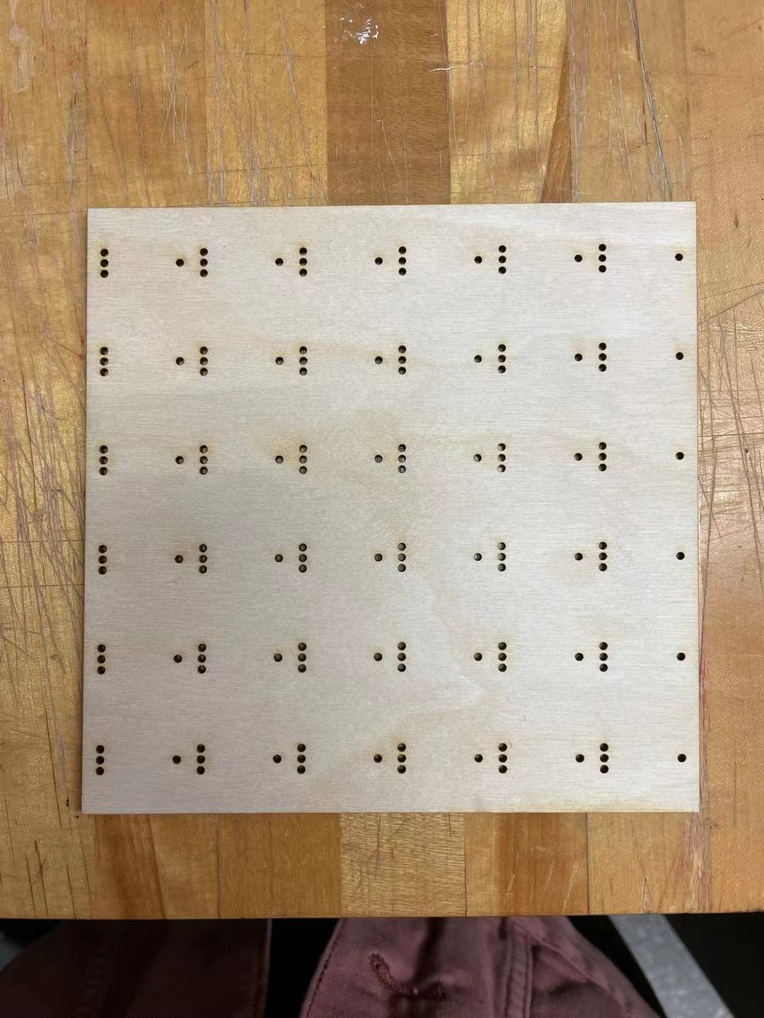
Using what we learned in week 1, I mapped out the holes in rhino based on the sizes of the LED and the bounding shapes and laser cutted them in the architecture shop. However, I forgot to account the kerfing and the black bounding peices fit together very loosely, so I might need to redesign that part.
I started glueing them down onto the board and assembled the grid although they are very loose.
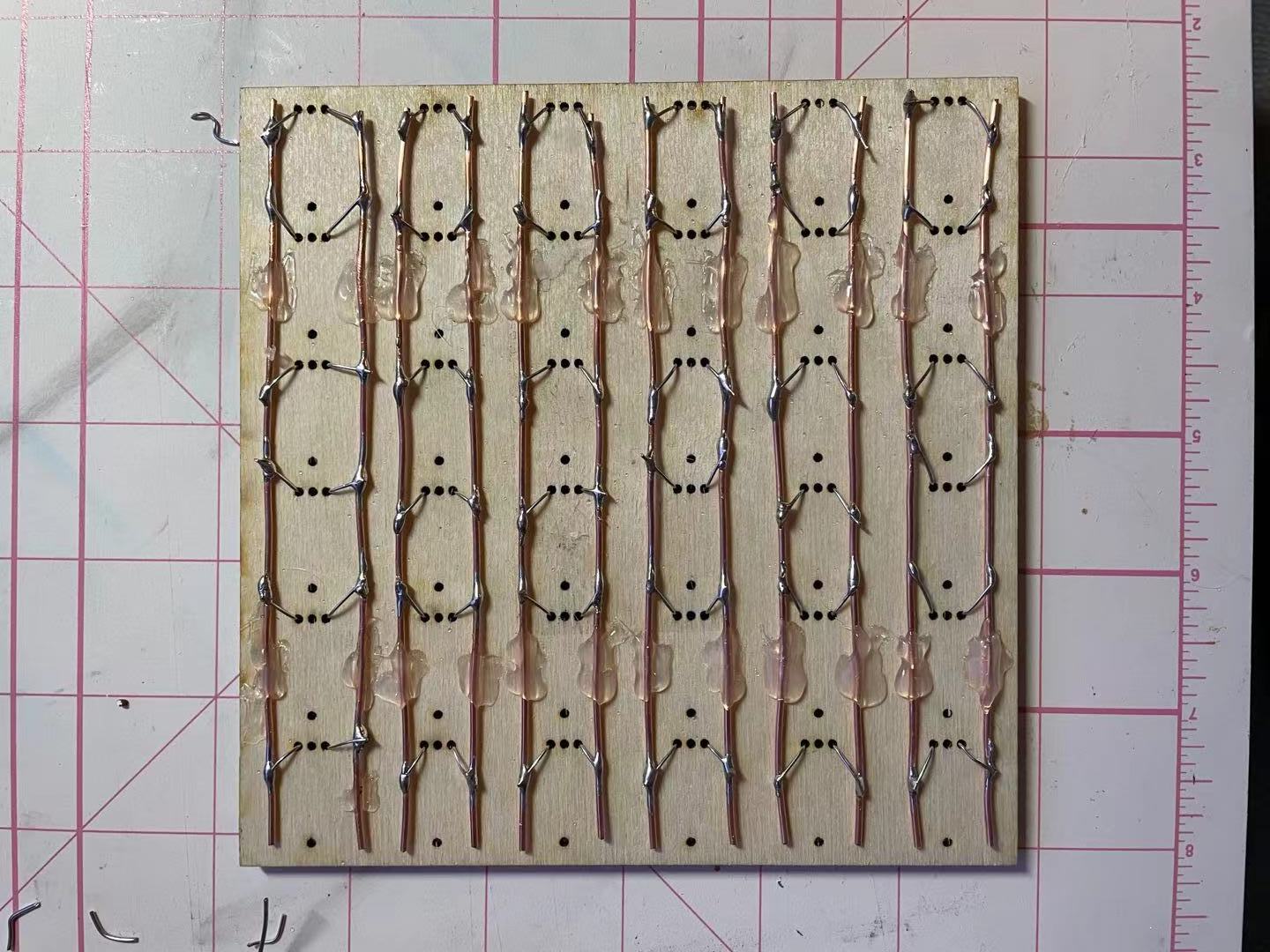
I glued some wires in the back of the board for soldering. Since this is digital LED, I can just link all of the GND and 5V togerther. I used a thicker wire as the main branches and soldered some thin copper wire between the LED and the main branches.
//
10-28: Continue fabricating the 6 by 6 grid prototype
Last time I connected all of the individual leds to groud and power separatly, so now I need to connect the leds together so that they can pass down informations.
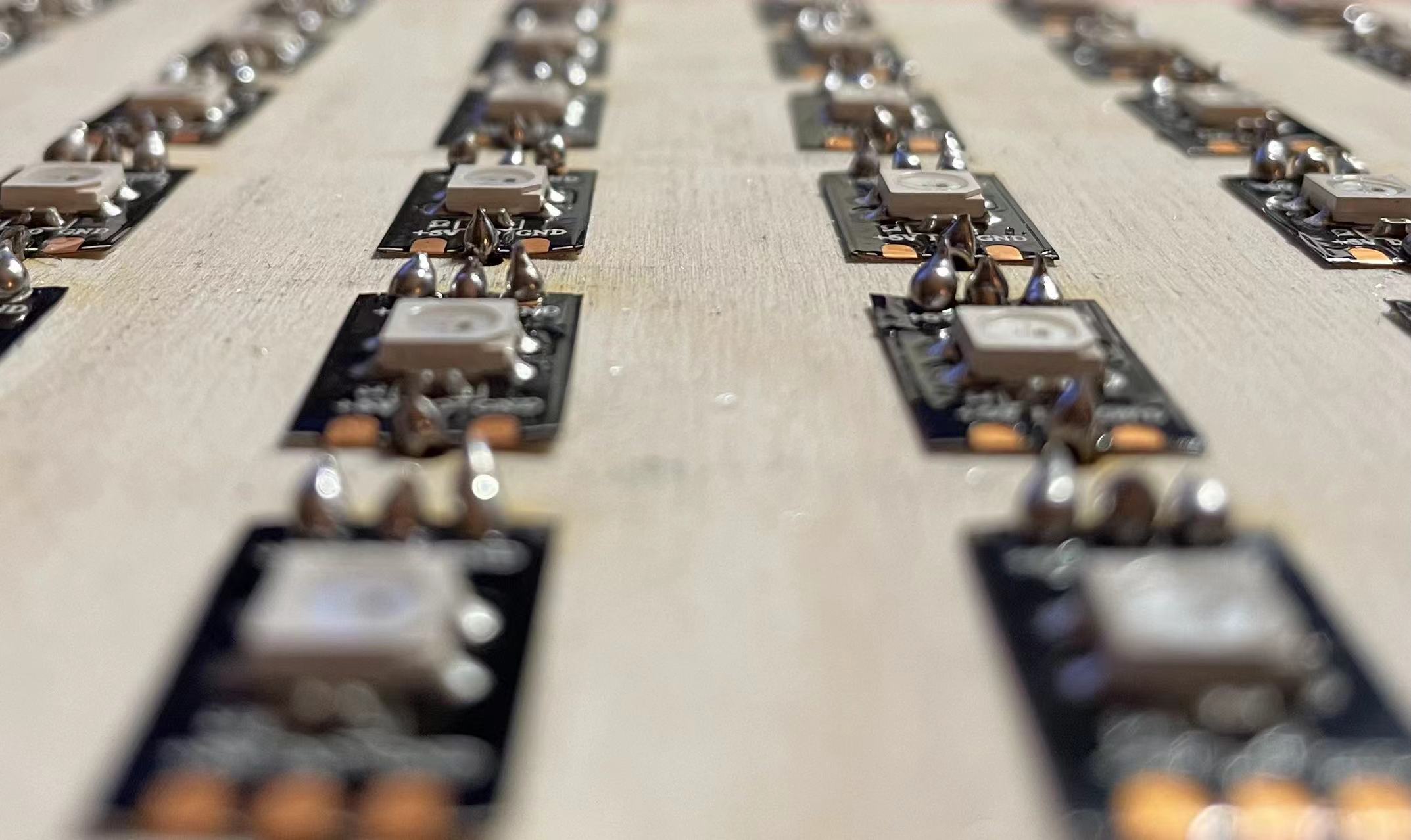
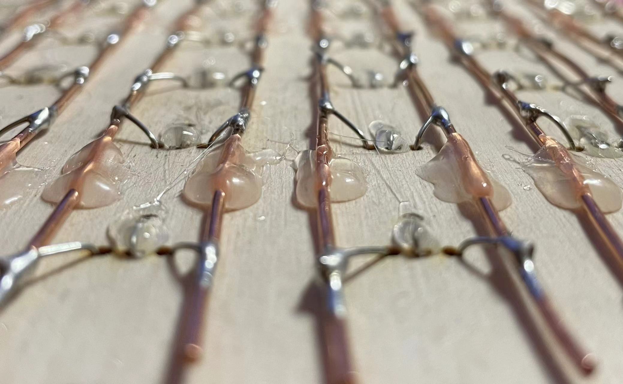
These are some detailed picture of the soldering. I used gluegun to secure and insulate the soldering and the wire.
This is how it looked after completed all of the soldering! It took like 6 hours for me to complete the entire process. One thing that is kind of hard to work with is that the hot iron would melt the glue, which makes the wire wiggle. Also, I will probably add some protection around the board to prevent the solders accidentally fire anything.
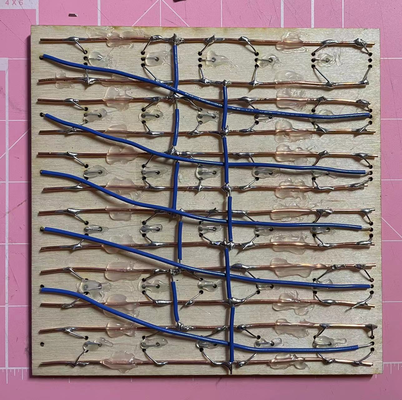
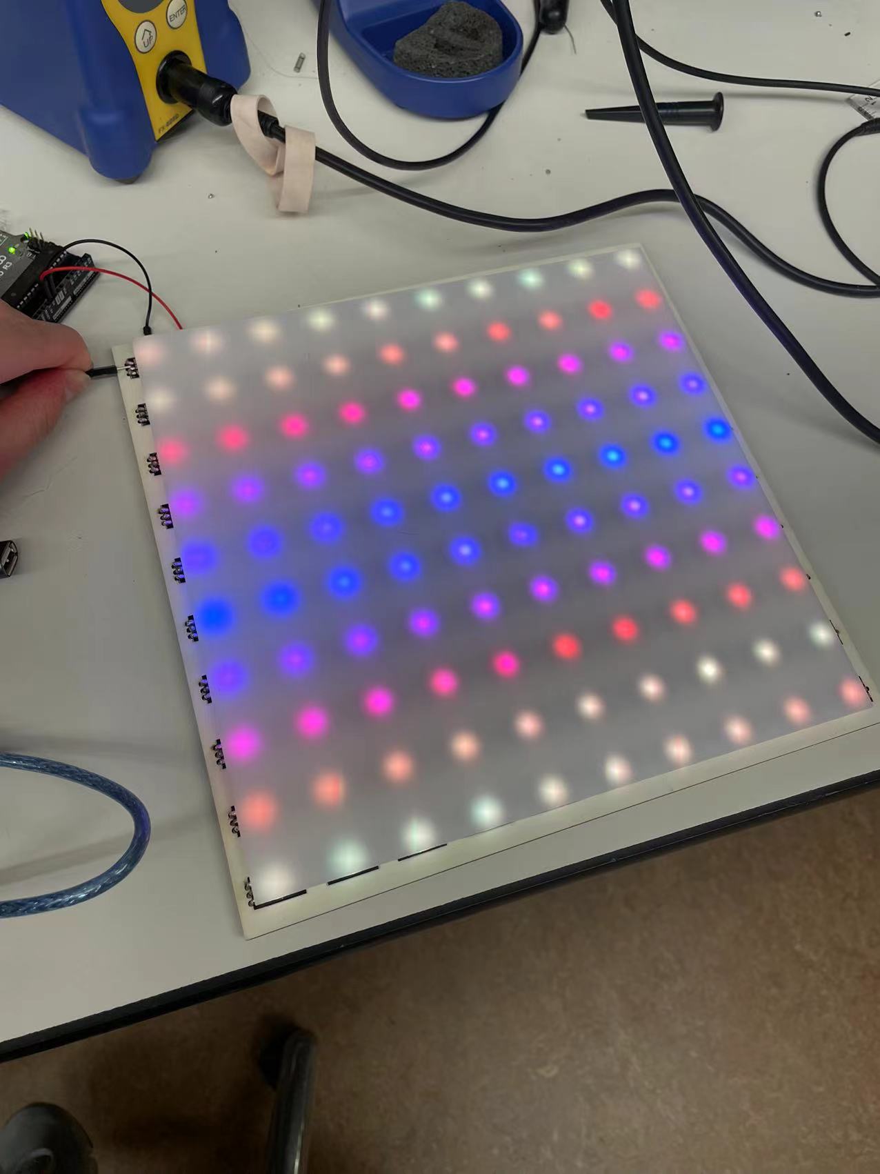
After wrapping up the hardware process, I uploaded a few programs from FASTLed and made minor changes to test the lights and their corresponding positions. I connected the led pins in "S" shape which follows how pixels are recognized in a image.
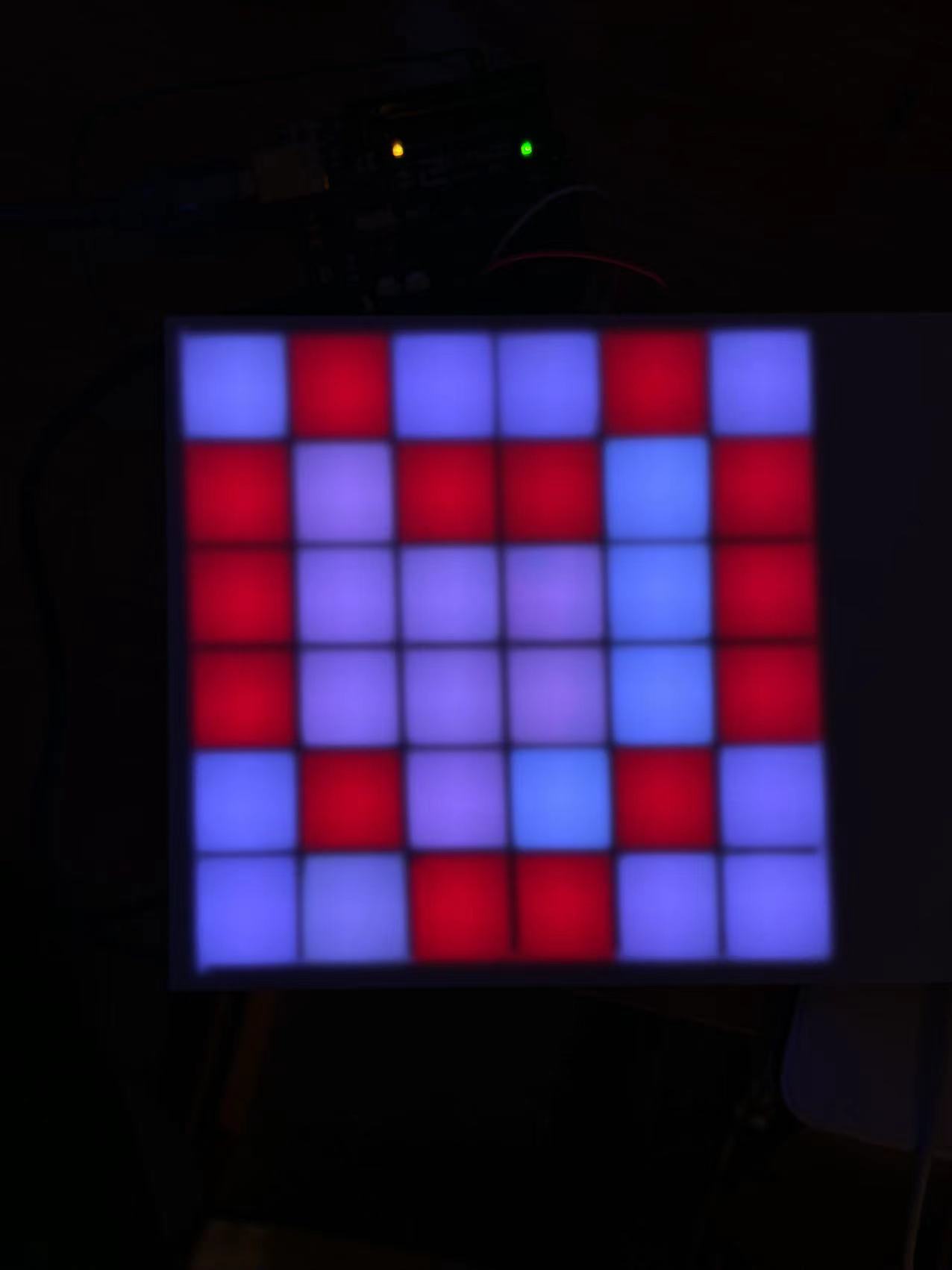
This is how it looks like without the grids! It works perfectly and all of them lit up according to their position.
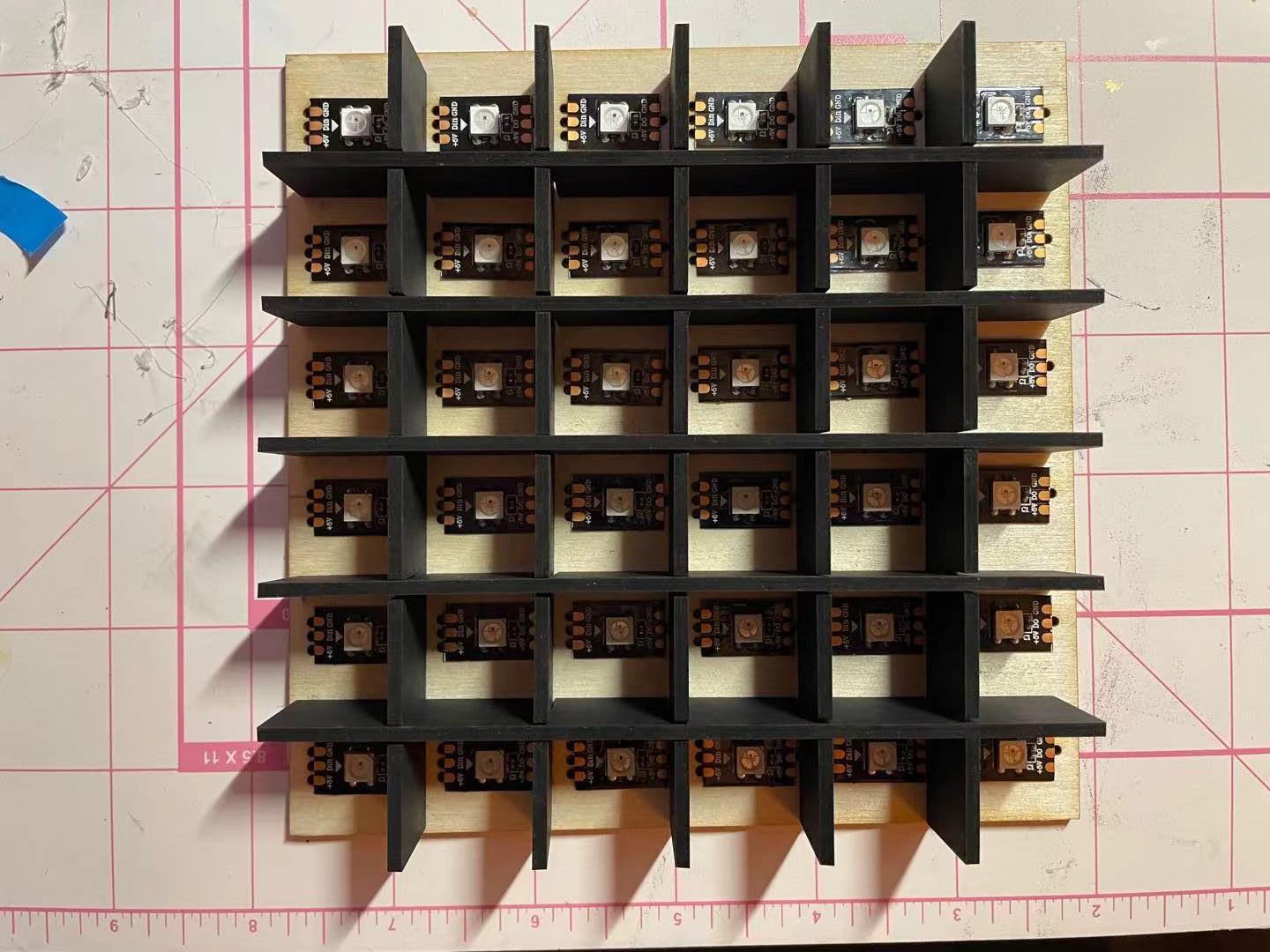
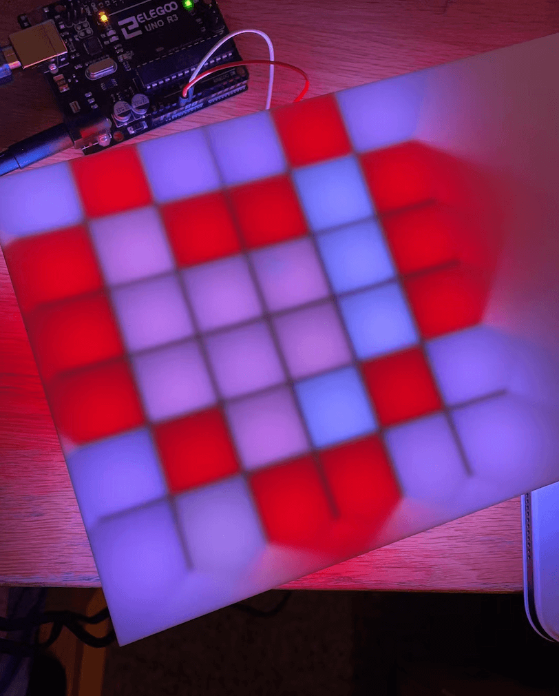
I added grids on top of the led matrix to distinct the lights. They are trapped in a square box which make them like pixels. I really like how this turned out and can't wait to do more experiments with these.
//
11-10: Programming and make art!
Now that I have the hardware part of my project, I decided to focus more on the software part. Calvin and Anthony gave me a lot of inspirations on how I can take a image or a drawing and transfer that into an array of information. I decided to create a 6 by 6 pixel drawing in inkspace and use processing to analyize the color data.
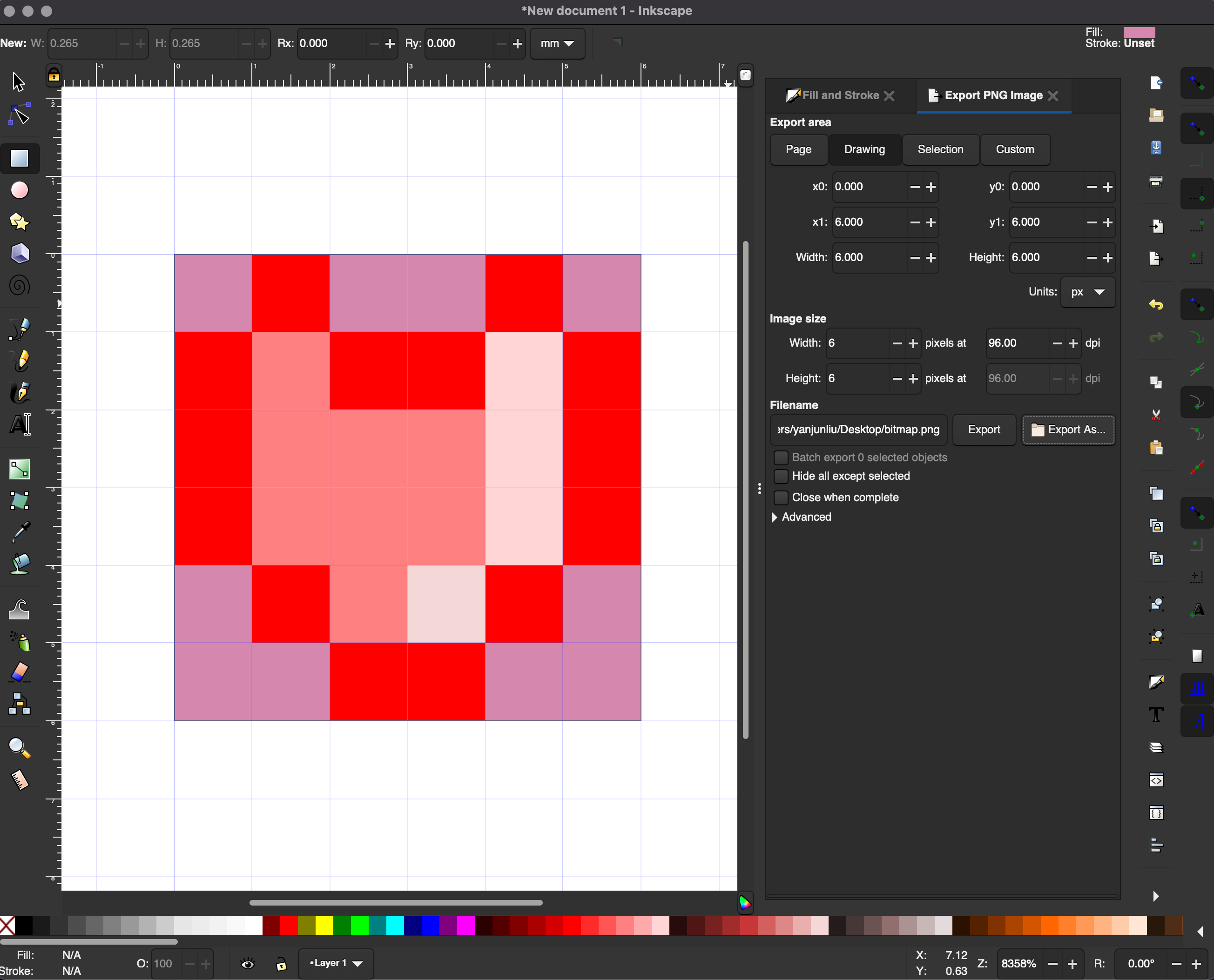

I set up a 6 by 6 frame in inkscape and used "fill" tool to paint a red heart. 36 pixels is extremely small and that is why the image on the right is very blurry.
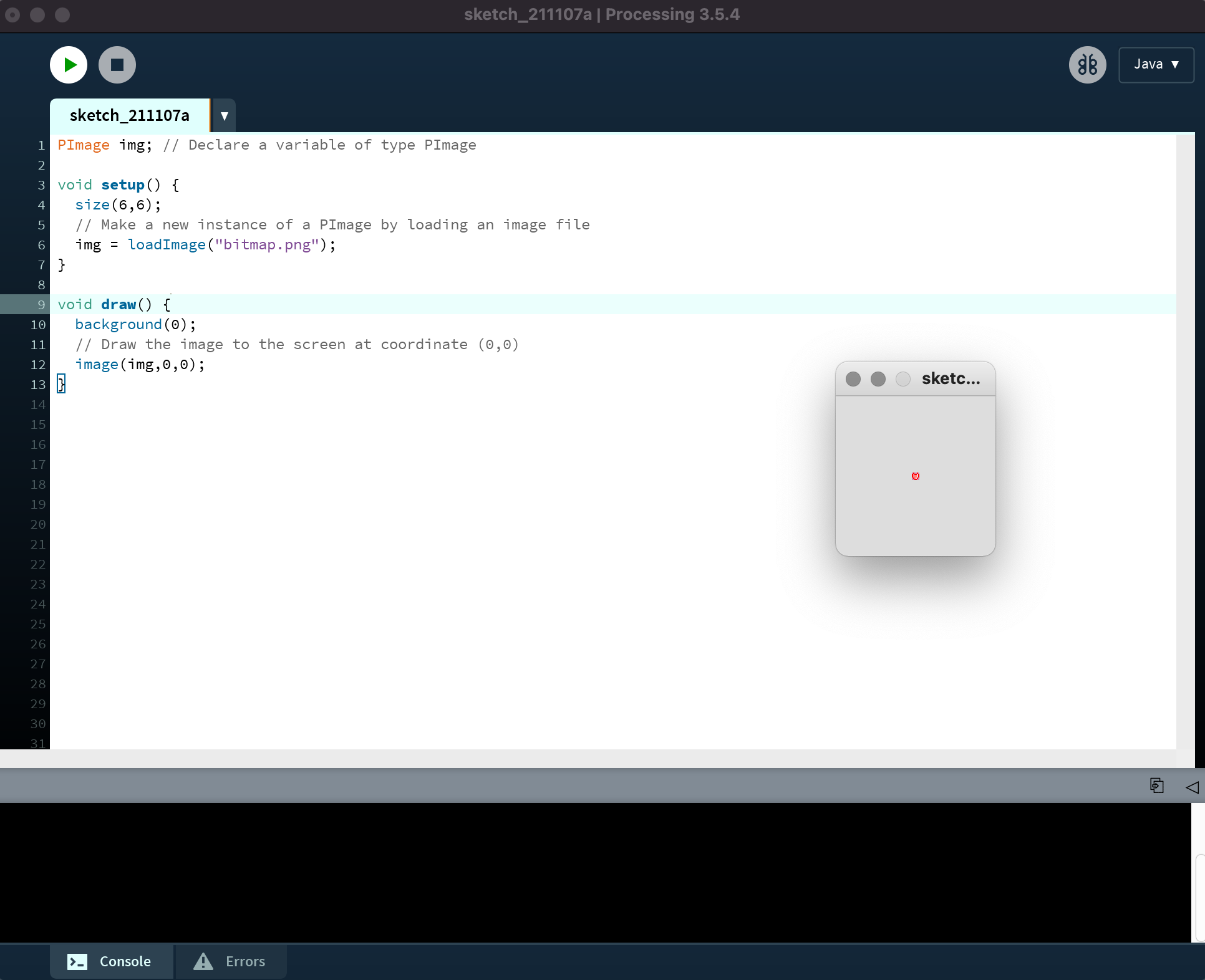
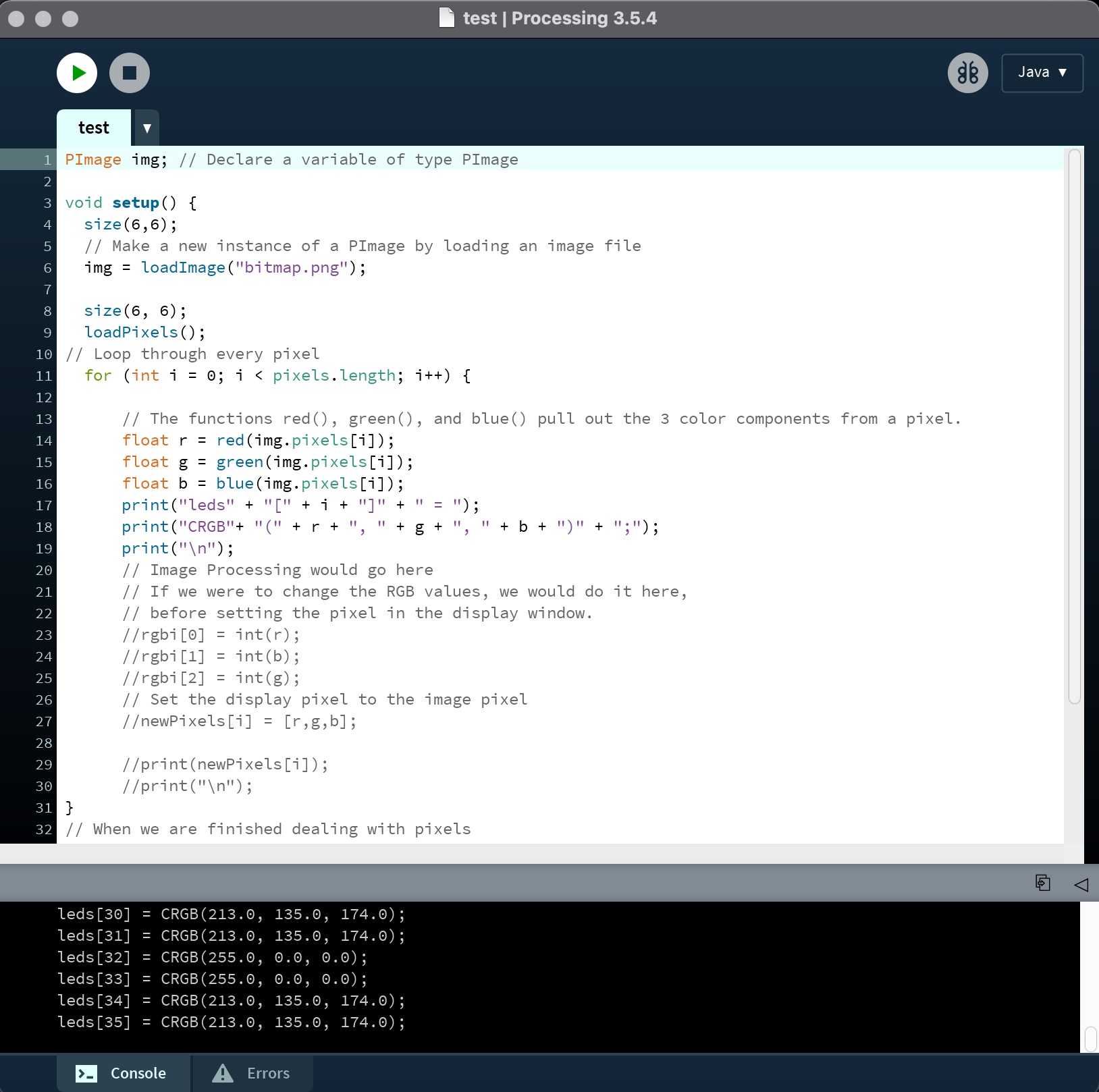
I used a few lines of code in processing to display the image, and added a for loop to go through each of the pixel and extract the RGB value. Calvin helped me a lot in learning some useful programming commends. Eventually, I set up the code in processing so that eveytime I run it, it would give me an list of all the rgb values for each of the pixel.
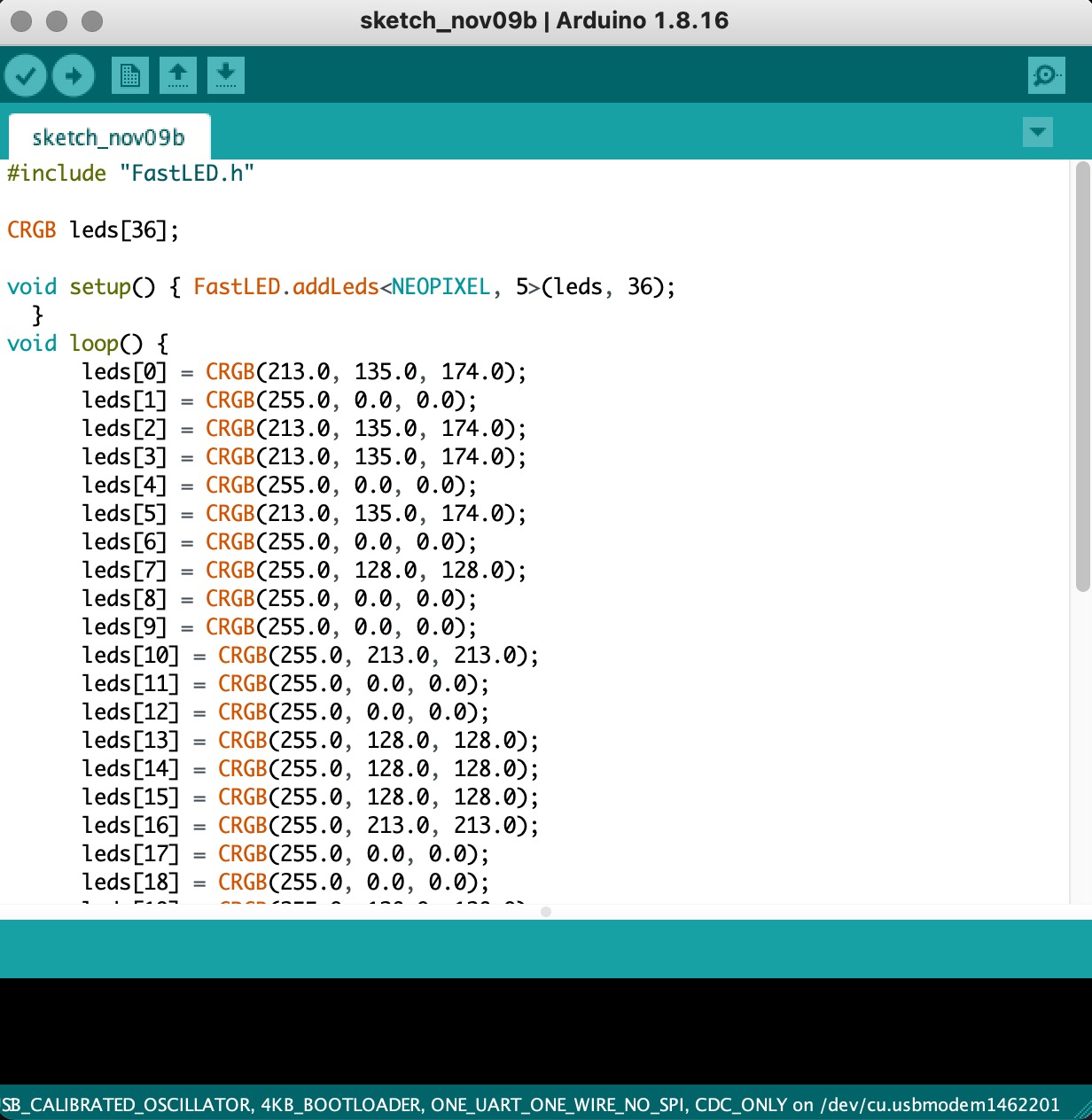
With this information, I can copy and paste into arduino and upload these informations to the board! The process is not very user friendly for now, but I will try to ease the process. Calvin suggested me to make it live, which allow user to draw and see their art being displayed in real time. I will have to learn the communication between arduino and processing.
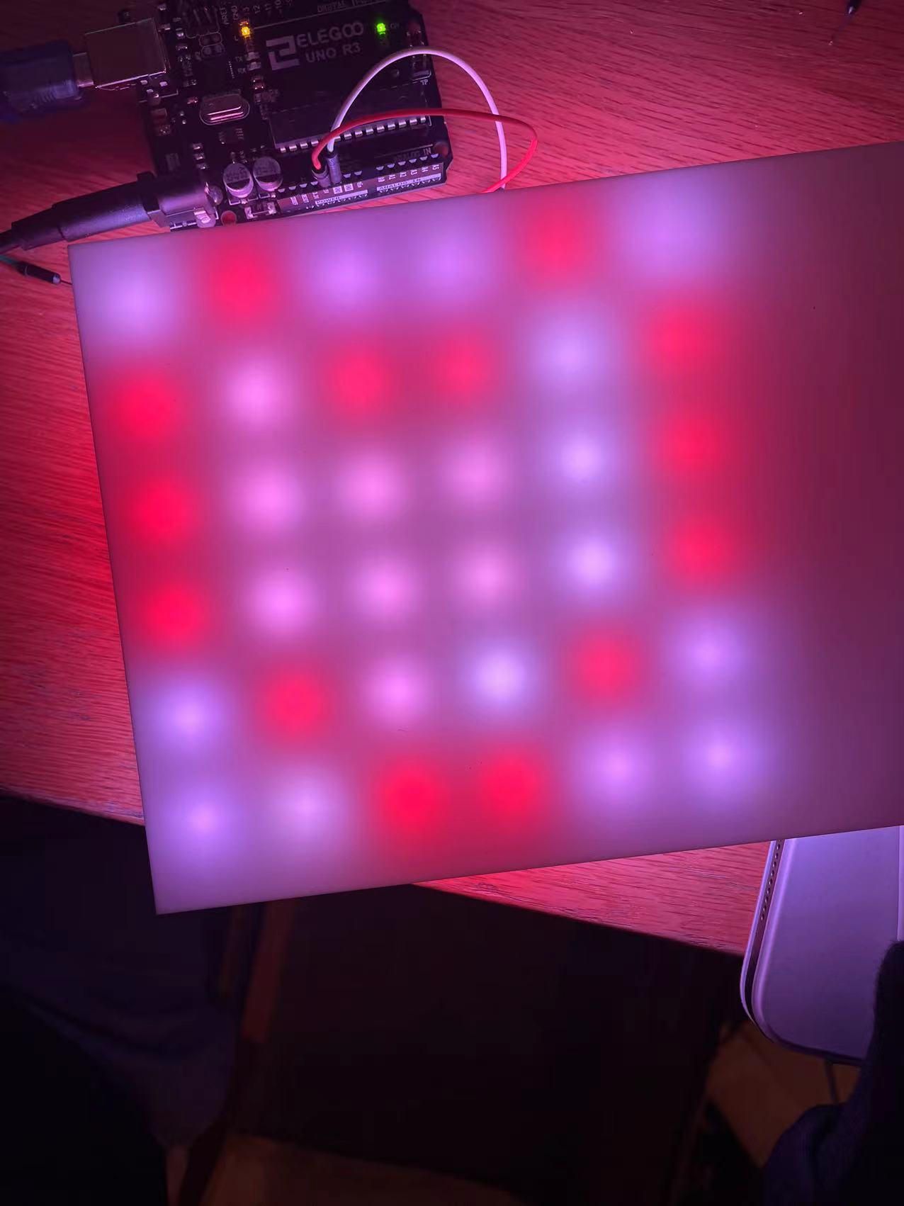
This is how it looks when projecting onto the frame! I really like the result, some of the colors are slightly off but overall it captures the details pretty well! I will also try to program some patterns with movement and store that in the board.
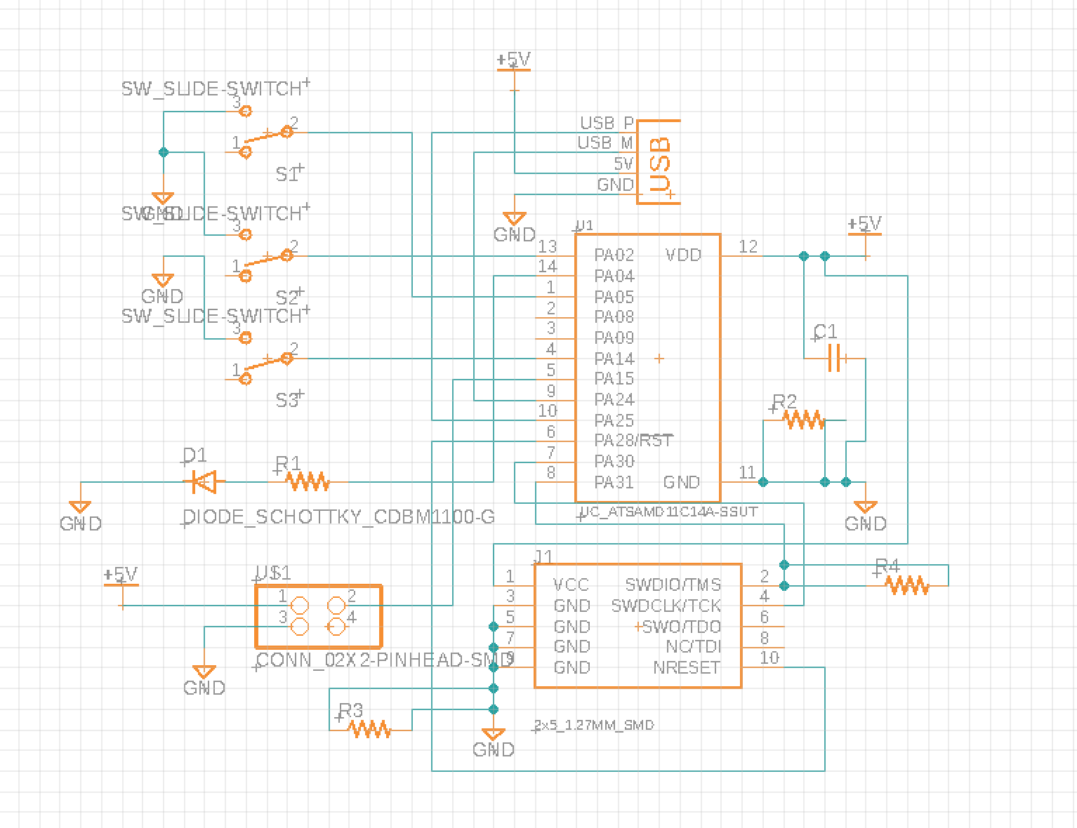
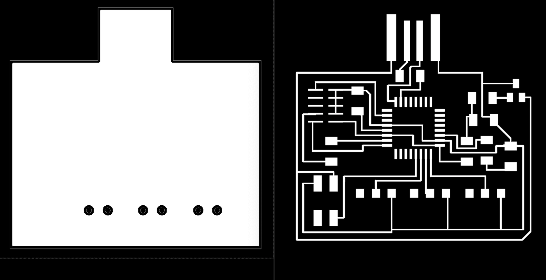
I realized that I have been working with the arduino uno board for the past experiments, so I decided to make my own board. Here is a scheme of the my potential final board! I added three switches to store some default patterns in there, and added a four pin connector to connect the groun, power, and led pin to the microcontroller. The overall board is pretty simple, because the input device in my computer, so I can also use the usb connector.
Here are the tracings for the final board. I will make and stuff it this week and try to program the board with this new board.
//
11-16: Fabricate the controller board
For the past week, I have been struggling to design the pcb board for my final project. More details can be found in week9.
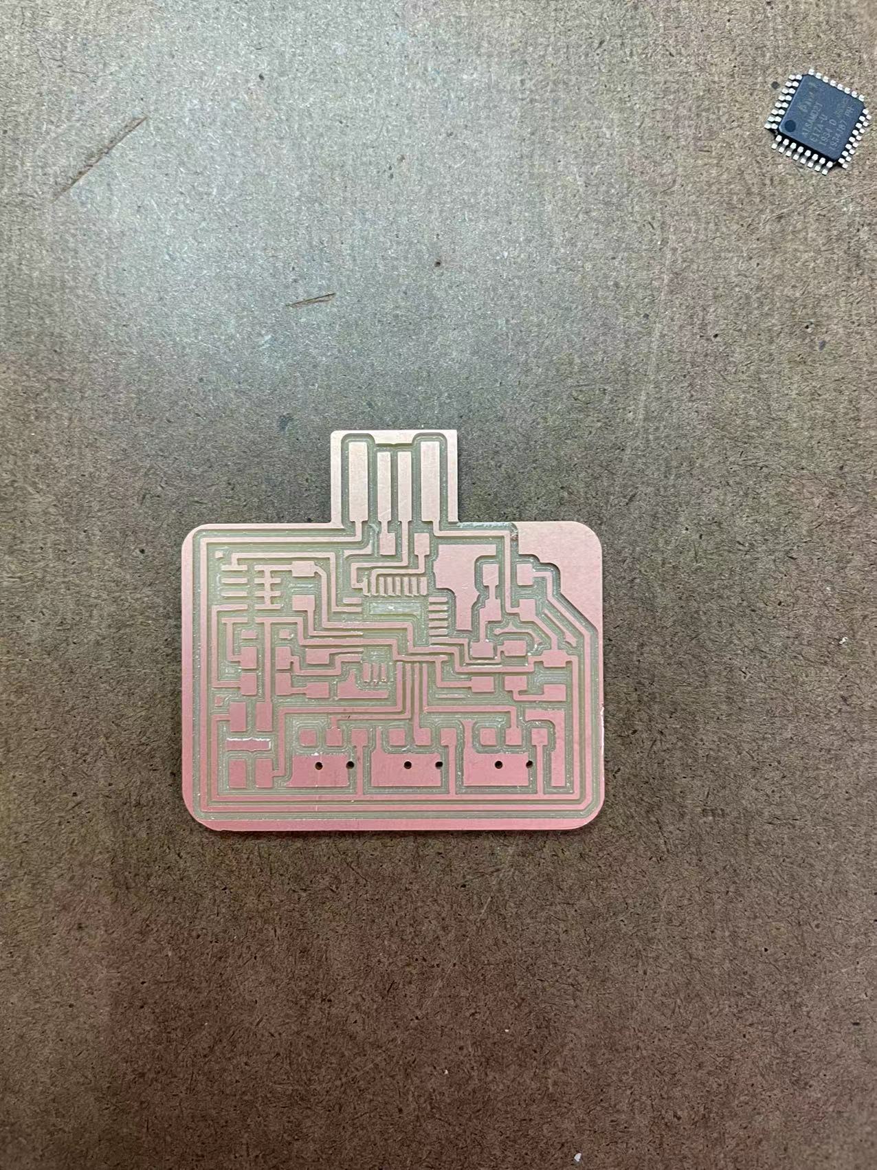
Here are the first two boards. I was able to successfully bootload the left one but the adafruit library was not capatible with D11C I had to change to D21E. The right board did not include a voltage regulator which means the microcontroller can't be bootloaded succesfully. I will have to make a new one for the prototype.
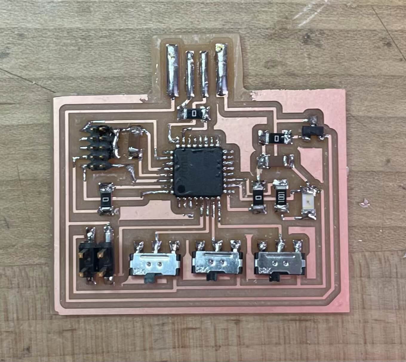
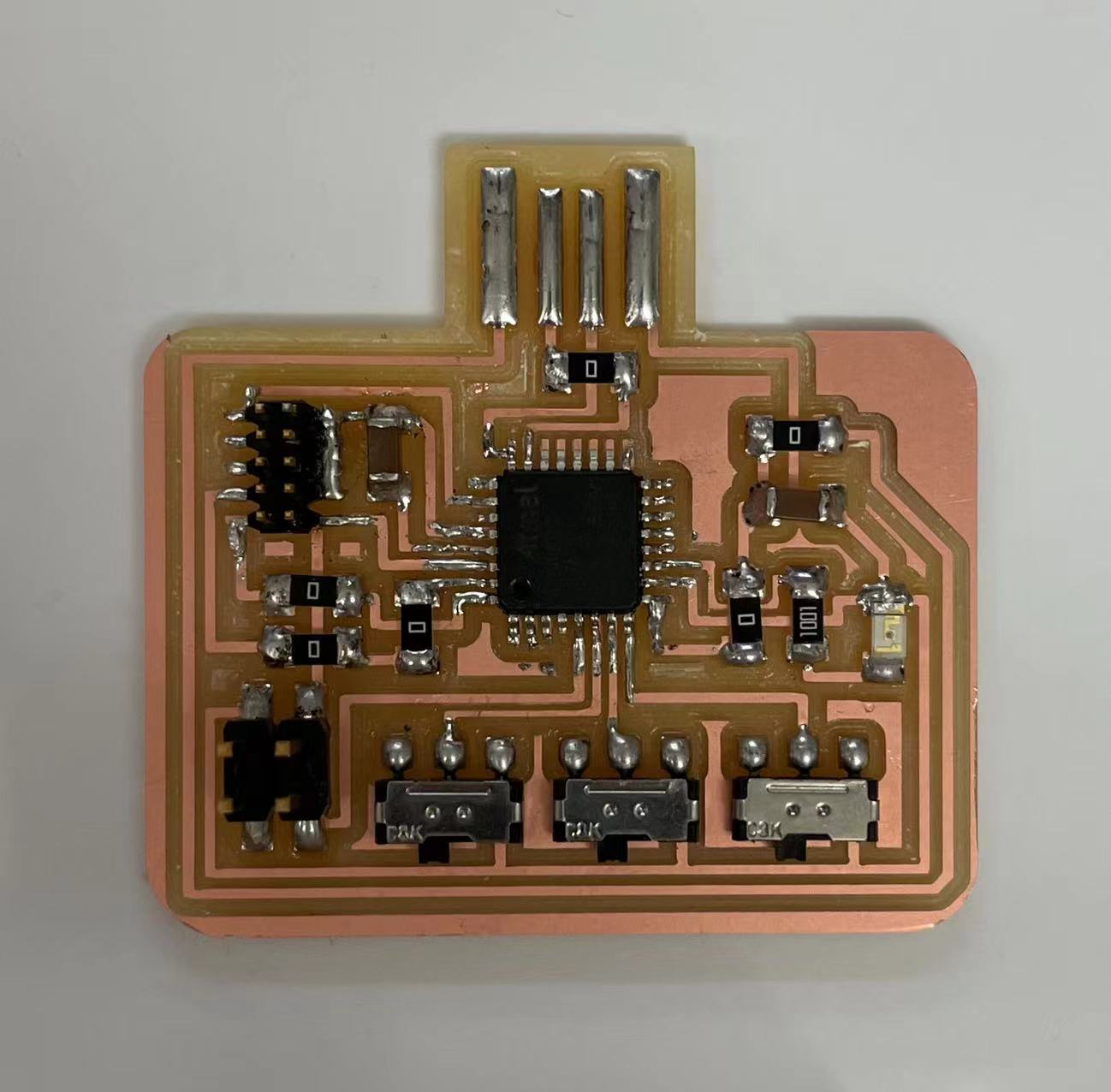
I made a new board and fixed the problems with the voltage regulator and microcontroller. More details can be found in week9. This new board consists a D21E microcontroller, 3 slide switches, some pin headers, resistors, and capacitors.
It worked! I am really excited about how this turned out. I will probably make some new boards just as backups because the connection between the board and the computer is still unstable.
04 Final Documentation
//
11-14: Computer controlled machining
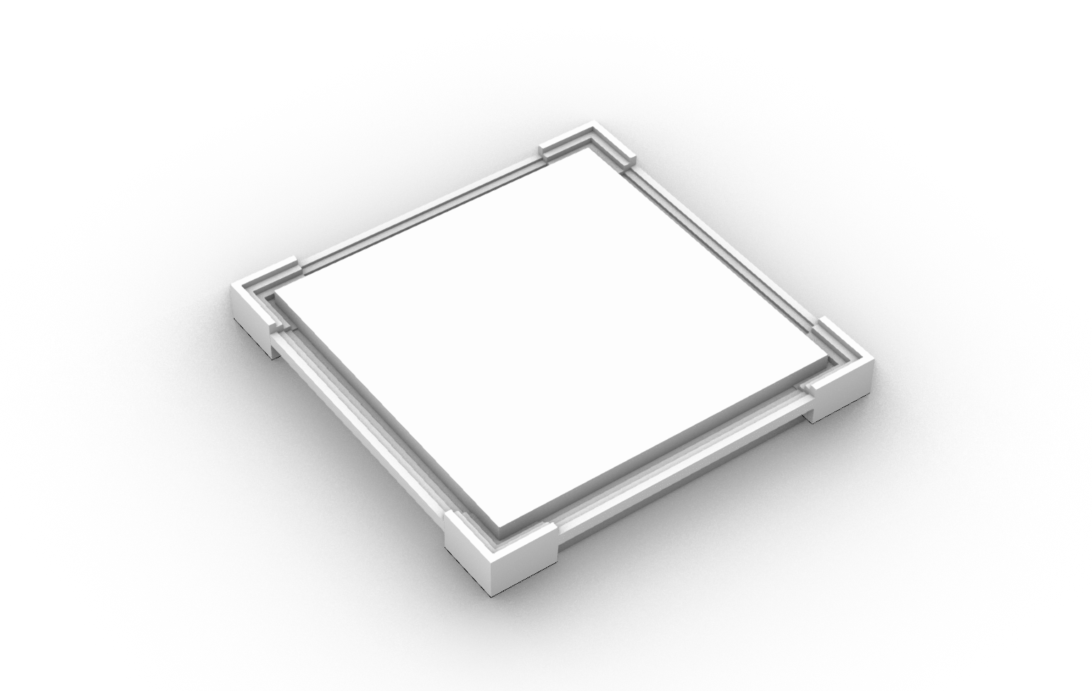
I started fabricating the final project this week. While waiting for the material to arrive, I re-modeled the project and draw all of the shapes that I wanted to cut on the laser cutter.
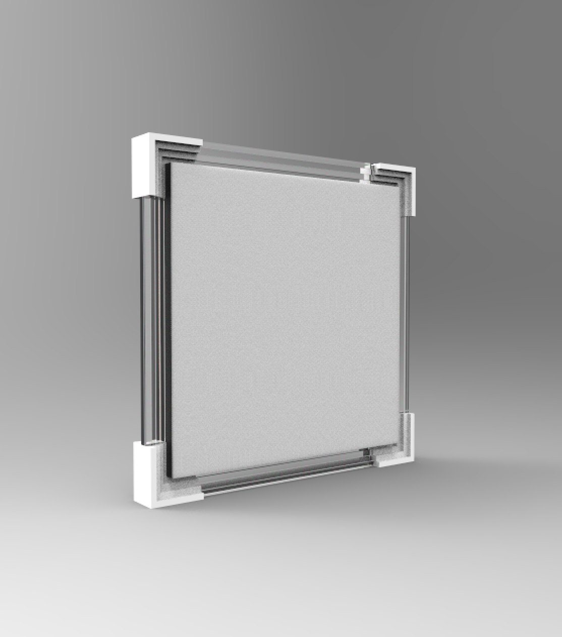
I rendered this in keyshot to get as close to what it will look like in real life. I will use addition fabrication method for the corners, and subtractive fabrication method for all of the structural supports. The fram is approximately 12" by 12".
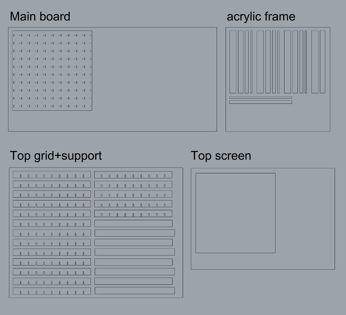
Here is how I organized pieces in rhino. I draw a large rectangular box that is the same size as the material so that I can organize parts in them. I will start cutting them this Friday.
//
11-16: Fabrication
I used the template from earlier this week and fabricated all of the neccessary parts for the final project. However, the laser cutter was acting a little weird this week and wouldn't actually cut out the accuracte size. I might need to ask Shah and change the pulse setting on the cutter.
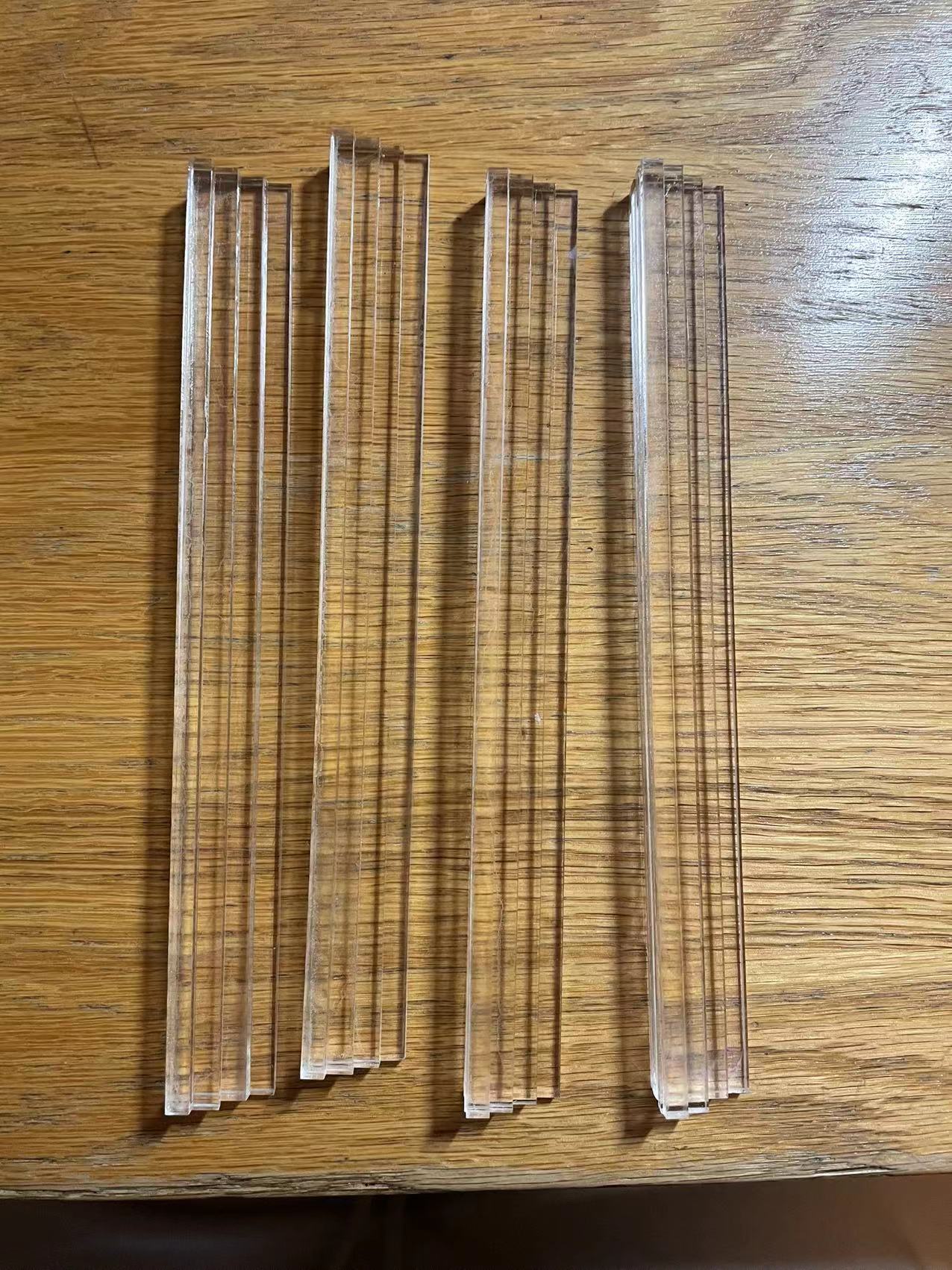
Here are the parts! I used chipboards as the main structural material and white+clear acrylic as the add-on material. I 3D printed the corners in white PLA.
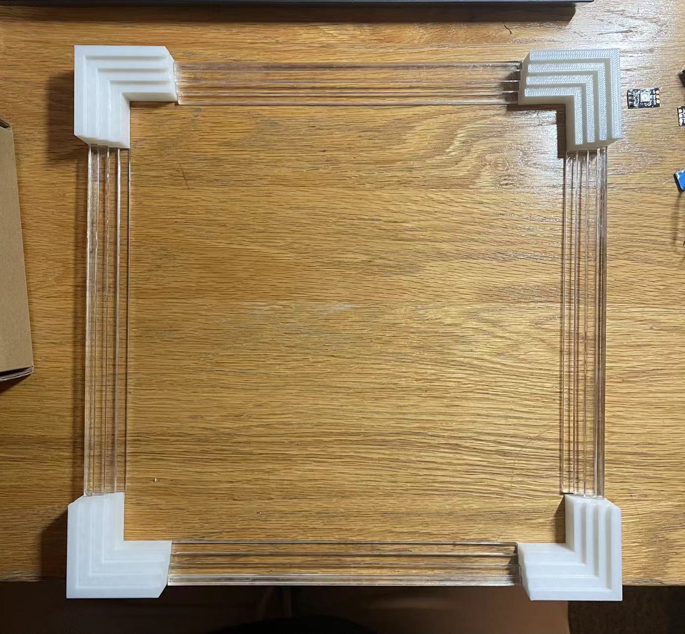
This is how it looks when putting together! The frame looks exactly what I wanted. However, the acrylic cement kinda left some marks on the clear acrylic which makes it gloomy. I will continue next week and start fabricating the main board with LEDs on them.
//
11-26: Fabrication Continued
I started on the hardware wiring part this week. In total, I had to soldered 654 joints, which took me three days to complete.
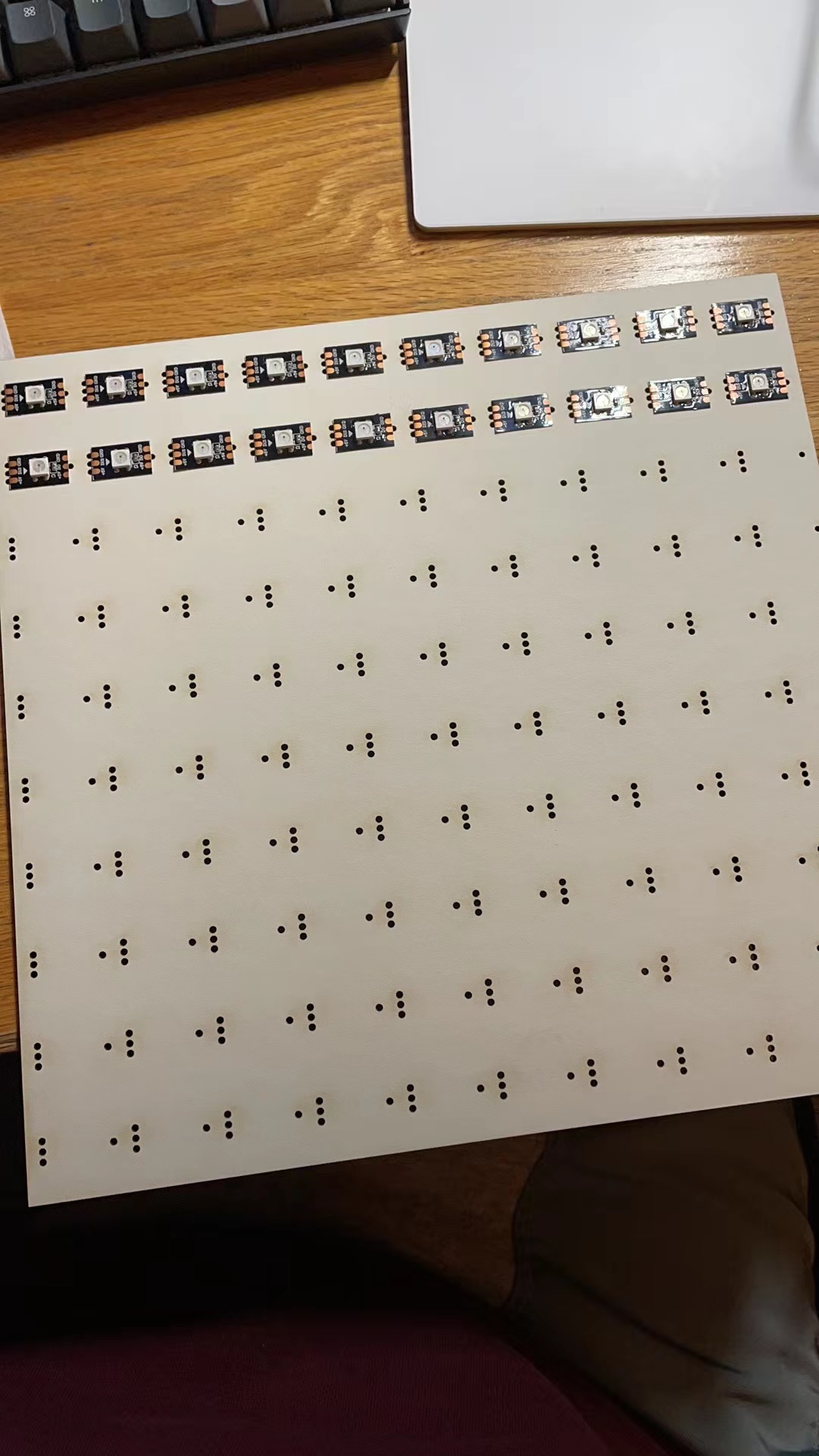
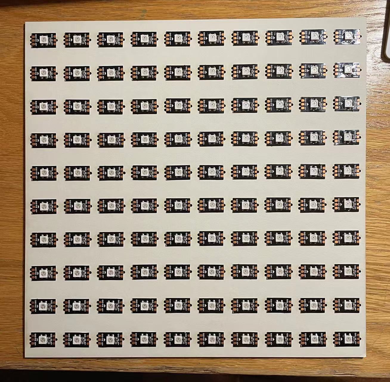
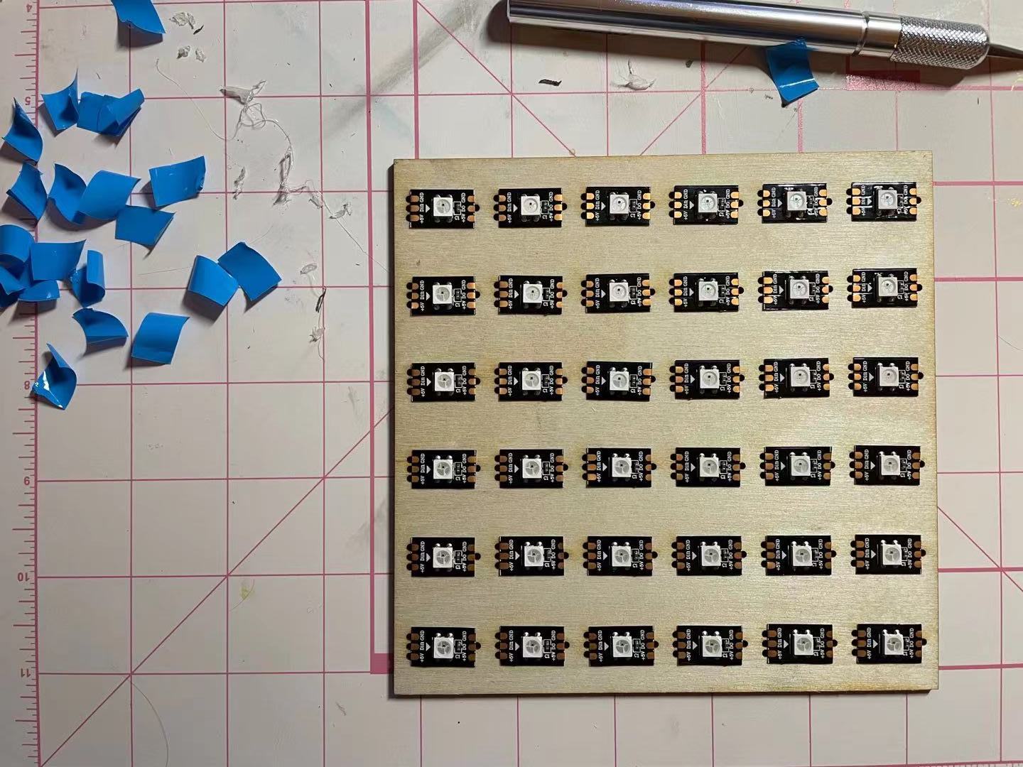
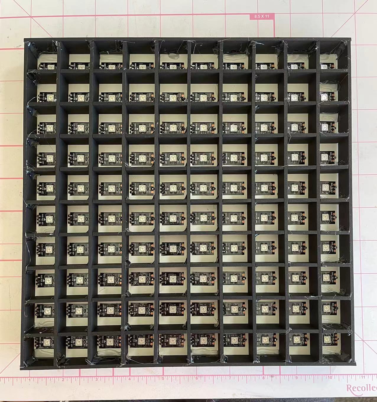
I started with taping all of the LEDs onto the board. It's nice that the ws2812 LEDs have glue on the back so that I can just peel off and tape them. The right image is the complete look, there are 100 pixels in total.

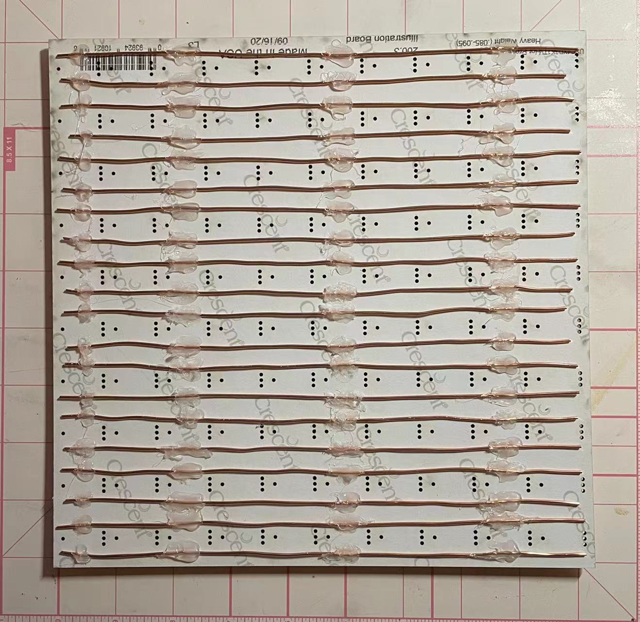
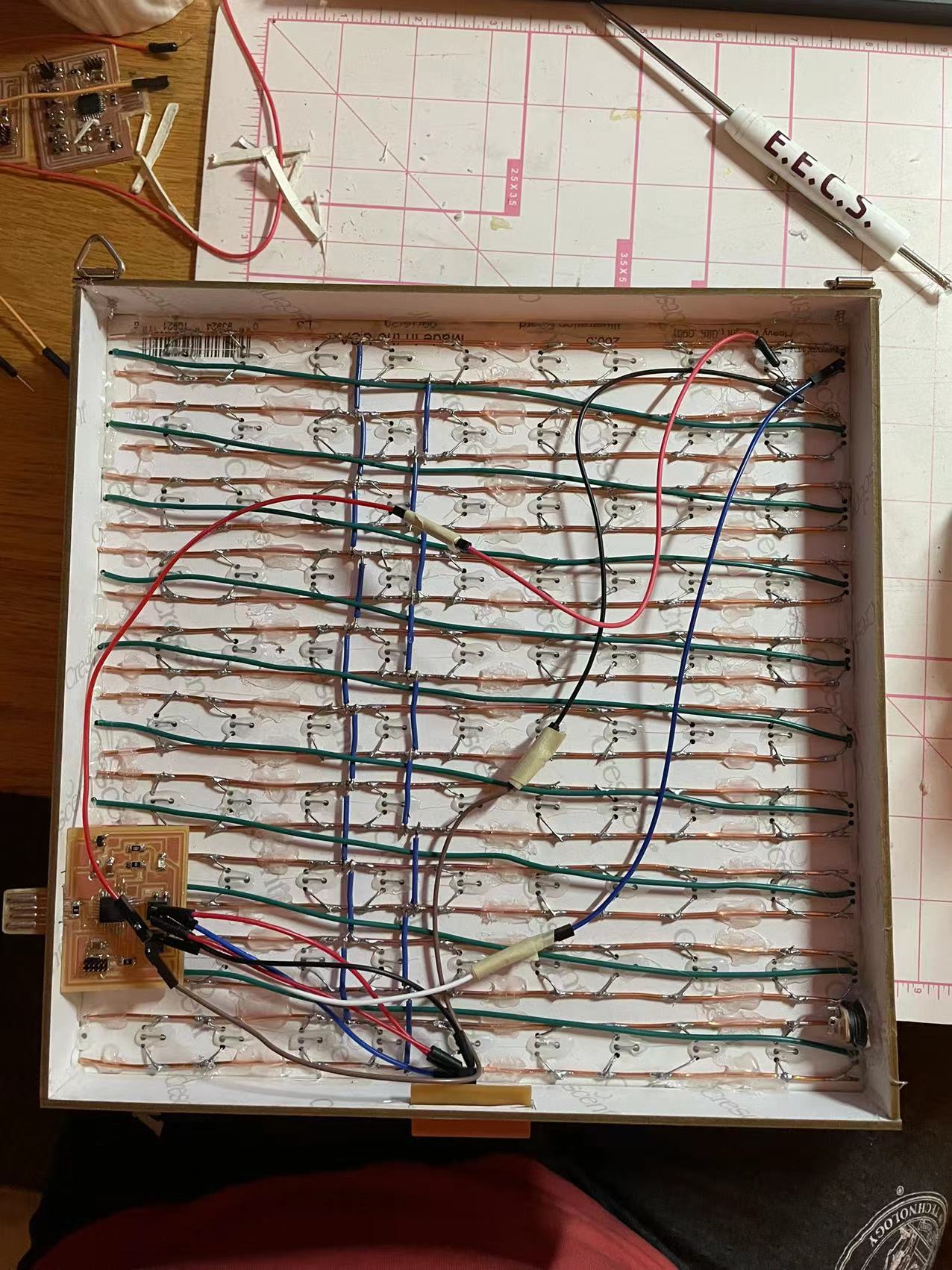
The next step is to wire up the LEDs. I need to connect all of the ground and power together respectively, so I started laying out copper wires on the back of the board. These orange wires will be mainly used for the gound and power. Each of the indvidual pins will connect though the middle holes on the board.
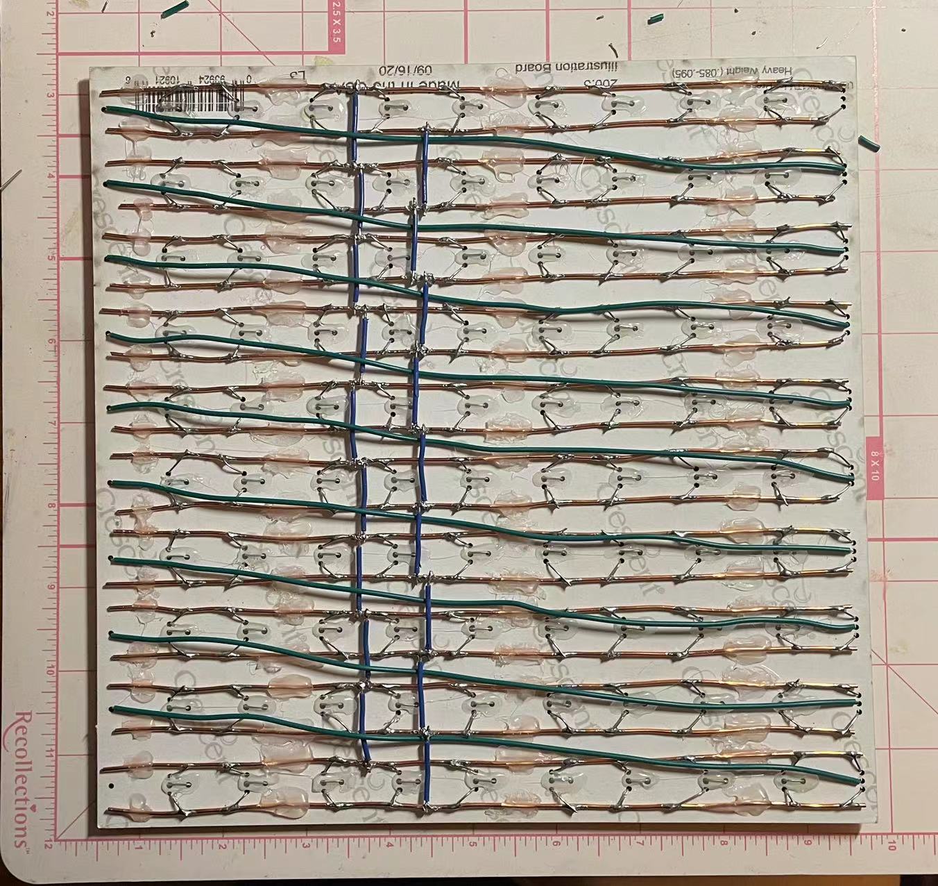
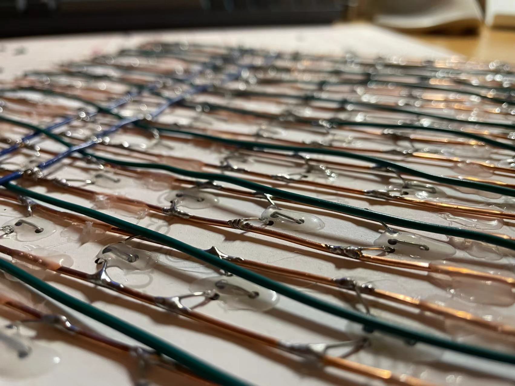
This is the finalized version! I connected the ground and power through blue insulated wires vertically accross the board and added long green wires to make the LED light up in "S" shape just like how pixels are recognized in processing. (More detail of pixel wiring can be found in week11). For next upcomming week, I will finish up the hardware part and start on the pcb board fabrication. There are still a lot to be done and I am quite nervous about how the PCB board will turn out.
//
12-01,02: Final PCB board making
The board is now completed! I decided to test the board and make a new set of final pcb boards.
I tested the board row by row to check the connections of each LEDs. However, I found two LEDs that got stucked and wouldn't pass down any information to the next one.
I tried to troubleshoot the problem by replacing the LEDs but they still wouldn't follow the code. I then went to Anthony's office hour to figure out where the problem is. It turns out that I only needed resolder three joints. For the soldering, I used a portable soldering iron which is not ideal and can cause a lot of connections problems... Anyway, thanks to Anthony, the problem is resolved and all of the LEDs light up correctly!
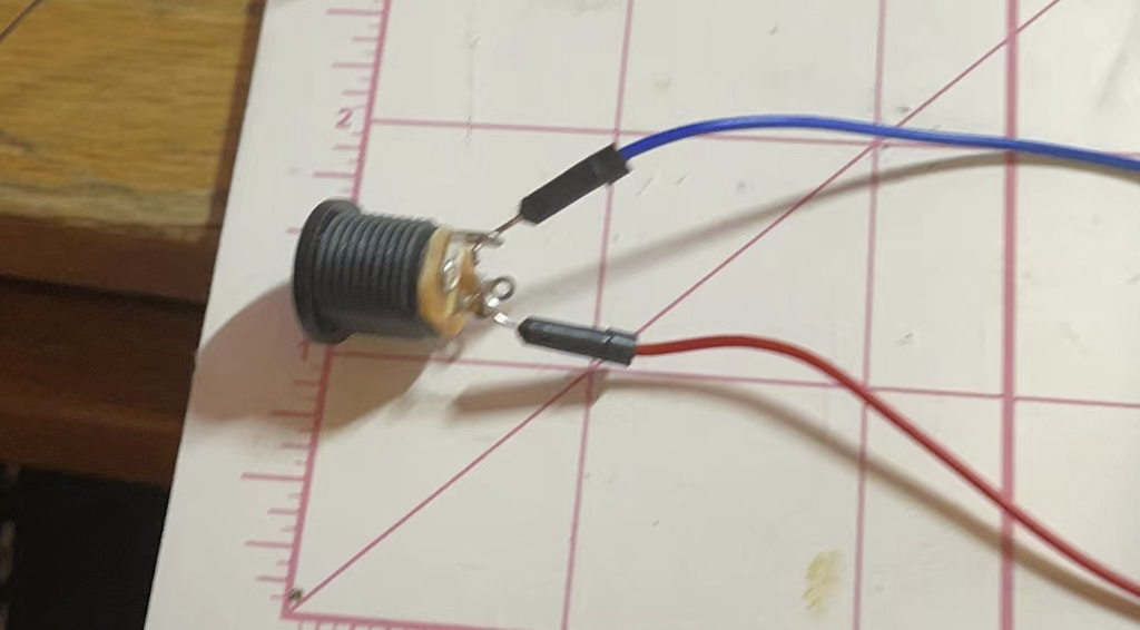
Another problem arised along the way is that the power provided from the computer is not enough for 100 pixels. I will need to connect this power socket to the board so that I can connect a external power supply to the board.
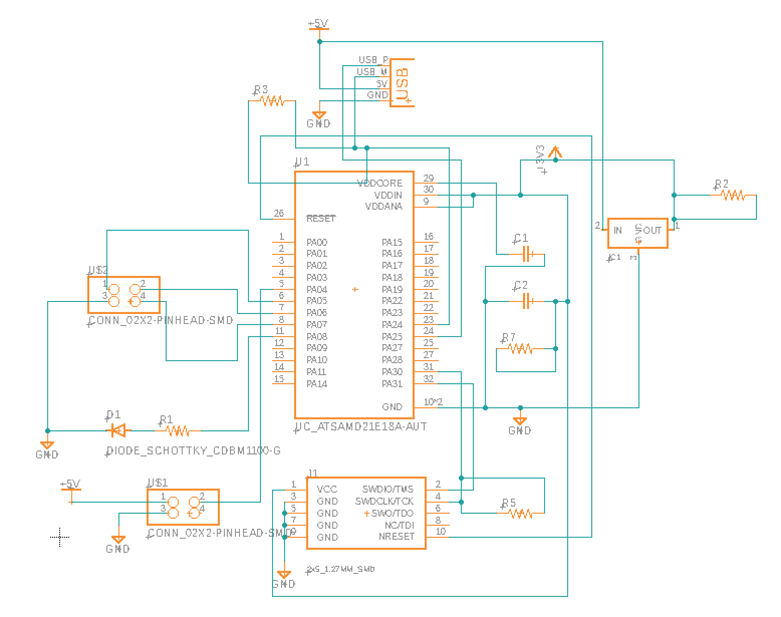

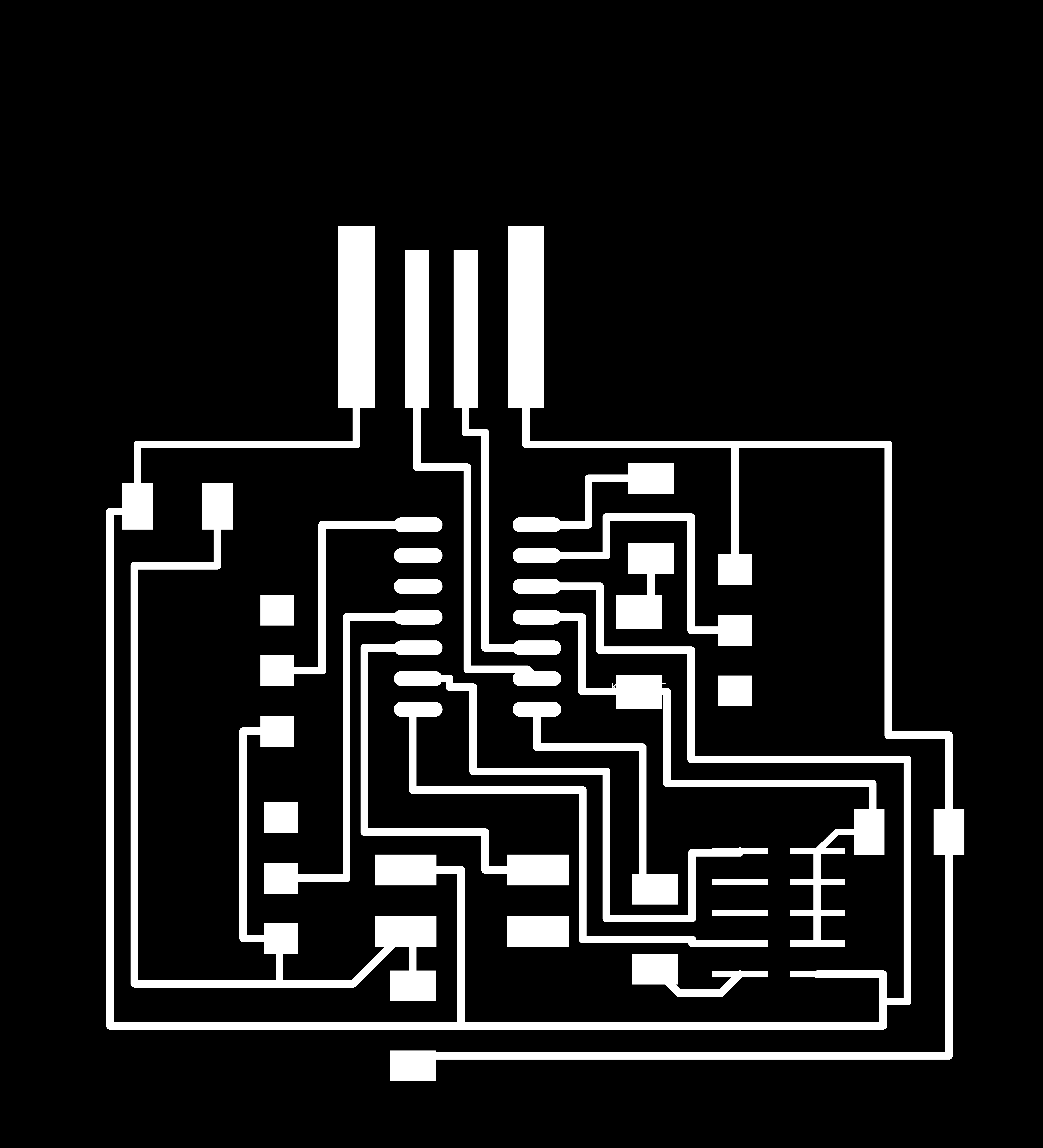
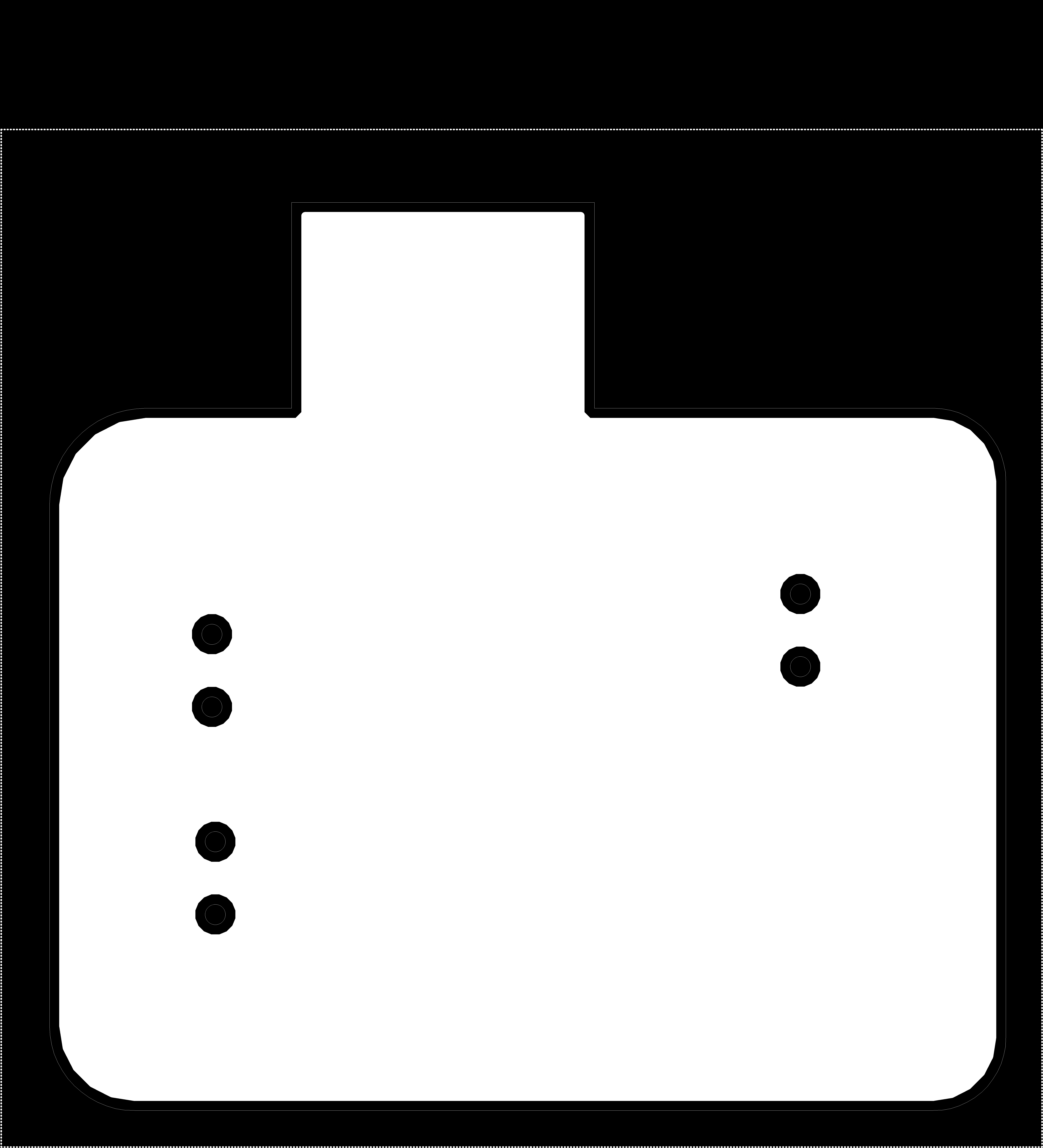
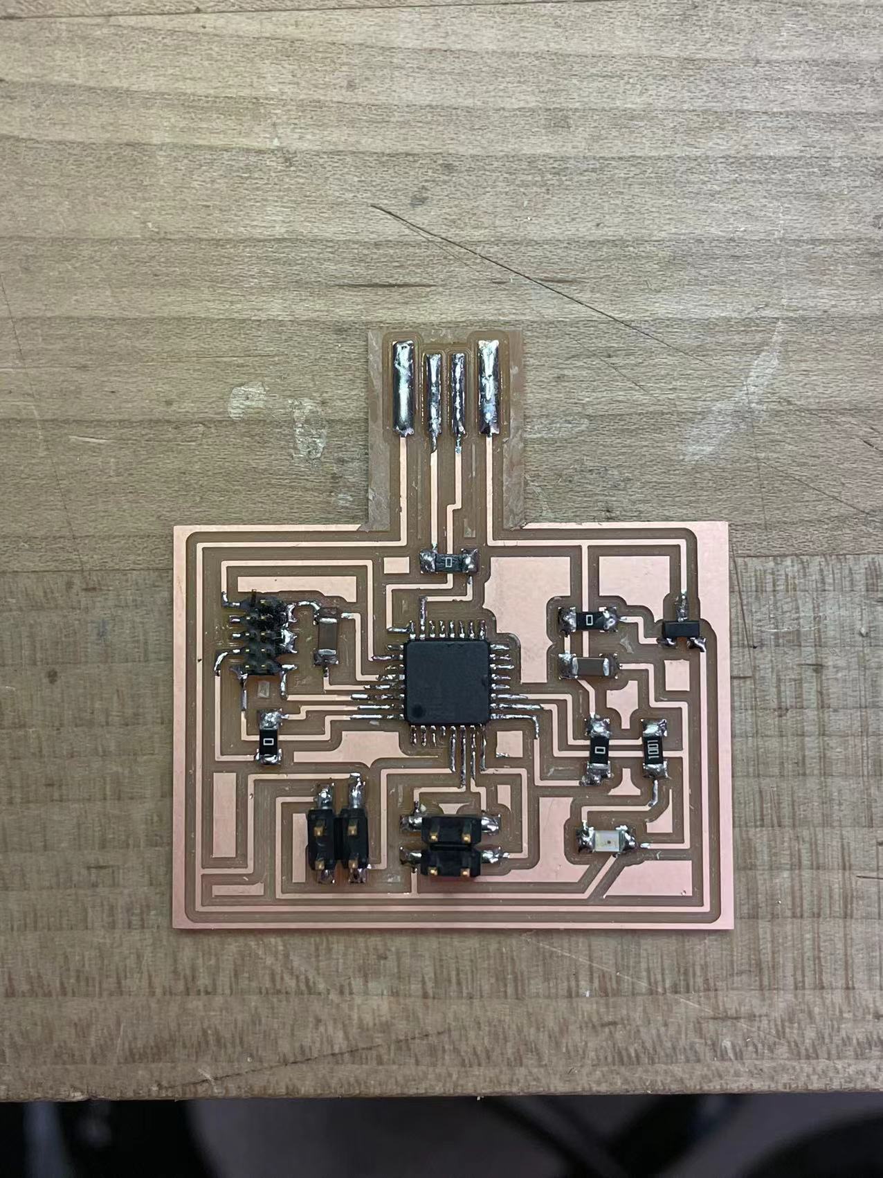
Now that the board is working perfectly, I need to remake a pcb board to program my hardware. This one is not much different from the board I made during the output week. I basically just wanted to separate the switches(input) from the main board. The above image is the scheme and routing for the main board. I also made the neck a bit longer so that the usb head can stick out for programming in future.
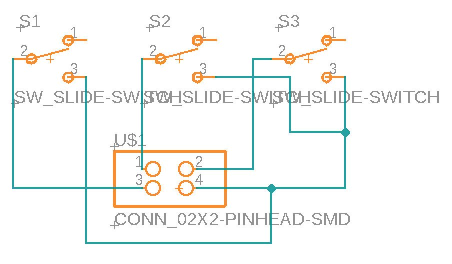
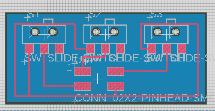
These are the schemes for the input board which are also going to be sticking out from the side of the board. The switches are ther triggers to switch image that will be displayed on the board.
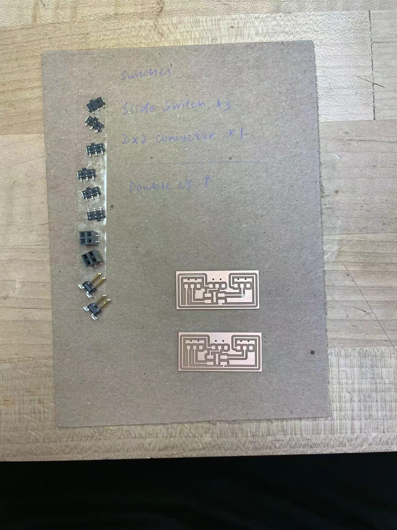
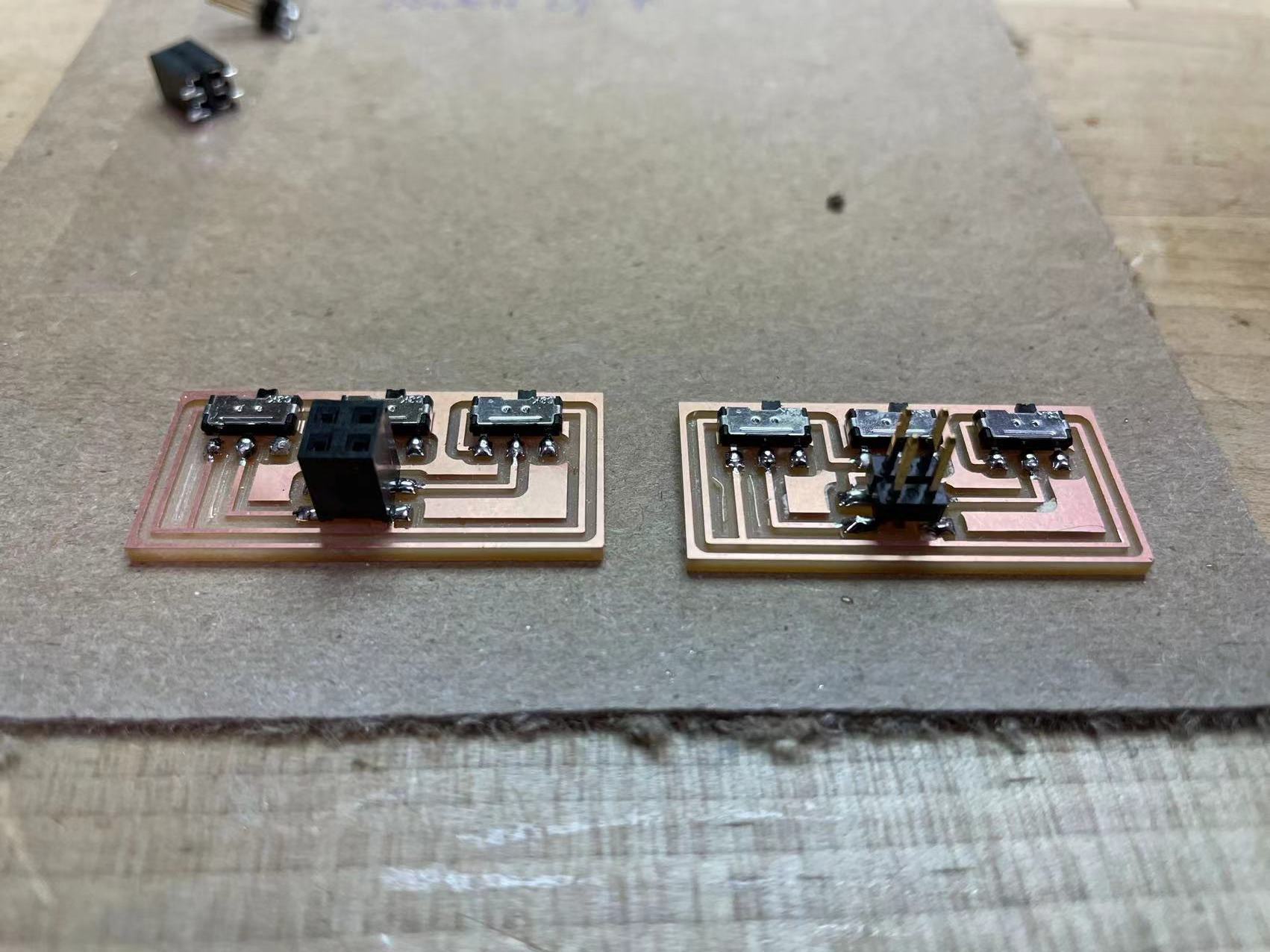
Here are the input boards. I made two just in case any of them doesn't work. I also soldered them with different kinds of receiver to test which one will fit in the back of the board better.
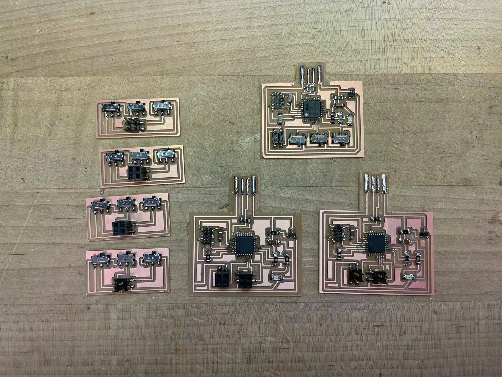
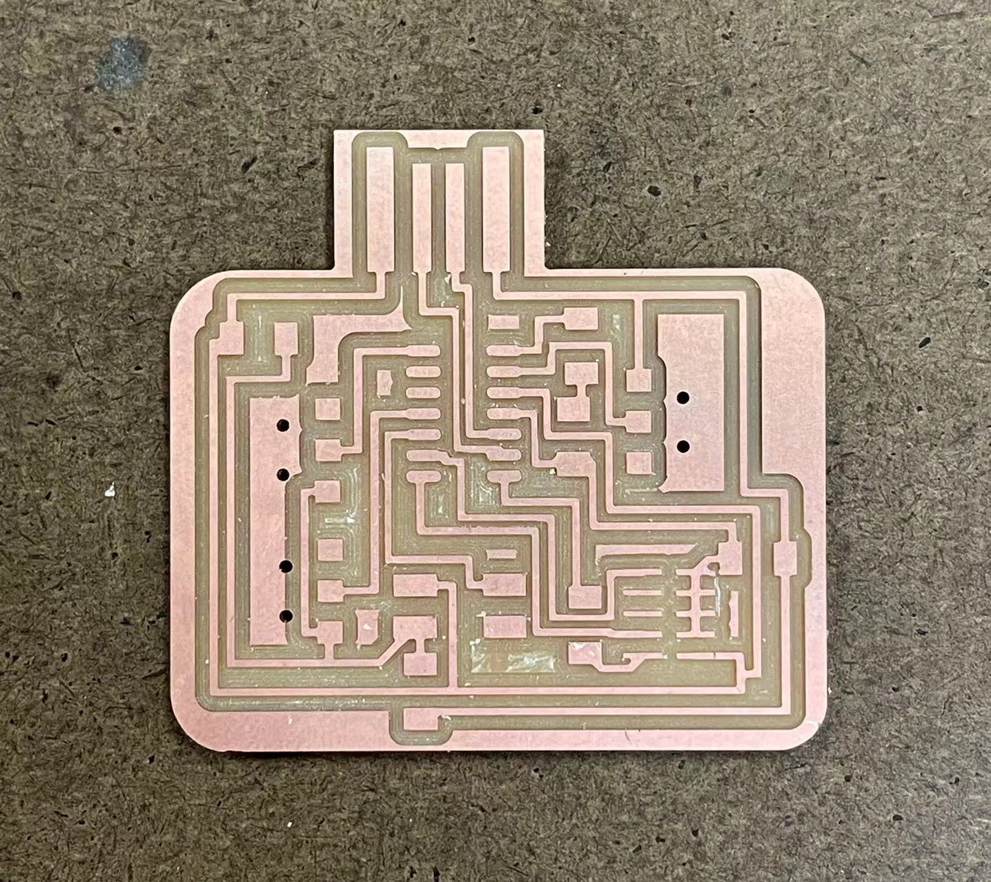
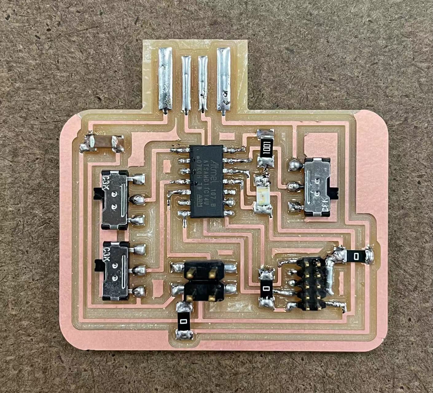
The left image indicates the finished version of the main board. The right image shows all of the board I made in the past week. Luckily, I was able to successfully bootload the board and get it ready to program.
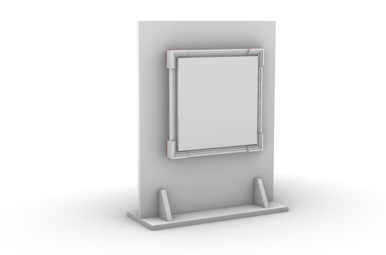
Now that I have all the needed material and functional boards, I can start finalize the model this week. I was also thinking the way I can present my project during the finals week. Since this is a digital canvas frame, it should be hanged up onto a wall. So I decided to cut a standing rack using the unsrud machine to hang up the frame. The image indicates how it should look like as a finalized product.
//
12-04,05: Final model construction
Having all the components I need for the final model, I can't wait to get started with the final construction. I started off with the programming part. Essentially, the frame can display and store three images on the micro-controller. When the user flip one of the switches, the display should change to the corresponding image. From the interfacing week, I designed a workflow to pixelate image and find the pixel information to upload on the board. I used the same process for the final model and analized three images.


These are the three images I used to upload to processing and arduino. They look extremely blurry because they are all 10 by 10 pixel images. I drew the first and third one in inkspace using a 10by10 px canvas and image processed the second one using the scripte from week11.
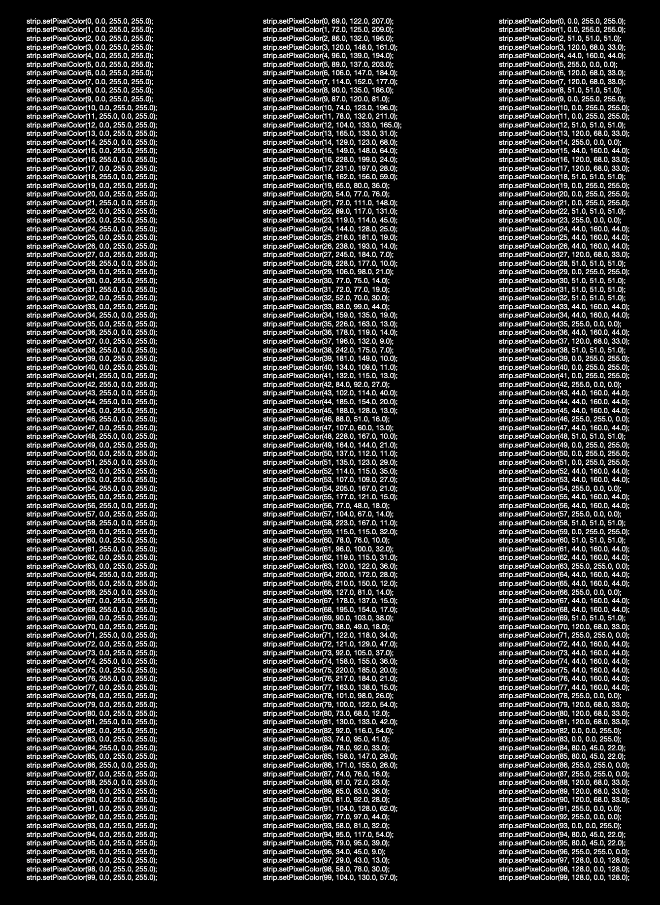
These are the data returned by processing (a clear code can be accessed from the file linked down below). Each of the image returns a array of 100 lines that can be directly copy paste to the arduino program.
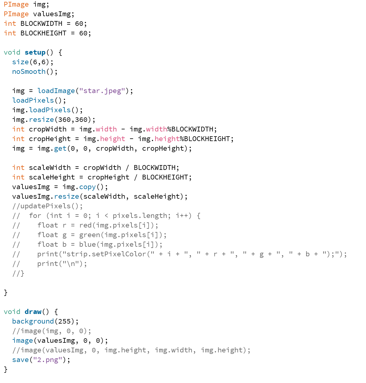
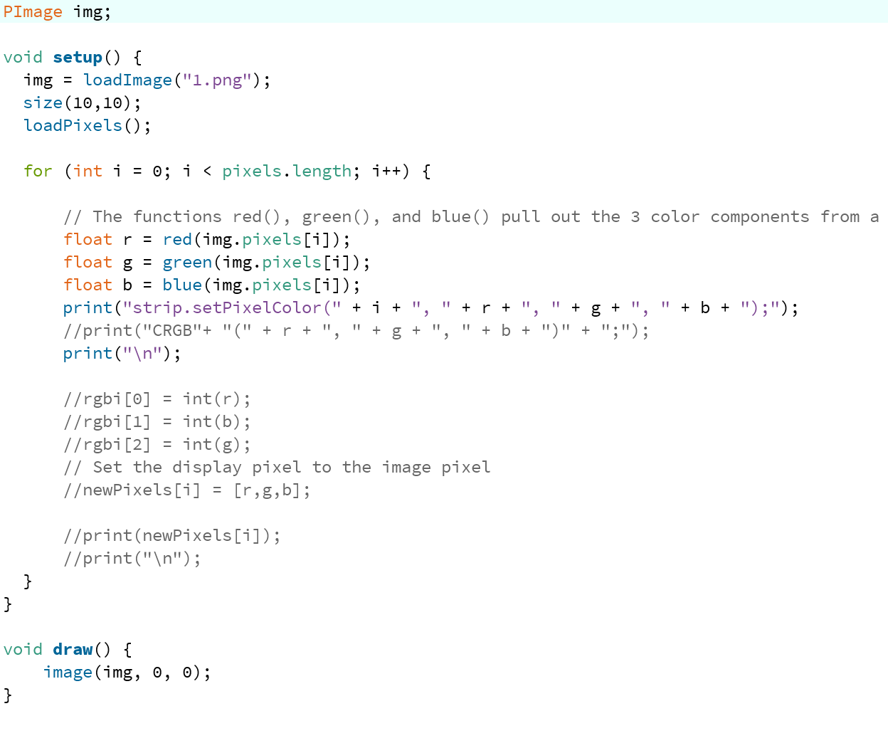
These are the code I used for the image processing part. More detailed description of how I did this can be found in week11.
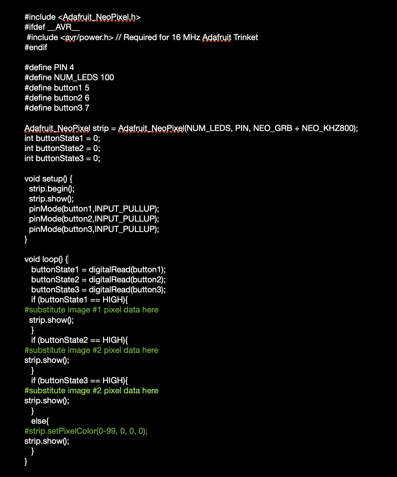
This is the final arduino code used to upload the images. Basically it uses if and else statement to enable different input to the display. If none of the switch is open, the display would just turn off.
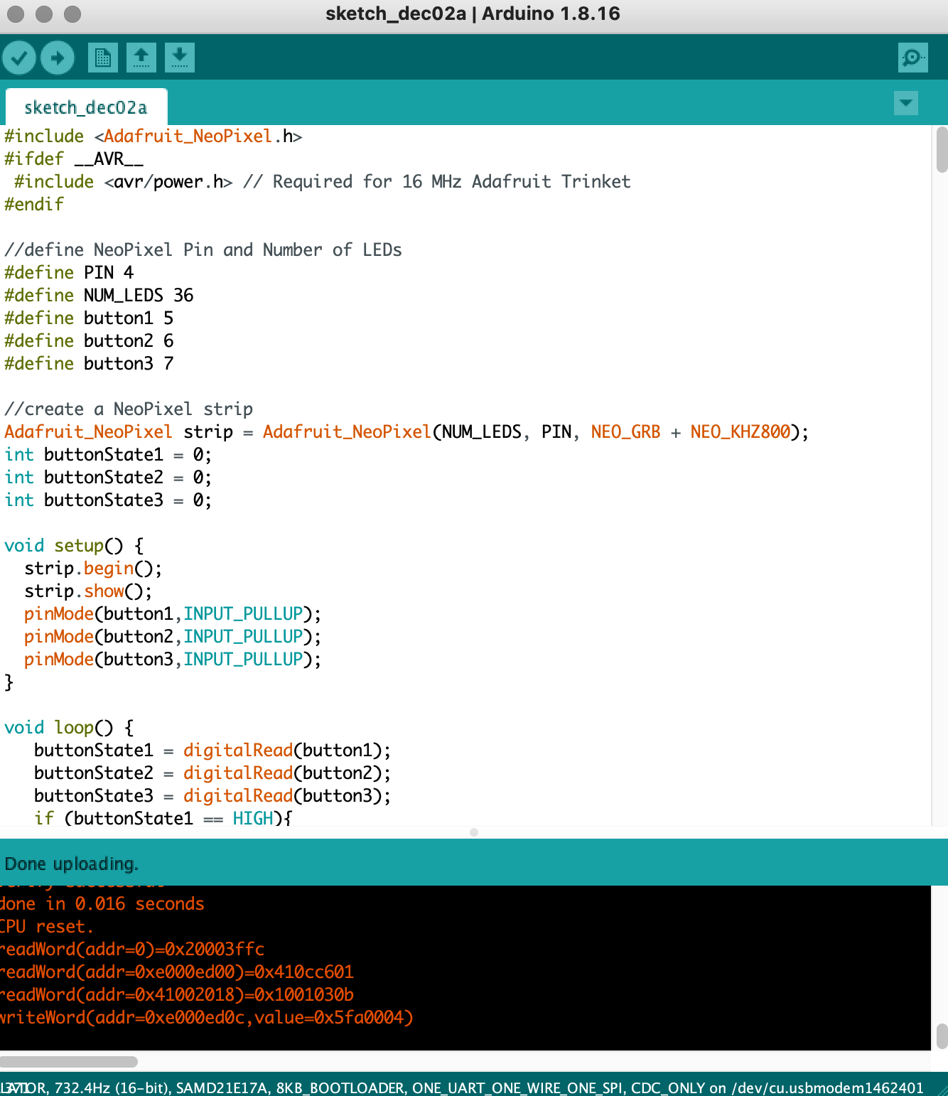
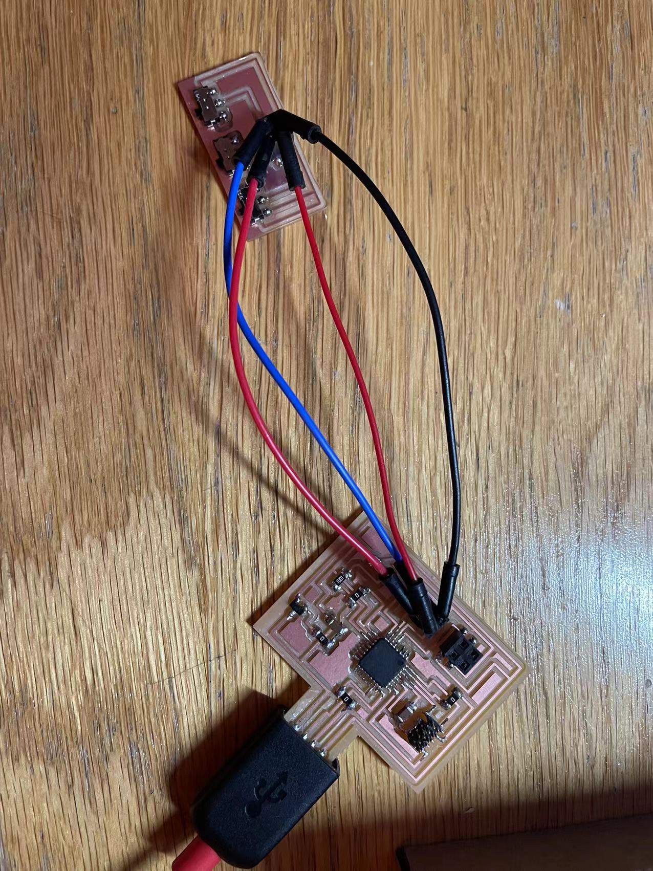
Luckily, my computer recognized the board and it uploaded perfectly fine! Now that I have a functional pcb board, it's time to check if it would do the thing on the actual hardware. The right image is the board set up for the program.
I first tested the program on the protytpe and it works out really nicely. When I switch the button the display can immidiately switch to another corresponding image.
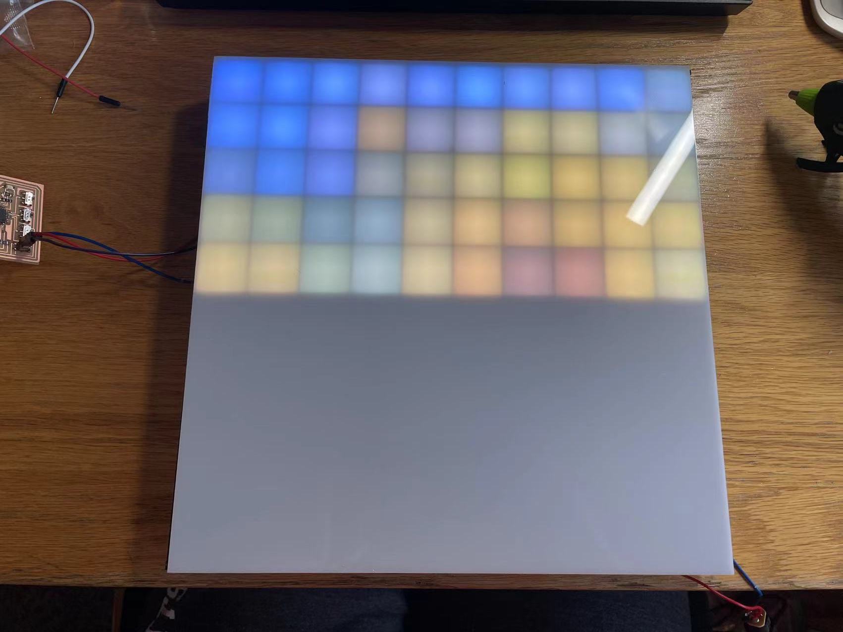
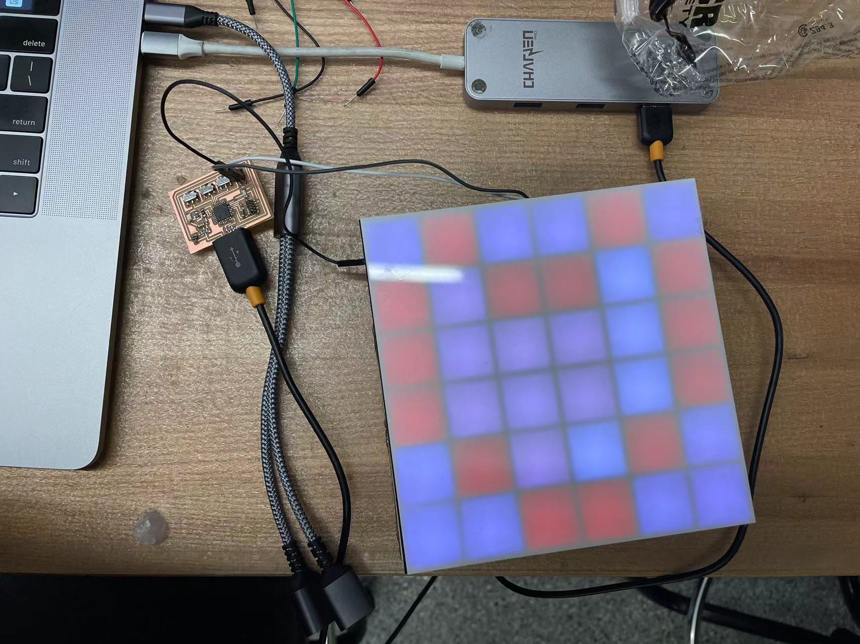
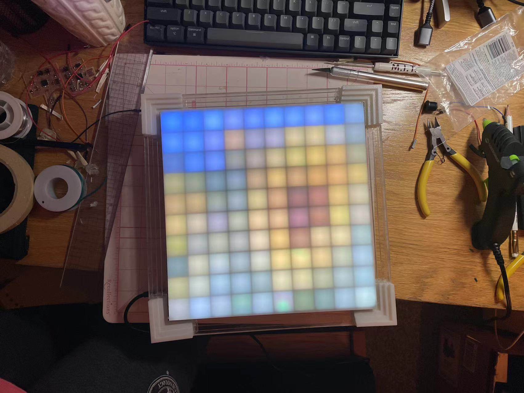
Now I tested the program on the actual model. I uploaded 50 LEDs first just to check if the color display is accurate. I then connect the board to a external power to display full pixels. Hoooray! It works! The colors look pretty accurate and the brightness is good too. The thin white acrylic really did its job on disfusing the lights.
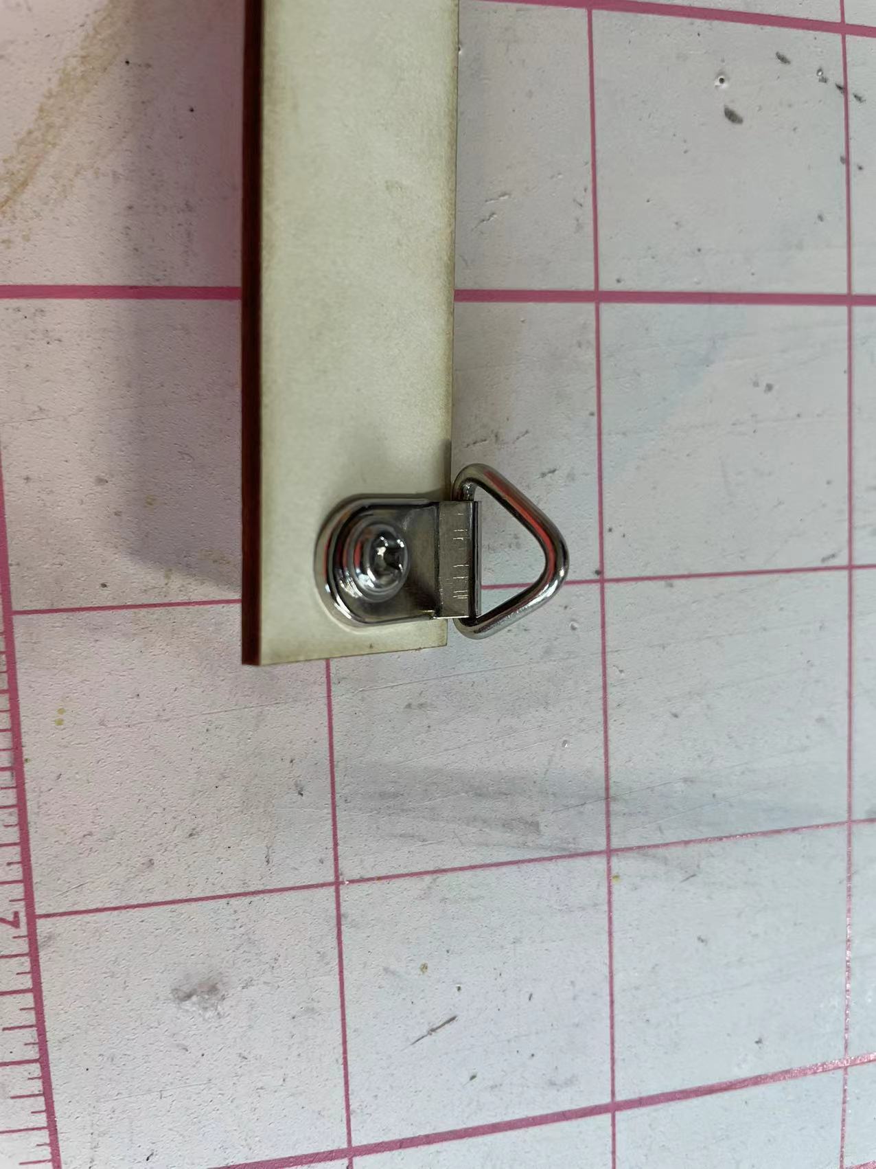
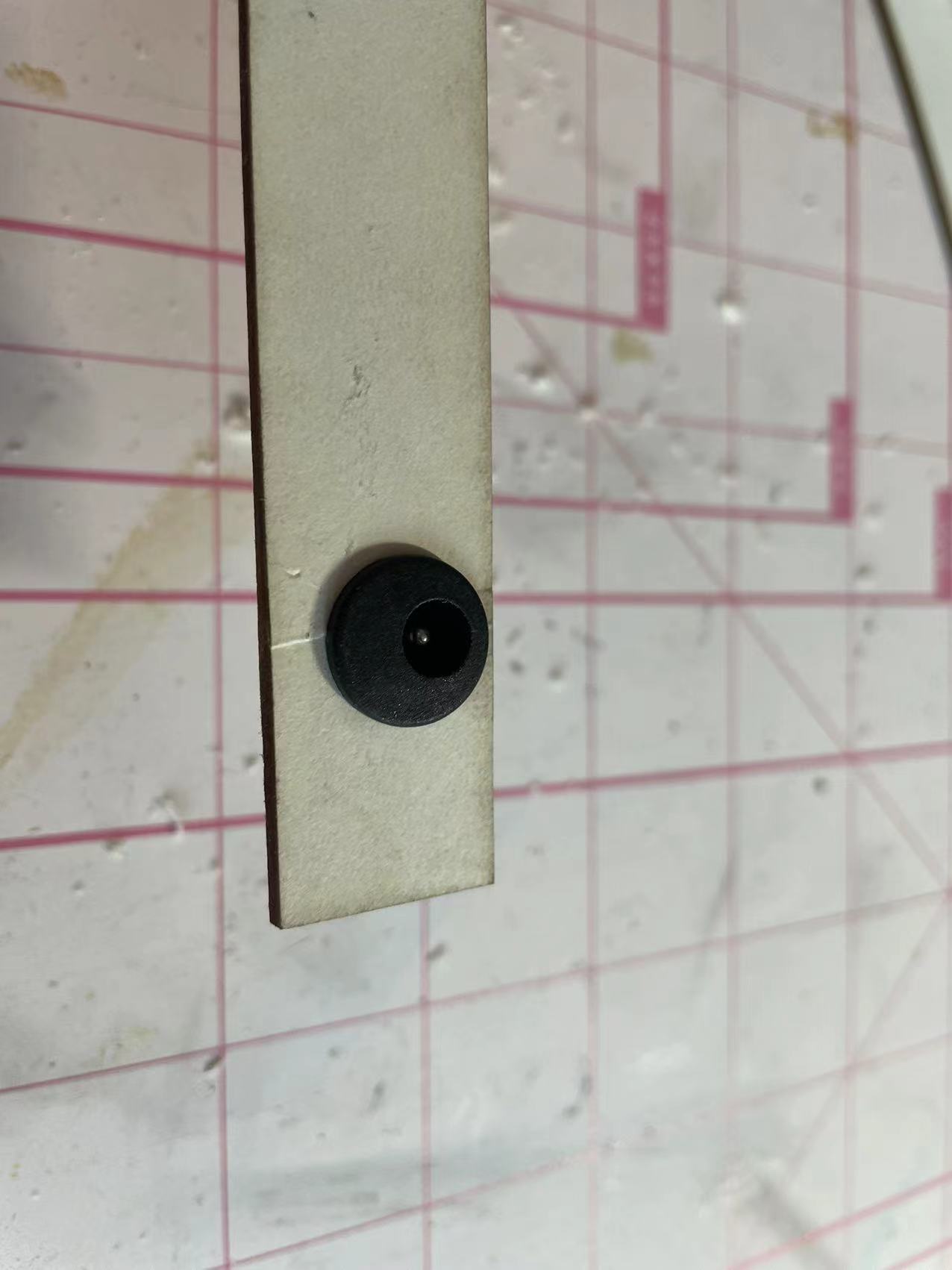
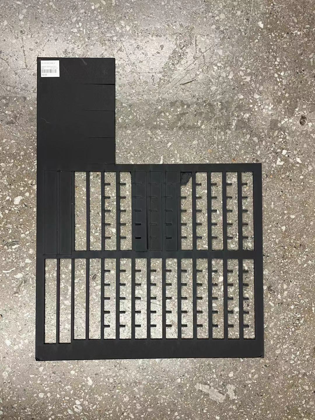
Now I can finally start the putting up the whole model. I started with the black grid that was made by lasercutting. I also added the socket and some hanger on the back stripe of the board.
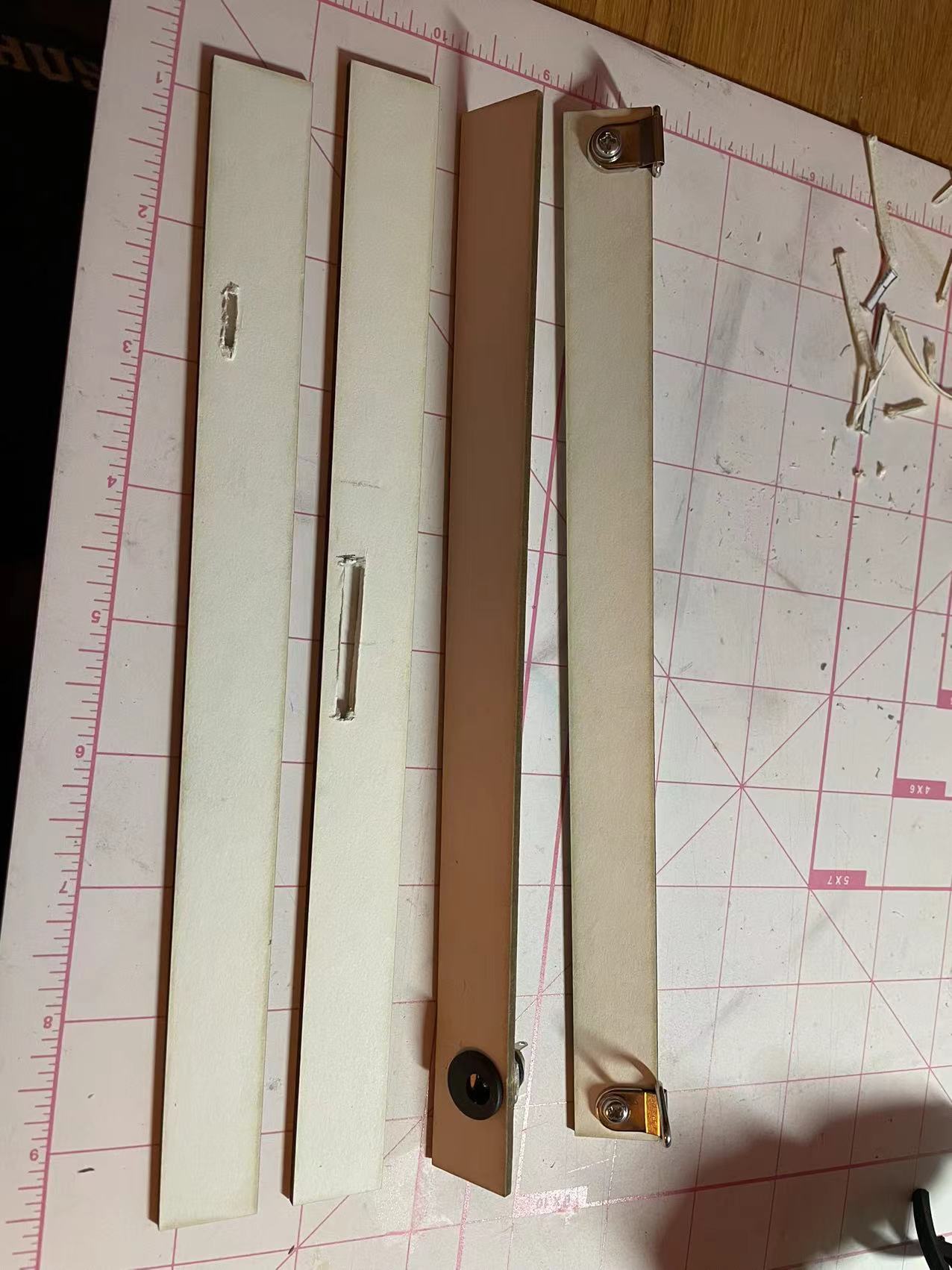
These strips are made to support the backside of the board because we don't want the wires to be exposed everywhere. I also cut out slits on two of them for the usb and switch input. It is quite fun working on the wiring process.
This is the wiring of the board. You can see that the usb head and the switches are stick out so that user can reupload images in the future.
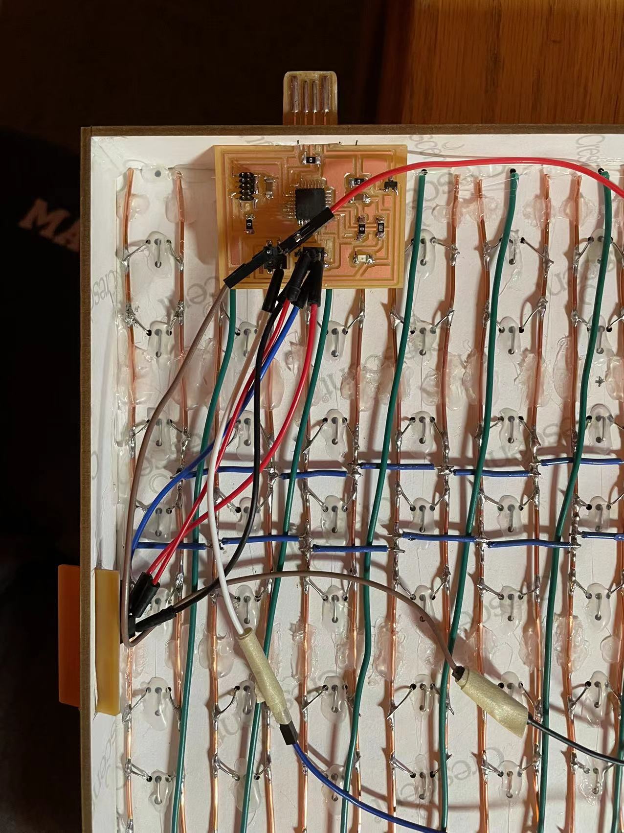
Here are some zoomed up images on the wiring. I also added the socket and connected it to the power and ground of the board.
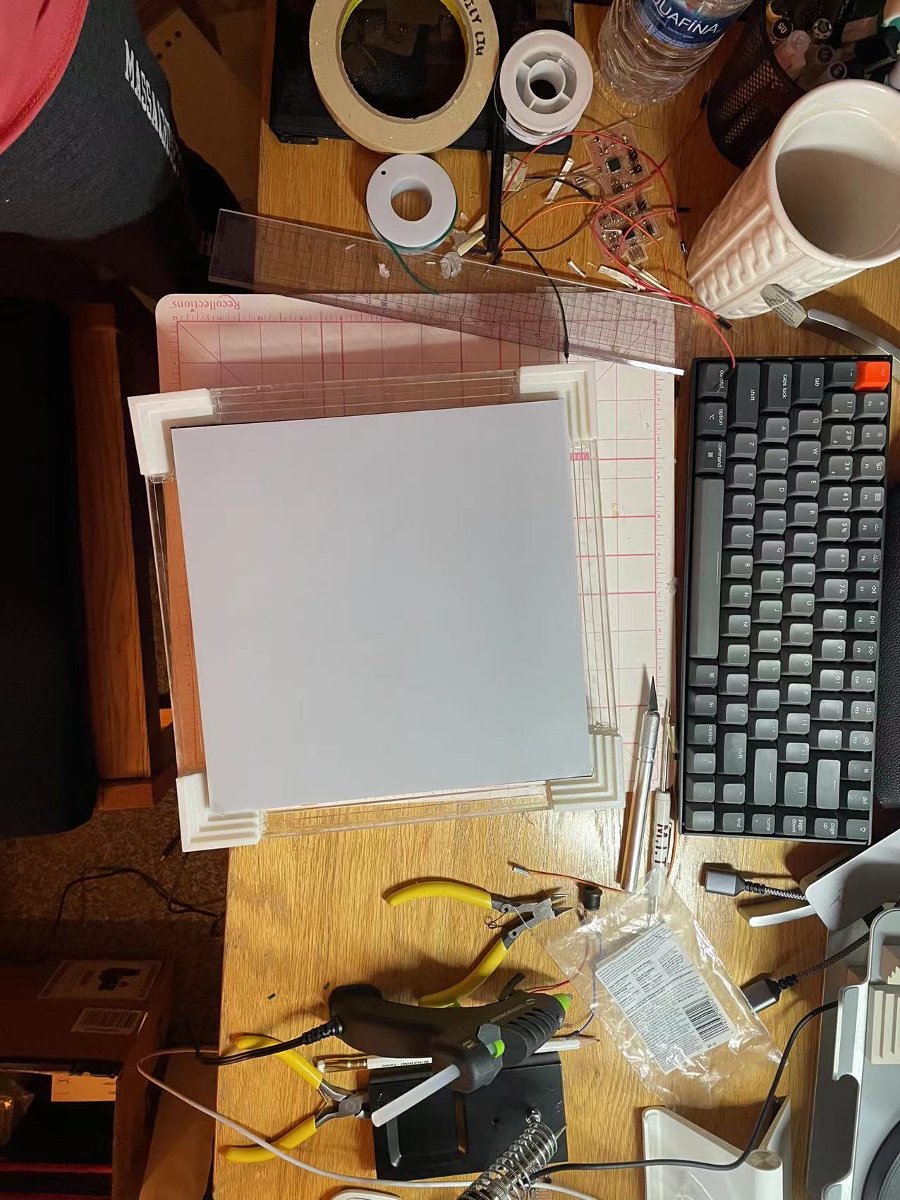
I added a thin sheet of acrylic to the back to prevent dust and also protect the wiring.
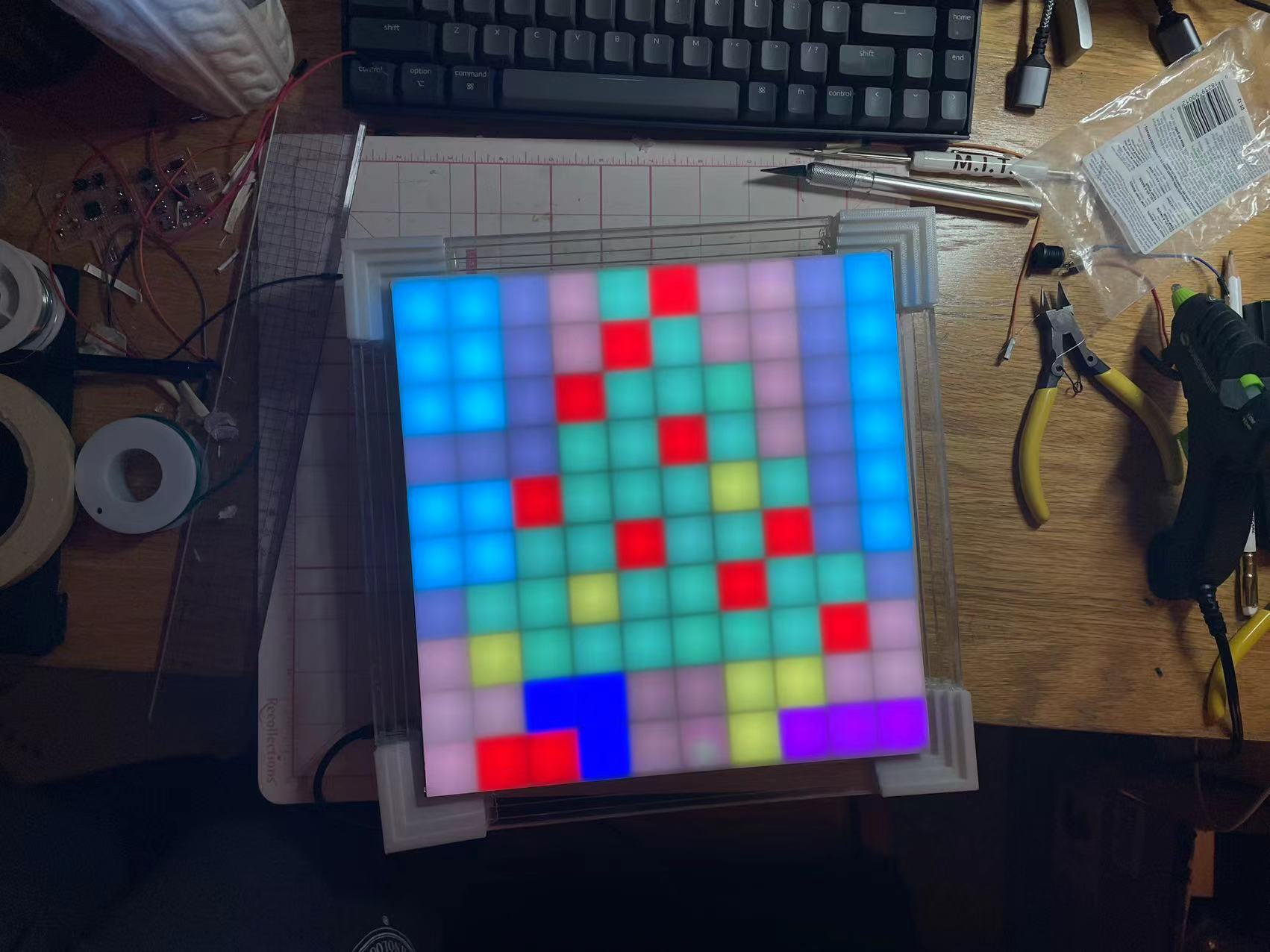
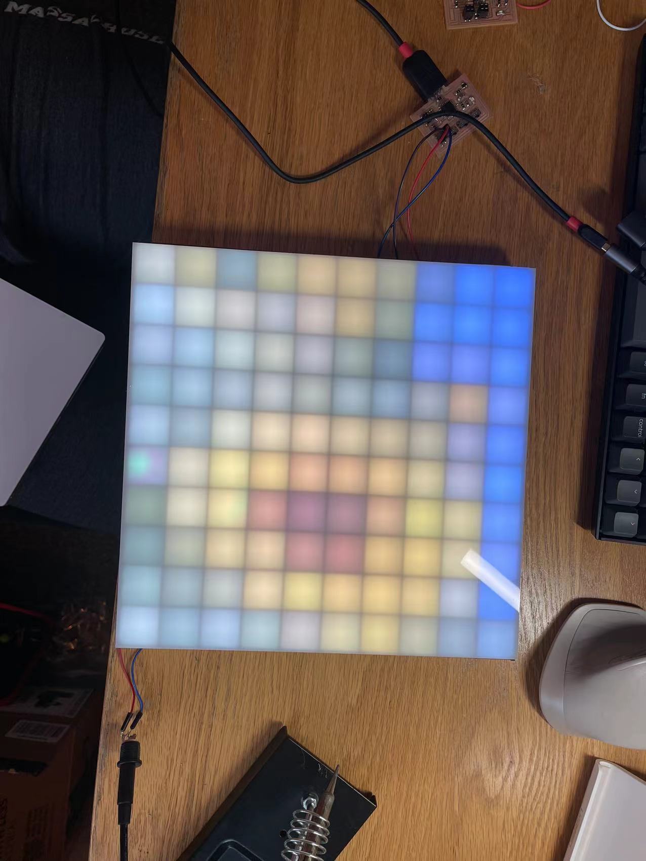
Here are the three images being displayed on my canvas! The switches work perfectly fine. I am really glad with how this turned out. I also added the acrylic frame to the model, making it more presentable and canvas like.
My table is a mess right now but I feel really accomplished having this project completed. The next step is to take good quality images and videos to document the process. I will also find a time to cnc cut the verticle rack next week.
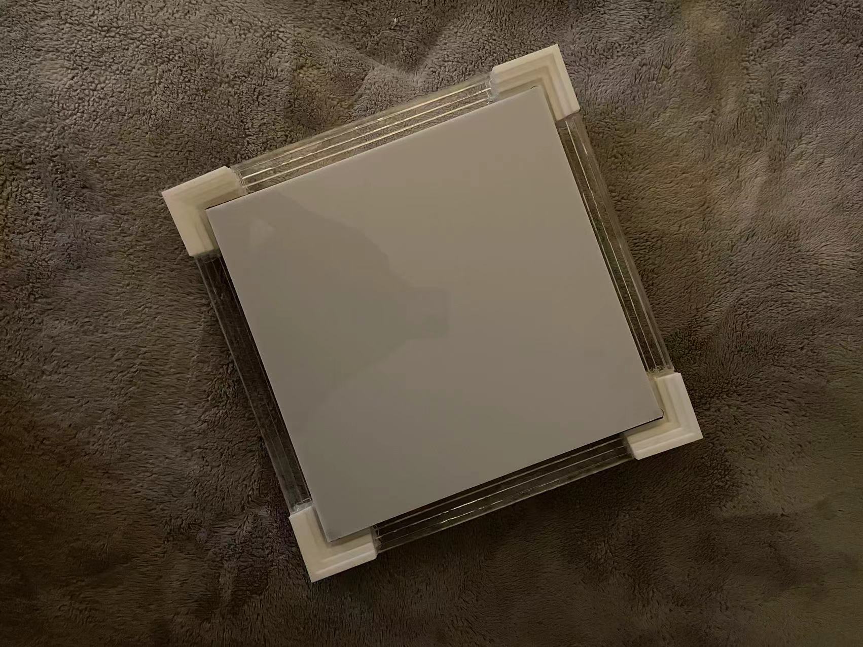
Here is how it looks with a cleaner background! It look pretty much like the model I made in rhino!
05 Final Conclusion and Thoughts
//
What does it do?
The pixel canvas can store up to three images and display whichever by user’s choice. There are three slide switches in the bottom of the frame used for changing the display images. User can also use my processing and Arduino code to analyze pixel information and re-upload display image.
Who's done what beforehand?
A YouTuber named GreatScott! has made similar LED matrix. A lot of reference and inspirations on how I constructed my matrix is from his video.
What did you design?
I designed the image storage function and also wrote some image processing code and interface for user to play around with.
What parts and systems were made?
The entire structure, frame, wiring, and electronic parts were made from scratch. The only parts that was bought are the WS2812 LEDs.
What processes were used?
All of the weekly assignment skills are incorporated into the design of the pixel canvas. 2D and 3D design was used in modeling the frame as will as drawing out templates for laser cutting. Additive and subtractive fabrication process was used in producing the structure of the frame (corners are 3D printed and laser cutter). The project used D21E microcontroller and Arduino programming language. The interfacing was done in processing. Lastly, the system integration and packaging are demonstrated through the wiring and exterior look. To be more specific, processes include the following: 3D printing, laser cutting, rhino modeling, fusion electronics design, Roland PCB milling, wiring, system integration, processing, Arduino.
What questions were answered?
Many questions were answered through out the process. Along the construction process, I figured out the image processing method, ways to store images on the microcontroller, and get the pixels to light up correctly in their position. BIG THANKS to all the TAs, instructors, classmates, and online resources that helped me figuring out these questions.
What worked? What didn't?
The wiring and Arduino code did work and the LEDs do light up correctly. However, I wasn’t able to figure out live display through the connection between Arduino and processing. This might be something I should improve on in the future.
How was it evaluated?
According to my initial proposal, this project should be evaluated based on whether it can display pixel images and whether the user can change and upload whatever image they wish to the frame. Overall, I would say it passed my standard of evaluation, however, there are much more to improve to hit the highest level of evaluation. For example, the process of uploading images are still very raw and repetitive.
What are the implications?
The frame is designed to hang up or placed anywhere as a decoration. Students can hang this in their dorm rooms as a piece of cool art work that emits colors into the room.
06 Material List
//
Material used for constructing the hardware
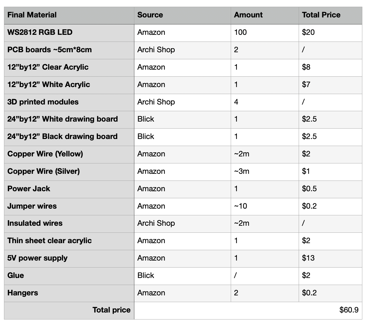
Here is the material list for my final project. I spent around $60 extra from what was offered in the shop. The most expansive part of the project is the WS2812 leds.
07 Reference
//
If the links doesn't work please view page source and open from there!
Make your own 10x10 LED Matrix