Week 4
Electronics Design
This week task was to design Echo Hello board, where we modified existing design to adding our LED and a button to it. I used KiCad to design my board, and used the ATtiny 412 microcontroller.
here's the referance file for ATtiny412 hello.t412.blink
Designing a PCB
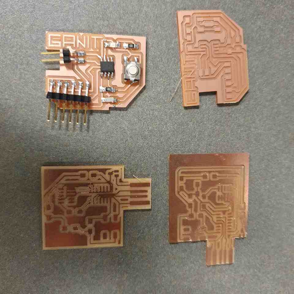
I designed and milled two boards because i couldnt make the test for the ATtiny 412, and it seems to be easier to design the hello.D11C.echo to test the button and the LED. At the end, Anthony helped me to test the ATtiny board - and it seems to work as expected. These are the few milled versions of the week's assignment.
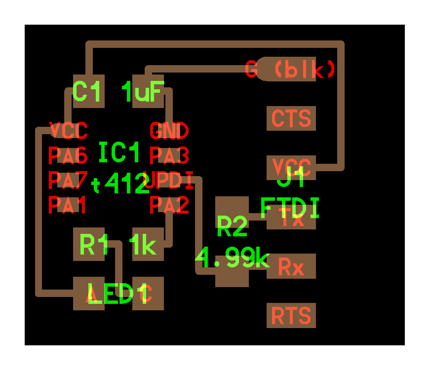
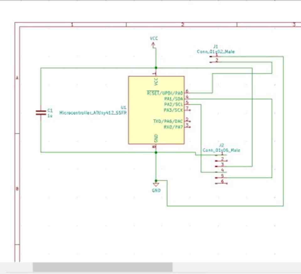
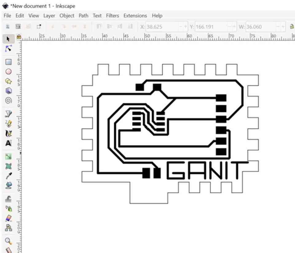
For the ATtiny412, I started with a simple version without adding button or LED. I worked on the design in KiCAD and exported the design to SVG file.
these are the components I used:
1. Microcontroller ATtiny 412
2. Connector male 01x06
3. Connector male 01x02
4. 1Pf capacitor
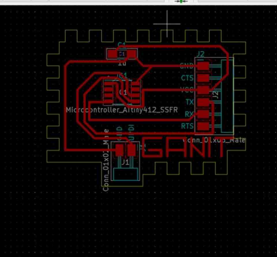
I chose and connected in the schematics in Kicad and matched them to the footprint editor from the Fab libaray.


The outline idea was to make a puzzle between a few pieces of milled PCB:
Here the 3D model of the first test in Kicad rendering: