Week 6
Embbeded Programming
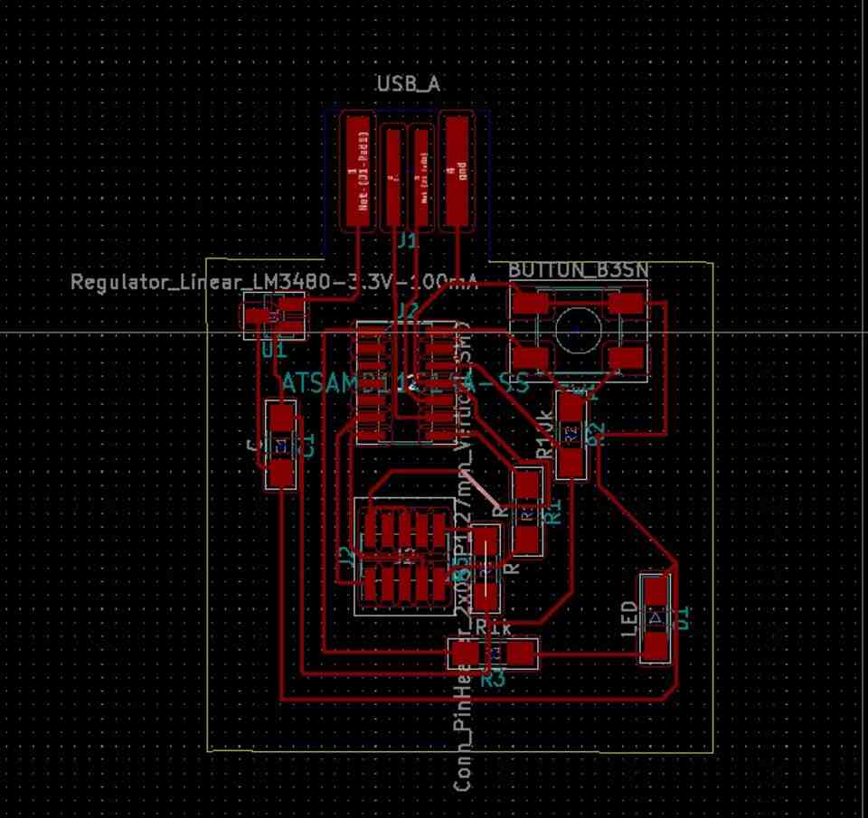
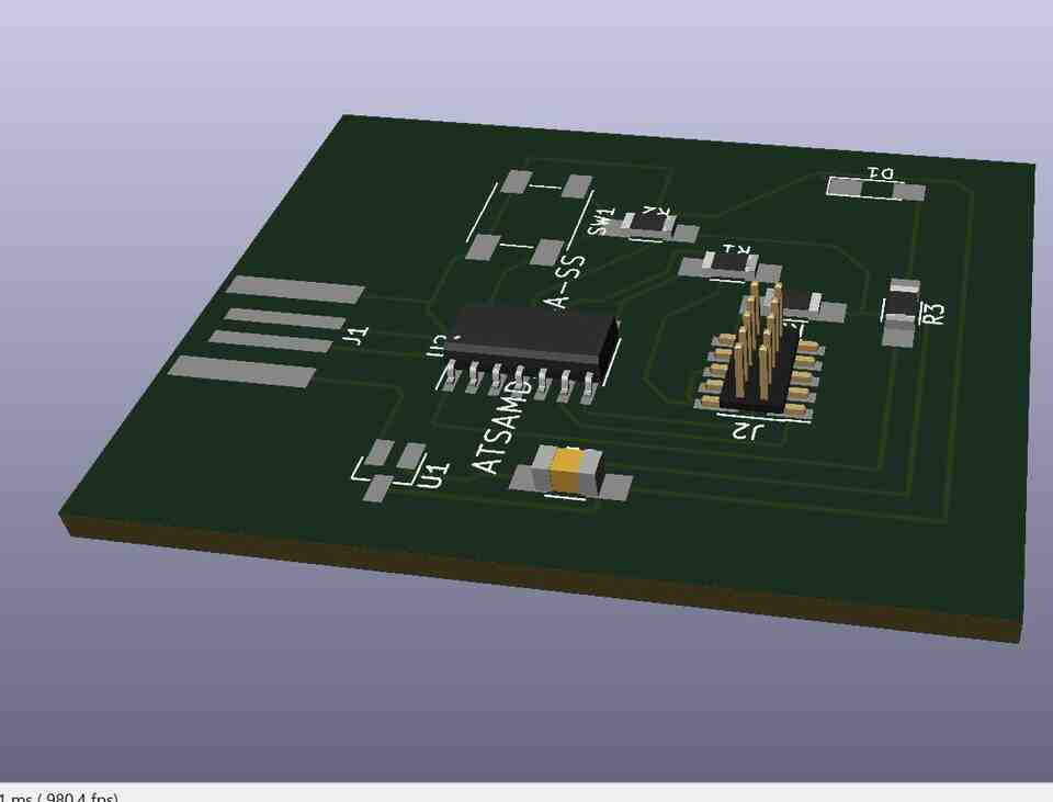
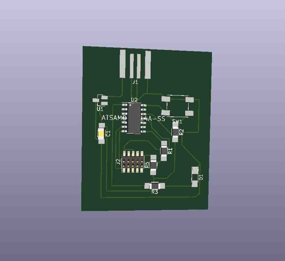
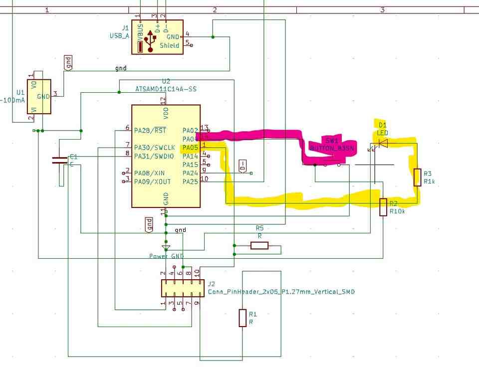
This week we learned how to program our board to do something. In week 4, I managed to have the process work with the Attiny412, but it was pretty hard to work with the connection with the code. I realized that for the next steps it will be more beneficial for me to work on the D11C board. So I made a new board, which has the USB embed in the board design. I had the schematics design partly working from the previous week, and Anthony helped me to debug the schematic design (one of the main problems was to design different pathways in one part because they ended up to be really too thin – so they got connected in the milling parts).
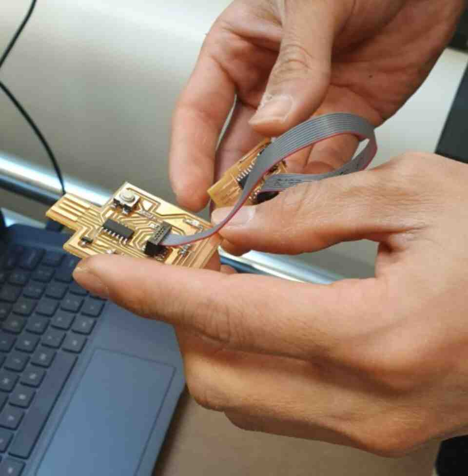
I added the button and the LED, and redesign, milled, solder and fabricate the board to an additional family member of my PCBs ( I think I have already 6 family members!)
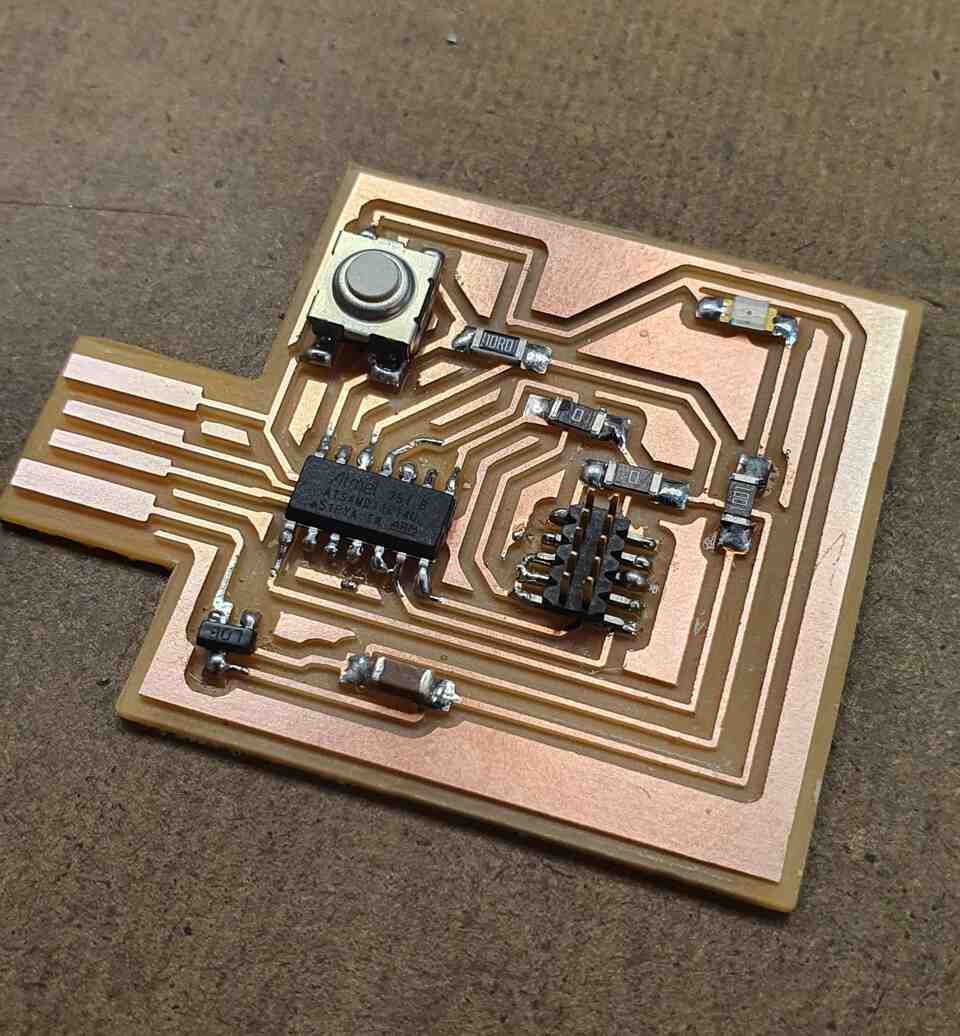
After making all the steps, we needed to bootload my D11C which Kim from the architecture department helped me. (thanks kim!) We discovered that I chose the wrong regulator, so I needed to replace and solder it again with the right one. It took some time – but at the end we could see that the LED is working which was a magical moment.