Week 2: Electronic Cutting
Instrument used: Roland MDX, Solder Stations
PCB: Printed circuit board
Milling: process of machining using rotary cutters to remove material by advancing a cutter into a workplace
End-mill: type of milling cutter. Differs from a drill because a drill is performed to originate a hole, but an end mill does other actions.
board made: Neil's hello.D11C.serial.5V.1.1 board [insert link here http://academy.cba.mit.edu/classes/embedded_programming/D11C/hello.D11C.serial.5V.1.1.jpg]
This was the week that I was probably most familiar with the language; however, even then, I've never had to solder anything as small as the 0ohm resistors used on the D11C serial 5V.1 board. I also learned that a lot of the haphazard way I had learned to solder/work with electronics was.... well, let's just say it's a shock I haven't burned more things.
On the bright side, i really enjoyed the PCB milling. I have only ever worked with breadboards and pre-made PCBs, so getting to learn how to make my own has been really rewarding. i'm not entirely sure that i would be able to easily make a larger pcb for my research without much trial and error, so i intended to make a few simpler designs. However, Jen mentioned that some of the materials are in low stock, so i hesitated making a second pcb with a design. Maybe in the future?
The Milling
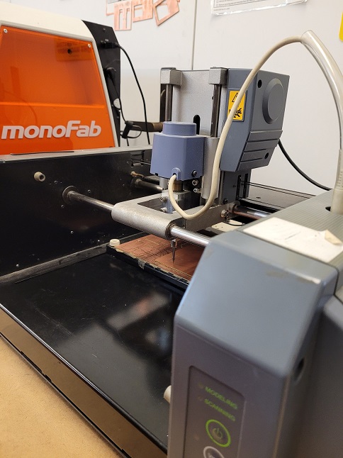
Jen had informally run me through the older MDX-20 when I was working on some laser cuts, so that is what I worked on. Personally, I liked that the z-axis was set "manually" on the instrument itself and not by program-- I personally like feeling and seeing a more direct effect of whatever button I'm pushing. I did have to wear safety glasses during. Additionally, I found troubleshooting easier since the older instrument doesn't have a cover on it so I could see more closely what was happening.
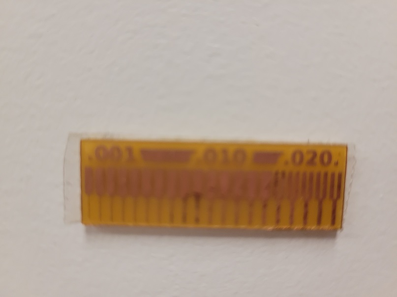
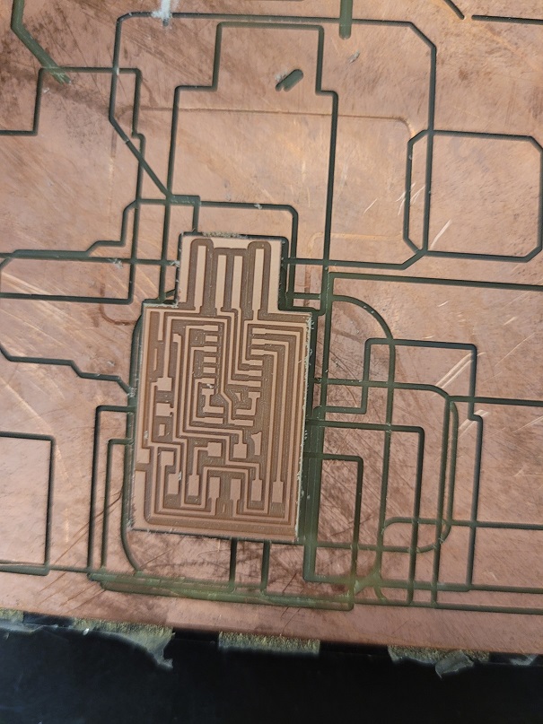
Here you can see the milled group assignment. It was an exercise in testing just how fine a line the instrument could cut, which is useful information if I need to cut very small pcb connections.
After vacuuming down the baseboard, and taping down our piece with double sided tape--THOROUGHLY-- we ran the MODS program with the chosen board. The MDX-20 requires wearing safety goggles. Pictured above is the first trace.
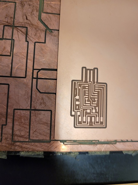
While our first attempt was successful, the second attempt at the PCB was a bit of a bust. As seen here, only about half of the board was cut all the way through. The 1/32" end mill was likely pressed too far into the board and it snapped partway through, making an alarming CRACK noise. Lesson learned: just "dropping" the end mill enough to tap the board is all you need to do!
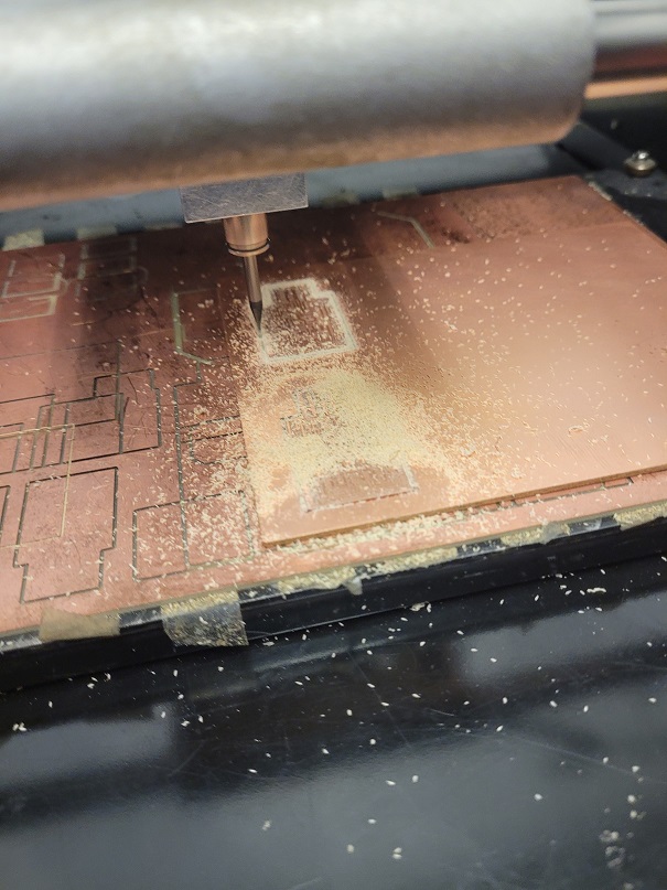
Here, Rihn and I are milling a second PCB. Luckily, since we hadn't moved the first one, it was easy to figure out the origin and keep finishing the cut so at least nothing was wasted! You can see us cutting it over in this picture.
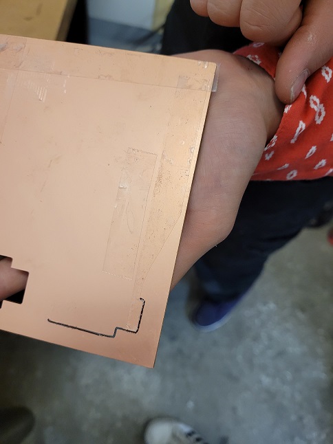
Here is the first board, still stuck to the baseboard after we peeled off the surrounding copper plating. Huzzah!
The Soldering
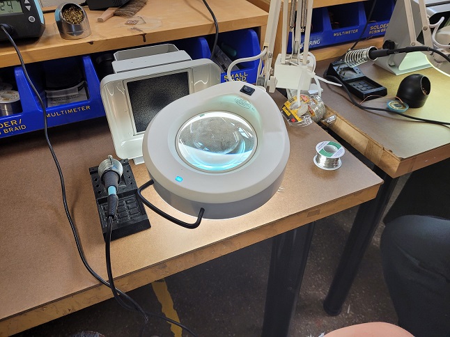
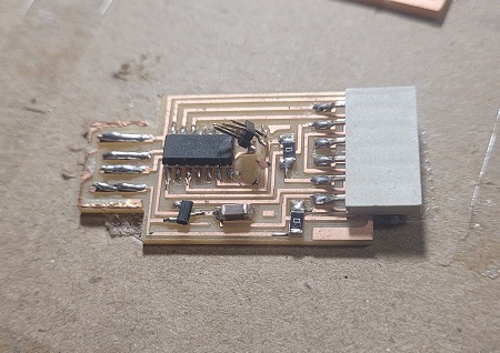
Here is my solder station set-up. I've never used such tiny components before so the magnifying glass was certainly necessary before. The vent was also a nice touch.I practiced on some leftover cut boards, before I started on my real piece. I also washed my board with gojo pumice. Running my PCB under water was... certaintly a weird feeling.
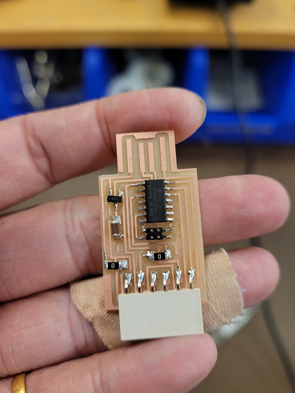
After a lot of close work, here is the final piece! Obviously not the prettiest, with some lopsided pieces, but this definitely took awhile.
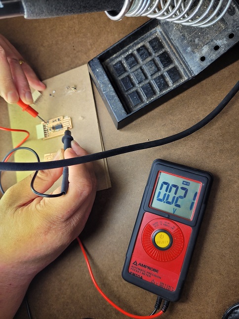
Testing my PCB with a multimeter voltage function involved touching the black end to the ground (GND) on the "USB" part, then testing all the ground portions of the rest of the board. If the voltage detects a complete path (a convenient beep!) between these means that it was soldered correctly.
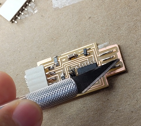
The final bit was extra: removing this outer layer in an attempt to prevent the USB reader from "getting confused" by these extra metal pieces. This was the most indelicate part of the week, actually. This week, our TAs told us that checking with the multimeter was sufficient enough for "testing" if it worked. This board was to be used later in embedded programming week, but my board met an unfortunate ending between the end of this week and then.