Group Assignment: Measure Power Consumption of Output Device
Our group project is to measure the power consumption of an output device. P = I * V, so I need to measure voltage and current. I used a multimeter to this.
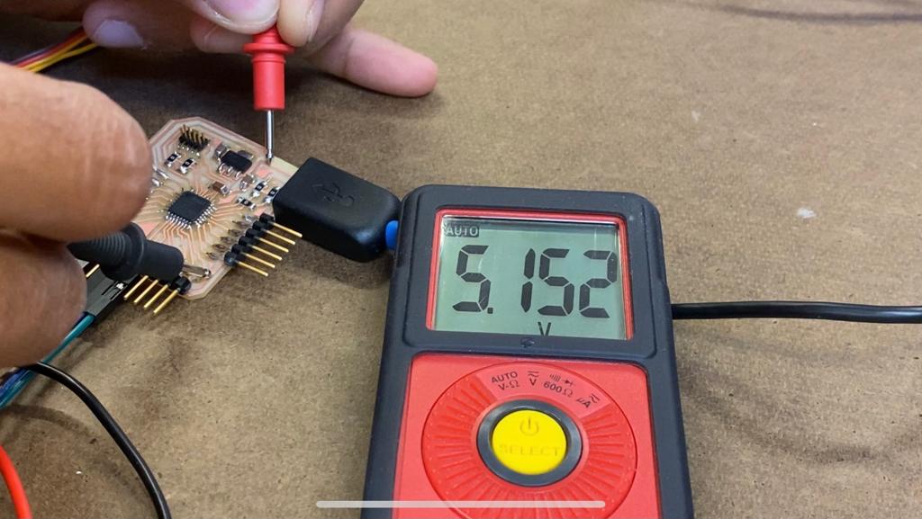
To measure voltage, I set the multimeter to the voltage setting, and placed the red tip on my VCC (5V) trace, and placed the black tip on my GND trace on my dev board. I measured 5.152V.
To measure current, I set the multimeter to the current setting. In order to measure current, the multimenter needs to be in-series in your circuit so that current can flow through it. Because a servo motor doesn't continuously draw current, I got variable readings, as you can see in the video. It seems that at its peak it was drawing 0.28 Amps.
P = I * V = 0.28 Amps * 5.152V = 1.442 Watts
Individual Assignment: Add an Output Device to a Microcontroller Board
Servo Motors
For this week we had to add an output device to a microcontroller board that we designed and program it to do something. For my final project I will need to control multiple servo motors, so I decided to add those to my dev board from last week.
First I needed to decide which servo motor to use, since they vary quite a lot in terms of voltage and stall torque. Based on the existing page turning machine I discovered, they use the HS-322HD servo. The closest servo in our inventory that I found is the HK15138 servo. Here are the specific stats:
| HS-322HD | HK15138 | |
| Voltage Range | 4.8V - 6.0V | 4.8V - 6.0V |
| Stall Torque (4.8V) | 3.0 kg | 3.8 kg |
| Stall Torque (6V) | 3.7 kg | 4.3 kg |
| Weight | 43g | 38g |
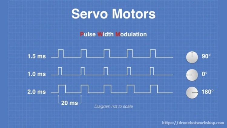
Servo's work by Pulse Width Modulation (PWM). Essentially, by varying the amount of time a high signal is sent, you can command the servo to rotate different degrees. Here is a helpful diagram:
Connecting the Servo's
Connecting the servo motors is actually very straightforward. A servo has 3 cables: Voltage (4.8-6V in my case), GND, and Signal. To start, I hooked up 2 servos to my dev board - for the signal lines I connected them to analog pins PA06 and PA07. I also connected my button breakout board from last week to toggle the two motors.

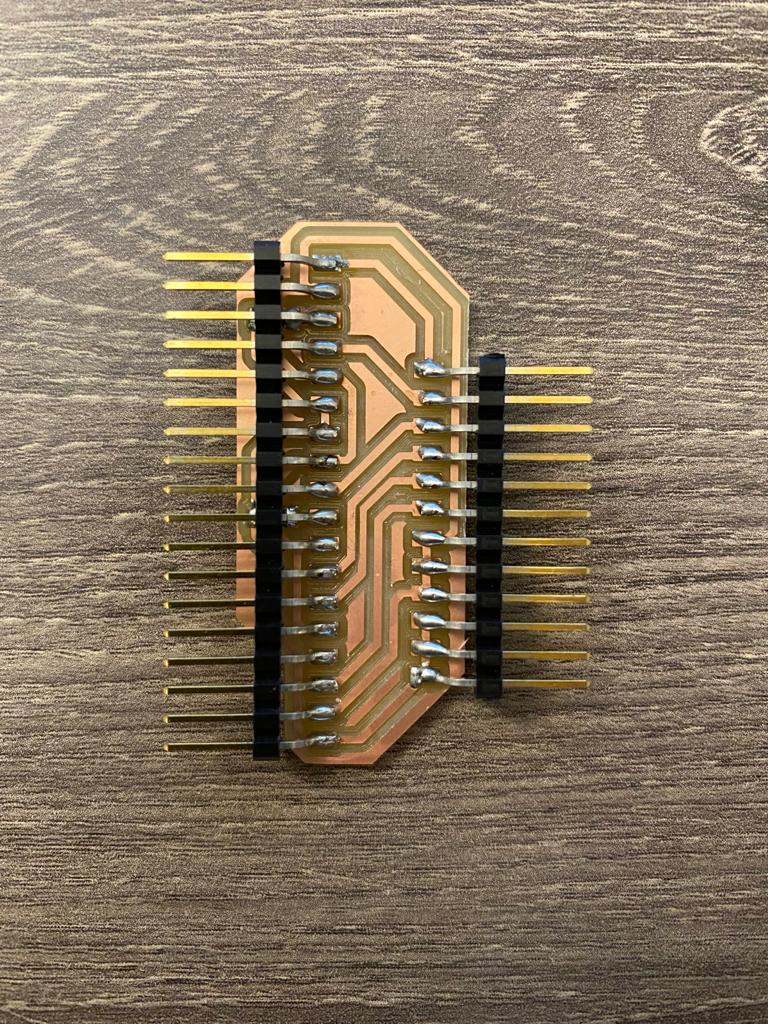
This worked well! However, I noticed that managing the cables may start to get annoying, especially since I need to be splitting the the V, GND, and Signal lines on the servo. I thought it would be useful to design a "servo hub" breakout board where I can more easily organize my servos and from that board directly connect the servo lines. I can also have direct power and gnd lines which I can attach to an external power source. This way, the only connects to my central dev board would be a single 5V and GND cable, and cable for each signal of a servo. For this, I just used the same FTDI headers. Here is the board:
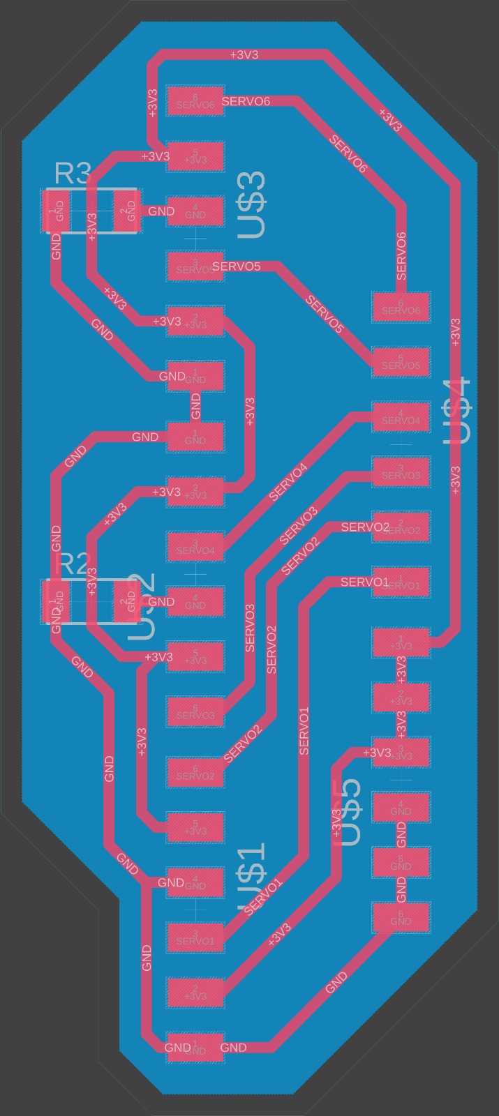
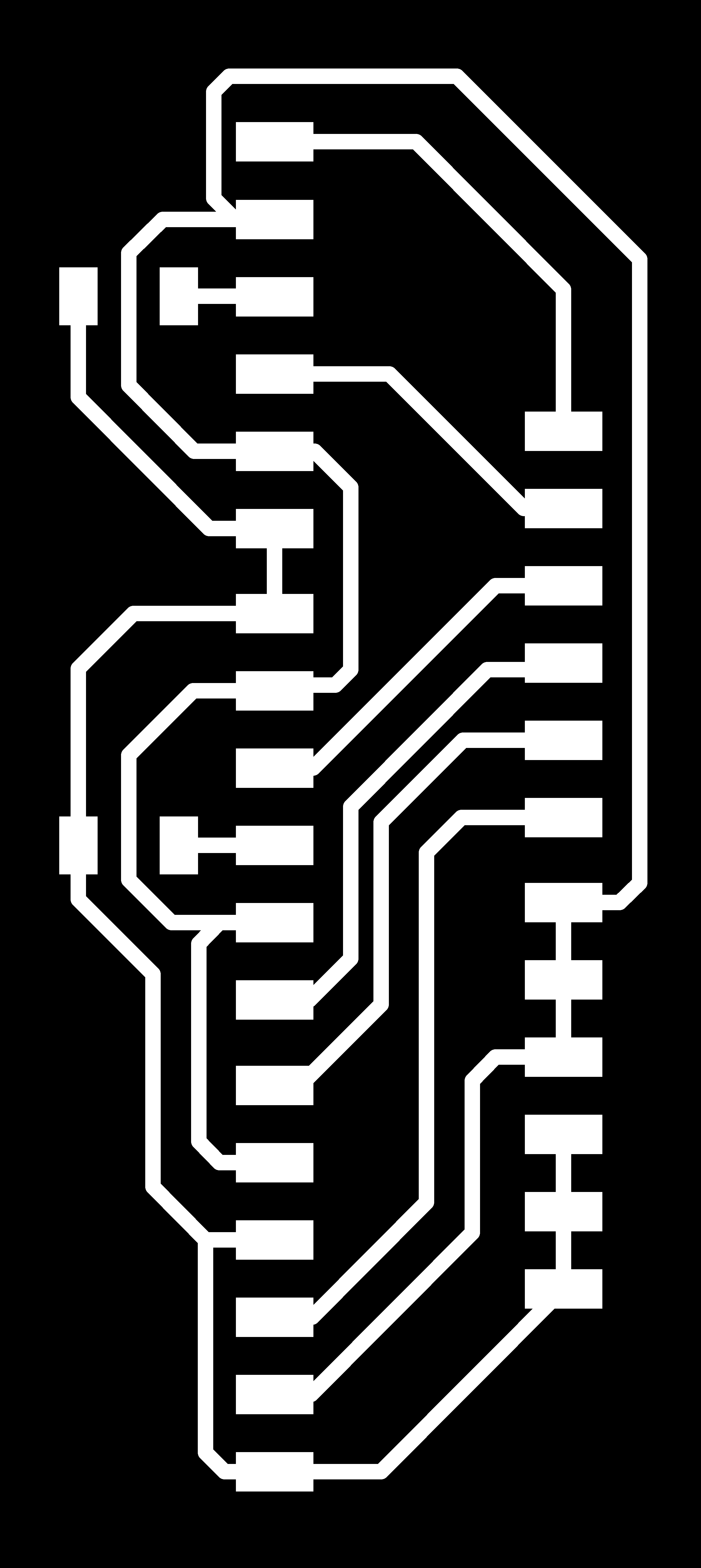

And here is the servo hub board:

You can see how to hub looks once servos are connected. The servo connections are on the left side, and the corresponding signal wires (yellow) come out the right side and they connect to the dev board. You also see the 5V (red) and GND (dark purple) cables on the right. This will make connecting servos much easier and cleaner.
Lastly, I wanted to test my new hub board with 3 servos, and it worked! Note that here I am powering all 3 via USB. I would definitely want to use an external power source for a more reliable and robust source of voltage.
Files
Servo Hub Board Traces (remember to set DPI 3000 in mods!)Servo Hub Board Outline (remember to set DPI 3000 in mods!)
Servo Control Code