ESP's and tiny traces are the bane of my existance
Closer Inspection
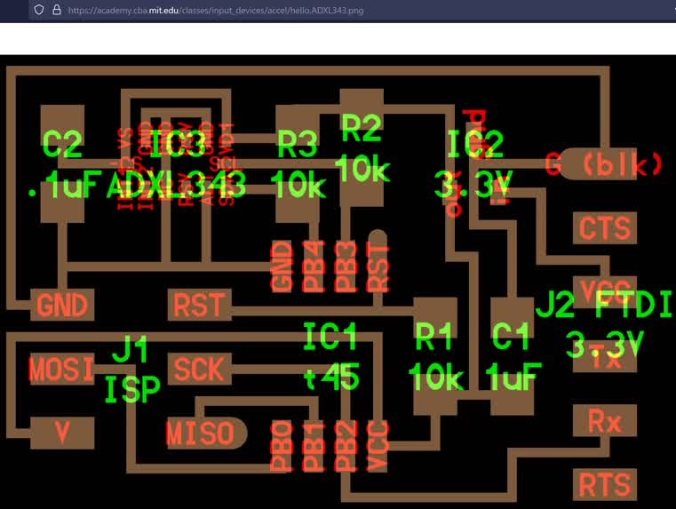
I was experienceing issues with how tiny the ADXL343
accelerometer was, and how the initial tracing
and seperation setting in kicad made it difficult
to route tracks. I did notice that Neil was
able to make a track run through the little SMD
package, and that the pads were as large as the
traces. I managed to mpdfy the settings in kicad
to allow for closer together traces and was
able to keep using the 1/64" end mill rather
than having to swap to an even smaller one.
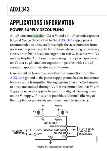
I also noticed extra components (capacitors and
resistors) on the example accelerometer board,
which caught my interest. I was able to ctrl-F
"capacitor" on the ADXL343 datasheet to find
out why, and added them to my board as well.
Thank Neil!
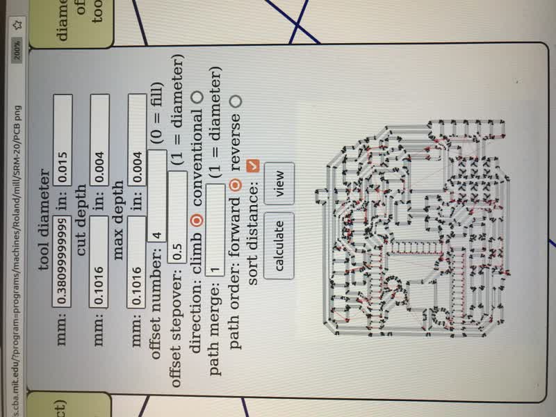
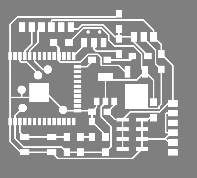
Milling went a lot smoother than before.
The mods trick of pretending the end mill is
.015 instead of .0156 helps a lot in ensuring
everything is seperated. Otherwise I would have
to come in with an exacto afterwards.
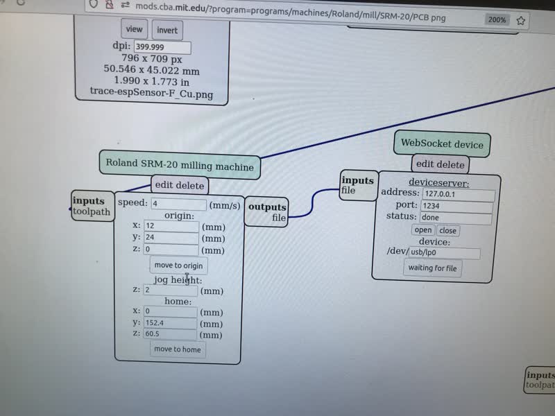
Another tip us to always take a picture
of your origin point in case you have to reset the machine.
remembering my origin!
preview with the trick-mods-with-a-smaller-endmill tactic
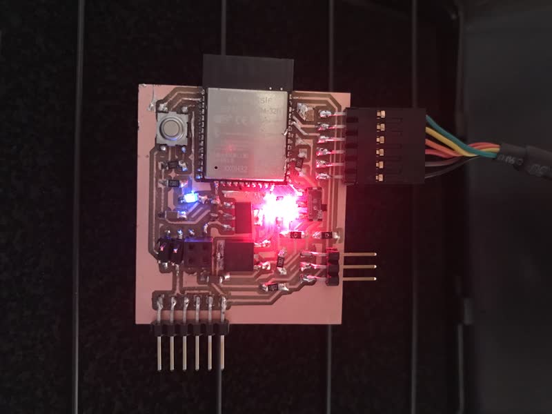
Stuffing and Soldering
Was a mess. I think I shorted some of the
ESP32 pins, and it would not accept code.
Since I messed up my first board and was
away from lab, I decided
to scavange components to populate a new
milled board (which I did have on hand).
I added an on-board LED for blink tests. Deciding
the polarity of an LED was a bit tricky, but this
site helped:
SMD LED polarity (https://lighthouseleds.com/blog/polarity-guide-of-0402-0603-0805-1206-and-most-all-smd-leds.html)
Alternatively, other say I could've used a multimeter
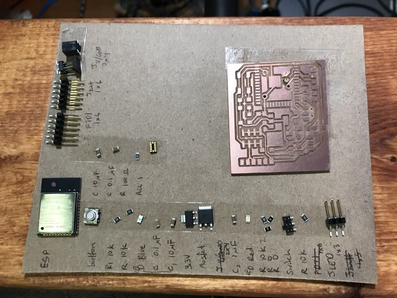
tiny components.
I had two boards and did indeed need to steal from one to populate the other.
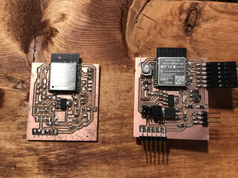
Beautifully janky
It's a mess of a board, but it actually
programs!
I gave it a neopixel example, and it lit up
an adressable (meaning each "pixel" can be
controlled individually) LED strip!
Another useful tool Anhad introduced me to: https://falstad.com/circuit/
- A circuit simulator, to help understand and visualize
what is going on.
I used it to look at things in my design, most
notably the logic level converter, which I was so sure
should have worked.
UPDATE: Turns out even though the
theory and circuit does work, sourcing components
was part of the issue since the mosfet I was using may not
be fast enough to relay signals to the adressable LEDs.